EP1472005B1 - Tropfbewässerungsschlauch mit druckausgleich - Google Patents
Tropfbewässerungsschlauch mit druckausgleich Download PDFInfo
- Publication number
- EP1472005B1 EP1472005B1 EP03737724.9A EP03737724A EP1472005B1 EP 1472005 B1 EP1472005 B1 EP 1472005B1 EP 03737724 A EP03737724 A EP 03737724A EP 1472005 B1 EP1472005 B1 EP 1472005B1
- Authority
- EP
- European Patent Office
- Prior art keywords
- hose
- emitter
- section
- bottom wall
- inlet
- Prior art date
- Legal status (The legal status is an assumption and is not a legal conclusion. Google has not performed a legal analysis and makes no representation as to the accuracy of the status listed.)
- Expired - Lifetime
Links
- 230000002262 irrigation Effects 0.000 title claims description 17
- 238000003973 irrigation Methods 0.000 title claims description 17
- XLYOFNOQVPJJNP-UHFFFAOYSA-N water Substances O XLYOFNOQVPJJNP-UHFFFAOYSA-N 0.000 claims description 63
- 239000000463 material Substances 0.000 claims description 19
- 229920006342 thermoplastic vulcanizate Polymers 0.000 claims description 4
- 230000003247 decreasing effect Effects 0.000 claims description 3
- 230000002829 reductive effect Effects 0.000 claims description 3
- 230000002787 reinforcement Effects 0.000 claims description 3
- 238000004891 communication Methods 0.000 claims description 2
- 239000012530 fluid Substances 0.000 claims description 2
- 238000004519 manufacturing process Methods 0.000 description 5
- 230000006835 compression Effects 0.000 description 4
- 238000007906 compression Methods 0.000 description 4
- 239000013536 elastomeric material Substances 0.000 description 4
- 239000002245 particle Substances 0.000 description 4
- 230000004044 response Effects 0.000 description 3
- 239000004698 Polyethylene Substances 0.000 description 2
- 230000007423 decrease Effects 0.000 description 2
- 229920001971 elastomer Polymers 0.000 description 2
- 238000001125 extrusion Methods 0.000 description 2
- -1 polyethylene Polymers 0.000 description 2
- 229920000573 polyethylene Polymers 0.000 description 2
- 230000001105 regulatory effect Effects 0.000 description 2
- 230000003014 reinforcing effect Effects 0.000 description 2
- 230000004043 responsiveness Effects 0.000 description 2
- 230000002441 reversible effect Effects 0.000 description 2
- 229920002725 thermoplastic elastomer Polymers 0.000 description 2
- 241001553014 Myrsine salicina Species 0.000 description 1
- 230000002411 adverse Effects 0.000 description 1
- 230000015572 biosynthetic process Effects 0.000 description 1
- 238000010276 construction Methods 0.000 description 1
- 230000000694 effects Effects 0.000 description 1
- 239000000806 elastomer Substances 0.000 description 1
- 239000003337 fertilizer Substances 0.000 description 1
- 239000003673 groundwater Substances 0.000 description 1
- 239000004615 ingredient Substances 0.000 description 1
- 229940023495 irrigation product Drugs 0.000 description 1
- 239000011159 matrix material Substances 0.000 description 1
- 238000000034 method Methods 0.000 description 1
- 239000000203 mixture Substances 0.000 description 1
- 230000036961 partial effect Effects 0.000 description 1
- 238000004513 sizing Methods 0.000 description 1
- 239000007779 soft material Substances 0.000 description 1
- 239000002689 soil Substances 0.000 description 1
- 239000007787 solid Substances 0.000 description 1
- 239000007921 spray Substances 0.000 description 1
- 239000002352 surface water Substances 0.000 description 1
- 239000012815 thermoplastic material Substances 0.000 description 1
- 230000000007 visual effect Effects 0.000 description 1
Images



Classifications
-
- A—HUMAN NECESSITIES
- A01—AGRICULTURE; FORESTRY; ANIMAL HUSBANDRY; HUNTING; TRAPPING; FISHING
- A01G—HORTICULTURE; CULTIVATION OF VEGETABLES, FLOWERS, RICE, FRUIT, VINES, HOPS OR SEAWEED; FORESTRY; WATERING
- A01G25/00—Watering gardens, fields, sports grounds or the like
- A01G25/02—Watering arrangements located above the soil which make use of perforated pipe-lines or pipe-lines with dispensing fittings, e.g. for drip irrigation
- A01G25/023—Dispensing fittings for drip irrigation, e.g. drippers
-
- Y—GENERAL TAGGING OF NEW TECHNOLOGICAL DEVELOPMENTS; GENERAL TAGGING OF CROSS-SECTIONAL TECHNOLOGIES SPANNING OVER SEVERAL SECTIONS OF THE IPC; TECHNICAL SUBJECTS COVERED BY FORMER USPC CROSS-REFERENCE ART COLLECTIONS [XRACs] AND DIGESTS
- Y02—TECHNOLOGIES OR APPLICATIONS FOR MITIGATION OR ADAPTATION AGAINST CLIMATE CHANGE
- Y02A—TECHNOLOGIES FOR ADAPTATION TO CLIMATE CHANGE
- Y02A40/00—Adaptation technologies in agriculture, forestry, livestock or agroalimentary production
- Y02A40/10—Adaptation technologies in agriculture, forestry, livestock or agroalimentary production in agriculture
- Y02A40/22—Improving land use; Improving water use or availability; Controlling erosion
-
- Y—GENERAL TAGGING OF NEW TECHNOLOGICAL DEVELOPMENTS; GENERAL TAGGING OF CROSS-SECTIONAL TECHNOLOGIES SPANNING OVER SEVERAL SECTIONS OF THE IPC; TECHNICAL SUBJECTS COVERED BY FORMER USPC CROSS-REFERENCE ART COLLECTIONS [XRACs] AND DIGESTS
- Y02—TECHNOLOGIES OR APPLICATIONS FOR MITIGATION OR ADAPTATION AGAINST CLIMATE CHANGE
- Y02P—CLIMATE CHANGE MITIGATION TECHNOLOGIES IN THE PRODUCTION OR PROCESSING OF GOODS
- Y02P60/00—Technologies relating to agriculture, livestock or agroalimentary industries
- Y02P60/20—Reduction of greenhouse gas [GHG] emissions in agriculture, e.g. CO2
- Y02P60/21—Dinitrogen oxide [N2O], e.g. using aquaponics, hydroponics or efficiency measures
Definitions
- This invention relates generally to a pressure compensating irrigation hose, and more particularly to a pressure compensating hose having an elongate elastomeric member, which, with the hose, forms an irrigation hose having a plurality of pressure compensated emitters.
- Agricultural irrigation systems in use today are predominantly flood and sprinkler systems. These systems have numerous shortcomings, including inefficient use of water and fertilizers, high labor and energy costs, pollution of surface and ground waters, and poor uniformity of water application on steep or uneven terrain.
- Drip irrigation systems are being developed and adopted to address the above-noted problems.
- a hose having a continuous emitter such as the Aqua-TraXX® hose of The Toro Company.
- hose includes the use of a continuous non-elastic strip which, in conjunction with the hose, forms a plurality of emitters. Perforations are then formed in the outside surface of the hose into the outlet of the emitter.
- such hose is not pressure compensating, and is therefore not suitable for use on steep or non-uniform terrain.
- U.S. Patents 4,984,739 and 5,333,793 are examples of a hose having a continuous emitter and also include a pressure compensating system.
- the present invention provides for a pressure compensating drip emitter irrigation hose which utilizes a continuous elastomeric strip member having a hardness which is less than that of the hose.
- US-A-5829686 discloses a drip irrigation emitter defining a flow control passageway having an inlet to communicate with a supply of pressurized water, and an outlet to communicate with a water discharge opening.
- the system includes an obstruction formation between the flow control passageway outlet and the water discharge opening to produce a relatively small obstruction to the flow in the direction from the flow control passageway outlet to the water discharge opening, and a relatively large obstruction to the flow in the reverse direction such as to reduce the possibility of the entry of external solid particles into the emitter via the water discharge opening.
- the invention provides a pressure compensating drip irrigation hose for distributing water comprising:
- the hose 20 includes a wall 21 that has an inner surface 21a.
- a continuous elastomeric strip member 30 is secured to the inner surface 21a.
- the continuous elastomeric strip member 30 is an extruded elongate member and is manufactured prior to the manufacturing of the hose 20.
- the hose 20 is then extruded, by means well known in the art, around the continuous elastomeric strip member 30 so as to secure the continuous elastomeric strip member 30 to the inner surface 21a of the wall 21.
- the wall 21 is extruded from any suitable material such as polyethylene.
- the hose 20 may have any suitable diameter such as from 10 millimeters to 35 millimeters.
- the continuous elastomeric strip member 30 is extruded from an elastomeric material such as thermoplastic elastomer.
- the continuous elastomeric strip member 30 is softer than the wall 21.
- the wall 21 may have a hardness of from 45 to 65 on the Shore D scale whereas the continuous elastomeric strip member 30 may have a hardness of from 40 to 70 on the Shore A scale.
- the continuous elastomeric strip member 30 is a continuous extrusion of a plurality of emitter segments which, in combination with the wall 21, form a plurality of emitter units.
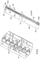
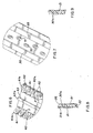
- One emitter segment of the continuous elastomeric strip member 30 is shown in Figures 4 and 10 .
- the continuous elastomeric strip member 30 includes an inlet section 40, a pressure reducing section 60, a pressure responsive section 70 and an outlet section 80.
- the inlet section 40 is one continuous segment, but as shown in the drawings, includes a first segment 40b and a second segment 40a. While Figure 4 represents one complete emitter segment, 40a is a portion of one emitter segment and 40b is a portion of a second emitter segment.
- the inlet section 40 has been broken into two components, it being understood that a full inlet section would include both section 40a and 40b.
- the continuous elastomeric strip member 30 has a bottom wall 31, a first side wall 32 and a second side wall 33.
- the side walls 32 and 33 are operatively connected to the bottom wall 31 and are preferably extruded with the bottom wall 31.
- the height of the walls 32 and 33 are preferably the same. Referring now to Figures 1 , 6 and 11 , it can be seen that the rails 32, 33 do not extend in the inlet section 40.
- a plurality of spaced oval shaped inlet members 41 are operatively connected to the bottom wall 31.
- the top surface 41a is at the same height as the top of the rails 32, 33.
- the irrigation hose 20 includes a plurality of emitter units 20a.
- the hose 20 is a continuous extrusion and therefore may be cut and packaged in any length.
- a reinforcement member 42 is positioned adjacent the outer portions of the oval 41.
- the main water passageway 20b provides a flow of water through the irrigation hose 20. Water will enter from the main water passageway 20b between the oval inlet members 41 and into the emitter and the emitter water passageway 30a.
- a second reinforcing member 43 extends through the inlet section 40.
- the reinforcing member 43 has its top surface 43a at the same height as the top of the side walls 32, 33 and is therefore welded/bonded to the inner surface 21a.
- the pressure reducing section 60 Downstream from the inlet section 40 is the pressure reducing section 60.
- a plurality of spaced preformed members 61 are operatively connected to the bottom wall 31 and side wall 32 and extend generally inward from the side wall 32.
- a plurality of spaced preformed members 62 are operatively connected to the bottom wall 31 and second side wall 33.
- the preformed members 61, 62 have an impact on the flow rate and the performance of the emitter 20a.
- the preformed members 61, 62 have sharp features so as to create the most turbulence in the flow of the water. This turbulence is required for the emitter to control the flow rate at lower pressures, before the pressure responsive section 70 begins to take control.
- the preformed shapes cause the flow of water to be disrupted in such a way as to cause the water to reverse directions and cause turbulence. These turbulences cause the water to slow and loose energy in the form of pressure.
- the top surface 61a, 62a is at the same height as the top surface of the side walls 32, 33. Therefore, the top surface 61a, 62a is bonded to the inner surface 21a of the wall 21. It is important that there be very little variation from emitter to emitter so that the amount of water that exits each emitter is the same. By having the preformed shapes 61, 62 bond to the inner surface 21a, the amount of variation from emitter to emitter is reduced.
- the preformed members 61, 62 are generally elongate and have a length which is sufficient to extend more than one half of the distance between the side walls 32, 33. Therefore, there is not a straight passageway for the water to flow. Instead, it must take a tortuous path around the preformed members 61, 62 as the water goes downstream in the emitter. Further, the preformed members 61, 62 have sharp features so as to create the most turbulence in the flow of water. This turbulence is required for the emitter to control the flow rate at the lower pressures, before the pressure responsive section 70 begins to take control.
- the preformed members 61, 62 have a generally rectangular shape that extends into the emitter water passageway.
- steps 63-65 that are formed in the preformed 61 and three steps 66-68 that are formed in the preformed 62.
- the steps have a planar section that is generally perpendicular to the edge, thereby creating a plurality of sharp surfaces to cause water turbulence.
- the inlet members 41 act as a filter in that the distance between the inlet members 41 is less than any distances between other portions of the continuous elastomeric strip member 30 along the emitter passageway. Therefore, any particles that would pass through the inlets 41 should be able to pass through the emitter water passageway as the remaining openings are greater than the distance A.
- the pressure responsive section 70 Moving down from the pressure reducing section 60 is the pressure responsive section 70.
- the bottom wall 31 of the pressure responsive section 70 has a regulated thickness that is less than the bottom wall thickness in the rest of the emitter segment. This construction gives the pressure responsive section the ability to change shape in response to the pressure changes inside of the main water passageway 20b.
- the pressure responsive section 70 has two offset rows of preformed shapes. The first row has a plurality of preformed shapes 71. A second row of preformed shapes 72 are in axial alignment with each other. The preformed shapes 71, 72 are offset by a distance C which is approximately 0.125 mm (0.005 inches). The horizontal distance between the preformed shapes 71, 72 is distance D, approximately 2.5 mm (0.100 inches).
- the preformed shapes 71, 72 are operatively connected to the bottom wall 31.
- the preformed shapes 71 have a height which is less than the side wall 33.
- the preformed shape 72 have a height which is less than the side wall 32. Since the preformed shapes 71, 72 are less than the side walls 32, 33, the preformed shapes will not be bonded to the inner surface 21a.
- the pressure responsive section 70 is constructed in such a way to have the ability to change shape in response to the pressure changes inside the main water passageway 30b.
- the preformed shapes 71, 72 act to maintain a minimum distance between the bottom wall 31 of the emitter and the inside wall surface 21a. As the pressure inside of the main water passageway 30b increases, the bottom wall 31 reflects towards the inside surface 21a.
- the preformed members 71, 72 will maintain a distance between the bottom wall 31 and the inner surface 21a. As the pressure in the main water passageway 30b decreases, the bottom wall 31 of the emitter returns to its original distance from the inside surface 21a.
- the preformed shapes 71, 72 are approximately 0.5 mm (.020 inches) wide and 0.75 mm (.030 inches) long and 0.4 mm (.015 high).
- the preformed shapes 71 are 0.6 mm (.025 inches) from the side wall 33 and the preformed shapes 72 are 0.06 mm (.025 inches) from the side wall 32. Since this section 70 is designed to deflect under pressure, there is a tendency to capture small particles of debris as they make their way through the emitter.
- the preformed shapes 71, 72 have a height that is approximately 80 percent of the height of the side walls 32, 33, although is has been found that it is preferable that the preformed 71, 72 have a height of approximately 80 percent of the height of the side walls 32, 33, between 75 and 85 percent is also acceptable and between 50 percent and 90 percent will provide for a working emitter.
- the spacing of 2.5 mm (0.100 inches) between the preforms has been found to be preferable. A distance of 3 mm (0.125 inches) also works acceptably, whereas a distance of 4 mm (0.150) begins to show problems.
- the overall length of the pressure responsive section 70 is approximately 19 mm (0.75 inches).
- the outlet section 80 Downstream from the pressure responsive section 70 is an outlet section 80.
- the outlet section 80 includes two offset rows of preformed shapes 81, 82.
- the first row of a line of preformed members 81 is offset by approximately 0.125 mm (0.005 inches) from the second row of aligned preformed members 82.
- the sizing, spacing and alignment of the preformed members 81a, 82 are the same as the preformed members 71, 72 except the preformed members 81, 82 are formed as the same height as the side walls 32, 33. Therefore, the tops of the preformed members 81, 82 are bonded to the inner surface 21a.
- the preformed members 81, 82 maintain a constant distance between the bottom wall 31 and the inner surface 21 a.
- the water exits the emitter water passageway through a plurality of outlet orifices 90 that are formed in the tube 21.
- Four visual markers 89 preceed the preform members 81, 82 and are used in production to visually indicate the outlet section 80.
- the outlet orifices 90 are axially spaced from each other. Having multiple outlet orifices allow for the velocity of the water moving through the emitter to be evenly divided and decreased. As the water exits each of the orifices 90, the water is moving at a slower velocity and will tend to fall straight down from the tube instead of continuing down the outside of the tube.
- the multiple orifices 90 allow the water to drip from the tube and not run on the tube.
- the orifices 90 are approximately 0.060 inches in length and 0.010 inches in width.
- the spacing between the orifices 90 is approximately 0.140 inches. It has been found preferable to have the spacing between the orifices 90 to be at least 150 percent of the length of the orifices. Preferably, the spacing is at least 200 percent and as described above, the spacing is 233 percent.
- An additional advantage of having multiple orifices rather than a single orifice is that the orifices may be smaller and therefore less likely to ingest soil at the outlet as compared to if a single larger orifice was used.
- Downstream refers to the flow of water.
- the present invention has the sections not only downstream, but also longitudinal displaced downstream from the prior sections.
- the continuous elastomeric strip member 30 is a very soft material, if the orifices 90 were too large, the flexible continuous elastomeric strip member 30 may be pushed through the orifices 90.
- the orifices 90 By designing a series of smaller orifices 90, there may be higher pressures within the tube. Further, it is important to design the orifices 90 to have the cross-sectional areas of the openings larger than the cross-sectional area of the openings in the inlet section 40 if smaller, the flow of the water will be restricted and it would spray out of the orifices 90, rather than drip.
- the use of a soft elastomeric material for the continuous elastomeric strip member 30 is required for this hose to function as a pressure responsive hose.
- the hardness of the material is therefore a critical ingredient. Hardness is roughly equivalent to resistance to pressure. A very hard material will be very resistant to pressure and not bend in response to pressure. Since the present invention is for a pressure compensating hose, a softer material is required. It has been found that a material such as thermoplastic elastomer having a hardness of from 40-70 on the Shore A scale is preferable. However, it is recognized that the resistance to pressure is determined not only by the hardness of the material but also by the thickness of material and the shape and positioning of the preforms.
- the thickness of the material can also be used to fine tune the ranges of pressure that the hose will function within. The thicker the cross section of elastomeric material the less susceptible the material is to a condition known as compression set. Compression set is a mechanical property of elastomers. When compression set takes place, a material that has been subject to pressure in temperature over time is unable to return to its original shape when pressure is removed.
- the continuous elastomeric strip member 30 is made from a suitable elastomeric material such as a thermoplastic vulcanizate.
- a suitable elastomeric material such as a thermoplastic vulcanizate.
- the material consists of using highly cross-linked rubber particles dispersed throughout a continuous matrix of thermoplastic material.
- Such a thermoplastic vulcanizate is preferred, but other suitable elastomeric materials may also be utilized.
- the thickness of the continuous elastomeric strip member 30 varies in different sections of the emitter.
- the thickness of the bottom wall 31 has a first thickness in the pressure responsive section 70 that is less than the thickness in the inlet section 40, pressure reducing sections 60 and outlet section 80.
- the thickness in the pressure reducing section 60 is approximately 0.2 mm (0.008 inches) and the thickness in the outlet section 80 is approximately 0.4 mm (0.015 inches).
- the pressure responsive section is therefore more flexible and can deflect more with various pressures in the hose.
- the oval members 41 and the reinforcement member 42 are operatively connected to both the inner surface 21a and the bottom wall 31 thereby adding additional structural integrity to the inlet section 40.
- the preform members 61 are similarly operatively connected to both the inner surface 21a and bottom wall 31, thereby also giving further structural integrity to the pressure reducing section 60.
- the thickness in the pressure responsive section 60 could be designed to be thicker than the 0.2 mm (0.008 inches) with changing the other variables noted above. It has been found that to go much below a 0.125 mm (0.005 inches) in thickness for the thermoplastic vulcanizate material makes production difficult and therefore it has been found to be advantageous to keep the thickness of at least about 0.005 inches and preferably about 0.008 inches in the pressure responsive section 70.
- the emitter segments have a length of approximately 0.1-0.3 m (4-12 inches) and 6 inches as shown. Therefore, there is an emitter unit every 0.1-0.3 m (4-12 inches) along the hose 20. However, if outlet orifices 90 are not formed in the hose wall 21, there would be no emitter. Therefore, by simply skipping the orifices, the spacing of the emitter units along the hose 20 may be changed.
Landscapes
- Life Sciences & Earth Sciences (AREA)
- Soil Sciences (AREA)
- Engineering & Computer Science (AREA)
- Water Supply & Treatment (AREA)
- Environmental Sciences (AREA)
- Rigid Pipes And Flexible Pipes (AREA)
- Nozzles (AREA)
Claims (10)
- Druckausgleichender Tropfberegnungsschlauch zum Verteilen von Wasser, umfassend:a) einen Schlauch (20) mit einer Wandung (21) mit einer Innenfläche (21a), wobei die Innenfläche einen Hauptwasserdurchlass (20b) definiert,b) ein durchgehendes Elastomerstreifenelement (30), das funktionsmäßig mit der Innenfläche (21 a) verbunden ist, wobei das durchgehende Elastomerstreifenelement und die Innenfläche mehrere Abgabeeinheiten definieren, wobei das durchgehende Elastomerstreifenelement eine Bodenwandung (31) aufweist, die funktionsmäßig mit ersten und zweiten beabstandeten länglichen Seitenelementen (32, 33) verbunden ist, wobei die Bodenwandung, die Seiten und die Innenfläche einen Abgabewasserdurchlass (30a) definieren,c) jede Abgabeeinheit umfassend:i) einen Einlass (40), wobei Wasser vom Hauptwasserdurchlass durch den Einlass in die Abgabeeinheit eintritt,ii) einen Druckverringerungsabschnitt (60) nach dem Einlass, wobei durch die Abgabeeinheit strömendes Wasser verlangsamt und der Wasserdruck verringert wird, undiii) einen auf Druck reagierenden Abschnitt (70) nach dem Druckverringerungsabschnitt, wobei sich bei erhöhtem Druck im Hauptwasserdurchlass die Bodenwandung (31) zur Innenfläche hin durchbiegt und dadurch eine Größe des Hauptwasserdurchlasses (30a) verringert wird, undd) einen Auslass (80), der in der Schlauchwandung gebildet ist, wobei der Auslass in Fluidverbindung mit dem Abgabewasserdurchlass steht und nach dem auf Druck reagierenden Abschnitt (70) angeordnet ist,
und dadurch gekennzeichnet, dass:e) der Druckverringerungsabschnitt mehrere erste vorgeformte Elemente (61, 62) aufweist, wobei die ersten vorgeformten Elemente funktionsmäßig mit sowohl der Bodenwandung (31) als auch der Innenfläche (21a) verbunden sind, wodurch der Druckverringerungsabschnitt (60) widerstandsfähiger gegen Durchbiegung wird. - Schlauch nach Anspruch 1, wobei jede Abgabeeinheit ferner einen Auslassabschnitt (80) nach dem Druckverringerungsabschnitt (60) umfasst, mehrere zweite vorgeformte Elemente (81, 82), die funktionsmäßig mit der Bodenwandung (31) verbunden sind, um einen konstanten Abstand zwischen der Bodenwandung und der Innenfläche (21a) beizubehalten, wobei der Auslass über dem Auslassabschnitt gebildet ist.
- Schlauch nach Anspruch 2, wobei der Auslass (80) mehrere Mündungen (90) umfasst, wobei die Mündungen in Längsrichtung entlang des Schlauches beabstandet sind.
- Schlauch nach einem der vorhergehenden Ansprüche, wobei der Einlass (40) Öffnungen mit einem Querschnittsströmungspfad aufweist, der kleiner ist als ein Querschnitt des Abgabewasserdurchlasses (30a), wobei die Öffnungen als Filter dienen.
- Schlauch nach einem der vorhergehenden Ansprüche, wobei die ersten vorgeformten Elemente (61, 62) ein gestuftes Profil aufweisen, wodurch größere Turbulenzen erzeugt werden.
- Schlauch nach einem der vorhergehenden Ansprüche, wobei der Einlass (40) ferner mehrere beabstandete Elemente (41) umfasst, die funktionsmäßig mit der Bodenwandung (31) und der Innenfläche (21a) verbunden sind, wodurch sie sowohl als Öffnungen für den Einlass als auch als Versteifungselement für den Einlass dienen, um den Einlass widerstandsfähiger gegen Durchbiegung zu machen.
- Schlauch nach Anspruch 6, wobei der Einlass (40) ferner ein längs verlaufendes Verstärkungselement (42) umfasst, das funktionsmäßig mit der Bodenwandung (31) und der Innenfläche verbunden ist, wodurch der Einlass widerstandsfähiger gegen Durchbiegung wird.
- Schlauch nach einem der vorhergehenden Ansprüche, wobei die Bodenwandung (31) eine erste Dicke für den auf Druck reagierenden Abschnitt (70) und eine zweite Dicke für den Auslassabschnitt (80) aufweist, wobei die erste Dicke geringer als die zweite Dicke ist.
- Schlauch nach Anspruch 8, wobei die erste Dicke mindestens etwa 0,125 mm (0,005 Inch) beträgt und das Elastomerstreifenelement (30) aus einem thermoplastischen vulkanisierten Material besteht.
- Schlauch nach Anspruch 9, wobei die erste Dicke mindestens etwa 0,2 mm (0,008 Inch) beträgt.
Applications Claiming Priority (3)
| Application Number | Priority Date | Filing Date | Title |
|---|---|---|---|
| US10/072,315 US6736337B2 (en) | 2002-02-08 | 2002-02-08 | Pressure compensating drip irrigation hose |
| US72315 | 2002-02-08 | ||
| PCT/US2003/003989 WO2003066228A1 (en) | 2002-02-08 | 2003-02-07 | Pressure compensating drip irrigation hose |
Publications (3)
| Publication Number | Publication Date |
|---|---|
| EP1472005A1 EP1472005A1 (de) | 2004-11-03 |
| EP1472005A4 EP1472005A4 (de) | 2006-07-12 |
| EP1472005B1 true EP1472005B1 (de) | 2013-05-15 |
Family
ID=27659447
Family Applications (1)
| Application Number | Title | Priority Date | Filing Date |
|---|---|---|---|
| EP03737724.9A Expired - Lifetime EP1472005B1 (de) | 2002-02-08 | 2003-02-07 | Tropfbewässerungsschlauch mit druckausgleich |
Country Status (10)
| Country | Link |
|---|---|
| US (1) | US6736337B2 (de) |
| EP (1) | EP1472005B1 (de) |
| CN (1) | CN1318146C (de) |
| AU (1) | AU2003216222B2 (de) |
| BR (1) | BR0307502B1 (de) |
| CA (1) | CA2473509C (de) |
| ES (1) | ES2417015T3 (de) |
| IL (1) | IL163181A (de) |
| MX (1) | MXPA04007645A (de) |
| WO (1) | WO2003066228A1 (de) |
Cited By (1)
| Publication number | Priority date | Publication date | Assignee | Title |
|---|---|---|---|---|
| US11497178B2 (en) | 2019-06-14 | 2022-11-15 | The Toro Company | Drip irrigation emitter with optimized clog resistance |
Families Citing this family (55)
| Publication number | Priority date | Publication date | Assignee | Title |
|---|---|---|---|---|
| US6959882B1 (en) * | 2002-06-14 | 2005-11-01 | Potts David A | Watering and aerating soil with a drip line |
| US7887664B1 (en) * | 2003-05-05 | 2011-02-15 | The Toro Company | Continuous molded emitter |
| US8302887B2 (en) * | 2005-03-31 | 2012-11-06 | Rain Bird Corporation | Drip emitter |
| ATE415082T1 (de) * | 2006-02-10 | 2008-12-15 | Thomas Machines S A | Anlage und verfahren zur herstellung von röhren zur tropfenweisen bewässerung |
| US7648085B2 (en) | 2006-02-22 | 2010-01-19 | Rain Bird Corporation | Drip emitter |
| CA2643254C (en) * | 2006-03-14 | 2014-02-11 | Jamie Hackett | Long-range radio frequency receiver-controller module and wireless control system comprising same |
| US20080017729A1 (en) * | 2006-07-07 | 2008-01-24 | Kuang-Bao Ou-Young | High volume dripping hoses |
| ES2648215T3 (es) | 2006-07-19 | 2017-12-29 | Netafim Ltd. | Laberinto para el flujo de fluidos |
| US7735758B2 (en) * | 2006-09-18 | 2010-06-15 | Amir Cohen | Drip irrigation hoses of the labyrinth type and flow-control elements for producing such hoses |
| EP1929859B1 (de) * | 2006-11-07 | 2011-03-23 | THE Machines Yvonand SA | Dosierelemente für ein Tropfbewässerungsrohr und Verfahren und Vorrichtung zur Herstellung dieser Dosierelemente |
| GR20070100320A (el) * | 2007-05-29 | 2008-12-19 | Σταλακτης με δυνατοτητα αυτοκαθαρισμου | |
| US20100024280A1 (en) * | 2008-08-04 | 2010-02-04 | Subterranean Termite Solutions, LLC | Termite Control System and Method |
| US8628032B2 (en) | 2008-12-31 | 2014-01-14 | Rain Bird Corporation | Low flow irrigation emitter |
| EP2661350A4 (de) * | 2011-01-04 | 2017-03-08 | Jain Irrigation Systems Limited | Vorrichtung und verfahren zur herstellung von tropfbewässerungsrohren mit druckausgleich sowie mit gewünschter molekularorientierung und in diesem verfahren hergestellte rohre |
| CN102179322B (zh) * | 2011-05-13 | 2012-08-08 | 西北农林科技大学 | 一种柔性喷嘴的降雨模拟变量喷头 |
| PL2779822T3 (pl) | 2011-11-16 | 2016-09-30 | Przewód do transportu wody i urządzenie nawadniające do nawadniania roślin doniczkowych | |
| CN103619162B (zh) * | 2011-11-16 | 2016-02-10 | 胡斯华纳有限公司 | 灌溉装置 |
| US9877440B2 (en) | 2012-03-26 | 2018-01-30 | Rain Bird Corporation | Elastomeric emitter and methods relating to same |
| US10440903B2 (en) | 2012-03-26 | 2019-10-15 | Rain Bird Corporation | Drip line emitter and methods relating to same |
| US9485923B2 (en) | 2012-03-26 | 2016-11-08 | Rain Bird Corporation | Elastomeric emitter and methods relating to same |
| US20130248622A1 (en) | 2012-03-26 | 2013-09-26 | Jae Yung Kim | Drip line and emitter and methods relating to same |
| IL221089A (en) * | 2012-07-24 | 2016-05-31 | Einav Zvi | Integral drip irrigation emitter with an easy spreadable exit pool |
| CN105025700B (zh) * | 2012-12-27 | 2017-09-29 | 耆那灌溉系统有限公司 | 用于连续流的涡流带压力补偿 |
| US9872444B2 (en) | 2013-03-15 | 2018-01-23 | Rain Bird Corporation | Drip emitter |
| US10285342B2 (en) | 2013-08-12 | 2019-05-14 | Rain Bird Corporation | Elastomeric emitter and methods relating to same |
| CN105555127B (zh) * | 2013-08-12 | 2019-08-20 | 雨鸟公司 | 弹性体喷射器及与其相关方法 |
| USD811179S1 (en) | 2013-08-12 | 2018-02-27 | Rain Bird Corporation | Emitter part |
| US10631473B2 (en) | 2013-08-12 | 2020-04-28 | Rain Bird Corporation | Elastomeric emitter and methods relating to same |
| US9307705B2 (en) | 2013-10-02 | 2016-04-12 | Eurodrip Industrial Commercial Agricultural Societe Anonyme | Pressure compensating drip irrigation emitter |
| US9380749B2 (en) | 2013-10-02 | 2016-07-05 | Eurodrip Industrial Commercial Agricultural Societe Anonyme | Drip tape irrigation emitter |
| US9883640B2 (en) | 2013-10-22 | 2018-02-06 | Rain Bird Corporation | Methods and apparatus for transporting elastomeric emitters and/or manufacturing drip lines |
| MX2016005606A (es) * | 2013-10-28 | 2016-11-08 | Jain Irrigation Systems Ltd | Un emisor de flujo bajo con dientes en foma escalonada. |
| CN106061241A (zh) * | 2013-10-28 | 2016-10-26 | 耆那灌溉系统有限公司 | 带有外侧平行入口的滴灌软管 |
| PT2952091T (pt) * | 2014-06-05 | 2020-03-31 | The Machines Yvonand Sa | Tubo de irrigação gota a gota com elementos de dosagem nele inseridos |
| US10330559B2 (en) | 2014-09-11 | 2019-06-25 | Rain Bird Corporation | Methods and apparatus for checking emitter bonds in an irrigation drip line |
| ES2987438T3 (es) * | 2015-08-06 | 2024-11-14 | The Machines Yvonand Sa | Manguera de riego por goteo con tira |
| JP6577318B2 (ja) * | 2015-10-01 | 2019-09-18 | 株式会社エンプラス | エミッタおよび点滴灌漑用チューブ |
| US10070595B2 (en) | 2015-11-03 | 2018-09-11 | THE Machines Yvonand S.A. | Drip irrigation tube having dosing elements inserted therein |
| US10375904B2 (en) | 2016-07-18 | 2019-08-13 | Rain Bird Corporation | Emitter locating system and related methods |
| MA44927B1 (fr) * | 2016-10-26 | 2021-11-30 | Netafim Ltd | Tuyau d'irrigation |
| US11051466B2 (en) | 2017-01-27 | 2021-07-06 | Rain Bird Corporation | Pressure compensation members, emitters, drip line and methods relating to same |
| TR201706925A2 (tr) * | 2017-05-11 | 2018-11-21 | Drts Sulama Ueruenleri Ve Teknolojileri Sanayi Ticaret Anonim Sirketi | Tarımsal Sulamada Kullanılmak Üzere Bir Damlatıcı Yapılanması |
| US10626998B2 (en) | 2017-05-15 | 2020-04-21 | Rain Bird Corporation | Drip emitter with check valve |
| USD883048S1 (en) | 2017-12-12 | 2020-05-05 | Rain Bird Corporation | Emitter part |
| EP3732402A1 (de) | 2017-12-31 | 2020-11-04 | Vito NV | Intelligentes thermostatisches heizkörper- oder konvektorventil für ein heizsystem und steuerungsverfahren |
| US11985924B2 (en) | 2018-06-11 | 2024-05-21 | Rain Bird Corporation | Emitter outlet, emitter, drip line and methods relating to same |
| CN112075331B (zh) * | 2019-06-14 | 2023-03-24 | 托罗公司(美国) | 轨道调谐压力响应灌溉灌水器 |
| US11452269B2 (en) * | 2019-06-14 | 2022-09-27 | The Toro Company | Rail tuned pressure responsive irrigation emitter |
| US11933417B2 (en) | 2019-09-27 | 2024-03-19 | Rain Bird Corporation | Irrigation sprinkler service valve |
| US11203023B2 (en) | 2019-12-20 | 2021-12-21 | Stephen D. Shoap | Modular fluid spray nozzles and related systems and methods |
| WO2022036243A1 (en) * | 2020-08-13 | 2022-02-17 | Massachusetts Institute Of Technology | Method of reducing an activation pressure in a pressure-controlled drip irrigation and pressure-controlled drip irrigation emitter therefor |
| US12030072B2 (en) | 2020-11-16 | 2024-07-09 | Rain Bird Corporation | Pressure regulation device and method for irrigation sprinklers |
| US12029149B2 (en) * | 2021-04-22 | 2024-07-09 | The Toro Company | Plant feeding device for use with drip irrigation |
| US12207599B2 (en) | 2021-10-12 | 2025-01-28 | Rain Bird Corporation | Emitter coupler and irrigation system |
| CN119969234B (zh) * | 2025-03-14 | 2026-04-14 | 黑龙江大学 | 一种防堵型压力补偿式滴头 |
Family Cites Families (54)
| Publication number | Priority date | Publication date | Assignee | Title |
|---|---|---|---|---|
| US3870236A (en) | 1973-03-14 | 1975-03-11 | Sahagun Barragan Jaime | Dripping irrigation tubing |
| IL67824A (en) | 1977-11-24 | 1985-08-30 | Hydro Plan Eng Ltd | Irrigation drip emitter unit |
| US4247051A (en) | 1979-12-20 | 1981-01-27 | Davies Allport | Irrigation hose and method for its construction |
| IL63341A (en) | 1981-07-15 | 1996-09-12 | Naan Mech Works | Drip irrigation apparatus |
| IL70355A (en) | 1983-11-30 | 1988-05-31 | Plassim Tech Plastics Works | Irrigation emitter unit |
| IT1196295B (it) | 1984-10-15 | 1988-11-16 | Enichem Polimeri | Ala gocciolante per irrigazione localizzata |
| CN1011564B (zh) * | 1986-05-23 | 1991-02-13 | 詹姆斯·塞得雷克·罗伯特 | 滴灌带及其制造方法 |
| US4984739A (en) | 1986-08-04 | 1991-01-15 | Davies Allport | Drip irrigation hose |
| US4817875A (en) | 1987-09-21 | 1989-04-04 | David Karmeli | Flexible pipe for trickle irrigation |
| US4880167A (en) | 1987-09-23 | 1989-11-14 | James Hardie Irrigation, Inc. | Irrigation hose with linear turbulent flow emitter |
| US5732887A (en) | 1988-02-16 | 1998-03-31 | Roberts; James C. | Drip irrigation tape and method of manufacture |
| US5673852A (en) | 1988-02-16 | 1997-10-07 | Roberts; James C. | Drip irrigation tape and method of manufacture |
| IL91571A (en) | 1989-09-08 | 1995-03-30 | Agroteam Consultants Ltd | Drip irrigation line and method of making same |
| IL93255A (en) | 1990-02-02 | 1997-03-18 | Plastro Gvat | Drip irrigation lines |
| US5183208A (en) | 1990-07-20 | 1993-02-02 | Agroteam Consultants Ltd. | Drip irrigation emitter |
| US5676897A (en) | 1990-10-03 | 1997-10-14 | Dermitzakis; Emmanuil | Dripline duct with internally located emiters and manufacture process |
| GR1001008B (el) | 1990-10-03 | 1993-03-31 | Emmanouil Dermitzakis | Σταλακτοφόρος σωλήνας με εσωτερικά επικολλημένους σταλάκτες και μέ?οδος κατασκευής του. |
| US5111995A (en) | 1990-12-18 | 1992-05-12 | Rain Bird Sprinkler Mfg. Corp. | Drip irrigation tube |
| US5118042A (en) | 1991-02-22 | 1992-06-02 | William A. Delmer | Multiple chamber drip irrigation hose |
| GR1000745B (el) | 1991-08-01 | 1992-12-30 | Eurodrip A V E G E Anonymos Vi | Σταλλακτης μεσα σε αγωγο ποτισματος σε σταγονες, αντισταθμιζων με αυτορρυθμιση την πιεση του νερου. |
| US5207386A (en) | 1991-10-01 | 1993-05-04 | Hydro-Plan Engineering Ltd. | Flow emitter units moulds for use in the manufacture thereof |
| IL100749A (en) | 1992-01-24 | 1996-01-31 | Plastro Gvat | Regulated drip irrigation emitter with improved membrane |
| US5289686A (en) * | 1992-11-12 | 1994-03-01 | General Motors Corporation | Low nox gas turbine combustor liner with elliptical apertures for air swirling |
| US5289685A (en) * | 1992-11-16 | 1994-03-01 | General Electric Company | Fuel supply system for a gas turbine engine |
| US5333793A (en) | 1993-07-21 | 1994-08-02 | T-Systems International, Inc. | Drip irrigation hose with pressure compensation and method for its manufacture |
| US5400973A (en) | 1993-07-30 | 1995-03-28 | Cohen; Amir | Pressure responsive regulated flow restrictor useful for drip irrigation |
| US5634594A (en) | 1993-07-30 | 1997-06-03 | Cohen; Amir | Flow control device particularly useful in drip irrigation emitters |
| US5636797A (en) | 1993-07-30 | 1997-06-10 | Cohen; Amir | Drip irrigation emitter and flow control unit included therein |
| IL108171A (en) | 1993-12-24 | 2000-01-31 | Hydromatic Ltd | Flow reducer devices and drip irrigation emitter including same |
| US5722601A (en) | 1994-05-26 | 1998-03-03 | T-Systems International, Inc. | Drip irrigation hose and method of its manufacture |
| US5620143A (en) | 1994-10-24 | 1997-04-15 | Drip Tape Manufacturers & Engineers, Inc. | Constant-flow irrigation tape and method of making |
| US5615838A (en) | 1995-03-10 | 1997-04-01 | Drip Irrigation Systems, Ltd. | In-line retention drip emitter |
| US5628462A (en) | 1995-08-15 | 1997-05-13 | Miller; David B. | Drip irrigation emitter |
| US5688072A (en) | 1995-12-14 | 1997-11-18 | Micro Irrigation Technologies, Inc. | Agricultural drip tape |
| US5813603A (en) | 1996-02-16 | 1998-09-29 | Vernay Laboratories, Inc. | Low throughput water system flow control members and methods of inhibiting swelling of such members |
| IL117326A (en) | 1996-03-01 | 1999-11-30 | Cohen Amir | Regulated flow-restrictor devices particularly useful in drip irrigation |
| IL118377A (en) | 1996-05-22 | 2001-12-23 | Cohen Amir | Irrigation emitters having reduced sensitivity to clogging |
| US6120634A (en) | 1997-02-26 | 2000-09-19 | Micro Irrigation Technologies, Inc. | Method and apparatus for forming agricultural drip tape |
| US5820029A (en) | 1997-03-04 | 1998-10-13 | Rain Bird Sprinkler, Mfg. Corp. | Drip irrigation emitter |
| US5957391A (en) * | 1997-03-07 | 1999-09-28 | T-Systems International, Inc. | Drip irrigation hose with self-cleaning inlet and method for its manufacture |
| US6179949B1 (en) | 1997-04-18 | 2001-01-30 | Swisscab S.A. | Method for manufacturing a drip irrigation tube and dripper unit therein |
| CN2296620Y (zh) * | 1997-04-28 | 1998-11-11 | 山东省莱芜塑料制品(集团)总厂 | 细长流道滴灌带 |
| US6116523A (en) | 1997-05-06 | 2000-09-12 | T-Systems International, Inc. | Pressure-compensating drip irrigation hose and method for its manufacture |
| IL121967A (en) | 1997-10-14 | 2001-06-14 | Hydro Plan Eng Ltd | Irrigation output unit |
| IL122777A (en) | 1997-12-28 | 2003-12-10 | Amir Cohen | Valve controlled drip irrigation lines |
| IL124704A (en) | 1998-06-01 | 2002-04-21 | Cohen Amir | Method and apparatus for making dripper lines |
| MXPA01005088A (es) | 1998-11-20 | 2002-04-24 | T Systems Int Inc | Manguera de irrigacion por goteo con emisores que tienen diferentes velocidades de descarga. |
| IL131716A (en) | 1998-12-21 | 2006-09-05 | Amir Cohen | Drip irrigation emitters |
| IL129817A (en) | 1999-05-06 | 2002-12-01 | Plassim Tech Plastics Works | Method for producing an irrigation pipeline with inner emitters |
| US6213408B1 (en) * | 1999-11-18 | 2001-04-10 | Eureka Technologies Ltd | Flow regulator and corresponding method with pressure responsive flow regulation |
| US6464152B1 (en) | 2000-04-06 | 2002-10-15 | Eurodrip, S.A. | Self-cleaning pressure compensating irrigation drip emitter |
| US6382530B1 (en) | 2000-07-10 | 2002-05-07 | Nelson Irrigation Corporation | Pressure compensating drip tape |
| US6371390B1 (en) | 2000-08-21 | 2002-04-16 | Amir Cohen | Drip irrigation hose and method of making same |
| US6561443B2 (en) | 2000-10-03 | 2003-05-13 | Valplastic U.S.A., Llc | Drip irrigation tape |
-
2002
- 2002-02-08 US US10/072,315 patent/US6736337B2/en not_active Expired - Lifetime
-
2003
- 2003-02-07 EP EP03737724.9A patent/EP1472005B1/de not_active Expired - Lifetime
- 2003-02-07 WO PCT/US2003/003989 patent/WO2003066228A1/en not_active Ceased
- 2003-02-07 ES ES03737724T patent/ES2417015T3/es not_active Expired - Lifetime
- 2003-02-07 MX MXPA04007645A patent/MXPA04007645A/es active IP Right Grant
- 2003-02-07 CA CA002473509A patent/CA2473509C/en not_active Expired - Lifetime
- 2003-02-07 CN CNB038033720A patent/CN1318146C/zh not_active Expired - Lifetime
- 2003-02-07 BR BRPI0307502-8A patent/BR0307502B1/pt active IP Right Grant
- 2003-02-07 AU AU2003216222A patent/AU2003216222B2/en not_active Expired
-
2004
- 2004-07-25 IL IL163181A patent/IL163181A/en active IP Right Grant
Cited By (1)
| Publication number | Priority date | Publication date | Assignee | Title |
|---|---|---|---|---|
| US11497178B2 (en) | 2019-06-14 | 2022-11-15 | The Toro Company | Drip irrigation emitter with optimized clog resistance |
Also Published As
| Publication number | Publication date |
|---|---|
| BR0307502B1 (pt) | 2012-01-24 |
| AU2003216222B2 (en) | 2005-08-18 |
| ES2417015T3 (es) | 2013-08-05 |
| IL163181A (en) | 2008-03-20 |
| BR0307502A (pt) | 2006-04-11 |
| US6736337B2 (en) | 2004-05-18 |
| WO2003066228A1 (en) | 2003-08-14 |
| EP1472005A1 (de) | 2004-11-03 |
| CN1627994A (zh) | 2005-06-15 |
| EP1472005A4 (de) | 2006-07-12 |
| CA2473509C (en) | 2007-06-26 |
| CN1318146C (zh) | 2007-05-30 |
| AU2003216222A1 (en) | 2003-09-02 |
| MXPA04007645A (es) | 2005-05-27 |
| US20030150940A1 (en) | 2003-08-14 |
| CA2473509A1 (en) | 2003-08-14 |
Similar Documents
| Publication | Publication Date | Title |
|---|---|---|
| EP1472005B1 (de) | Tropfbewässerungsschlauch mit druckausgleich | |
| EP0295400B1 (de) | In einen Schlauch eingeschobene, einteilige Tropfbewasserungsvorrichtung mit Druckausgleich | |
| US9877441B2 (en) | Elastomeric emitter and methods relating to same | |
| US11185021B2 (en) | Elastomeric emitter and methods relating to same | |
| US4626130A (en) | Drip irrigation system | |
| US4984739A (en) | Drip irrigation hose | |
| CN101610667B (zh) | 一种压力补偿滴灌带 | |
| US10285342B2 (en) | Elastomeric emitter and methods relating to same | |
| US7735758B2 (en) | Drip irrigation hoses of the labyrinth type and flow-control elements for producing such hoses | |
| US4473191A (en) | Drip irrigation system employing flow regulation | |
| US10631473B2 (en) | Elastomeric emitter and methods relating to same | |
| US6513734B2 (en) | Pressure compensated discharge emitter | |
| EP3127424B1 (de) | Tropfbewässerungsschlauch mit streifen | |
| CN1333650A (zh) | 包括具有不同排放速率的发射体的滴灌管道 | |
| EP0538242B1 (de) | Tropfbewässerungssystem mit nebeneinanderliegenden und den Ausfluss begrenzenden Passagen | |
| US20100327084A1 (en) | Drip Irrigation Hose | |
| WO1990004464A1 (en) | Drip irrigation hose | |
| KR20090031423A (ko) | 유체 유동 라비린스 | |
| JPS6255034B2 (de) |
Legal Events
| Date | Code | Title | Description |
|---|---|---|---|
| PUAI | Public reference made under article 153(3) epc to a published international application that has entered the european phase |
Free format text: ORIGINAL CODE: 0009012 |
|
| 17P | Request for examination filed |
Effective date: 20040722 |
|
| AK | Designated contracting states |
Kind code of ref document: A1 Designated state(s): AT BE BG CH CY CZ DE DK EE ES FI FR GB GR HU IE IT LI LU MC NL PT SE SI SK TR |
|
| AX | Request for extension of the european patent |
Extension state: AL LT LV MK RO |
|
| RIN1 | Information on inventor provided before grant (corrected) |
Inventor name: TAYLOR, WILLIAM. C., JR. Inventor name: VILDIBILL, JEFFREY. A. |
|
| A4 | Supplementary search report drawn up and despatched |
Effective date: 20060613 |
|
| 17Q | First examination report despatched |
Effective date: 20071123 |
|
| REG | Reference to a national code |
Ref country code: DE Ref legal event code: R079 Ref document number: 60344049 Country of ref document: DE Free format text: PREVIOUS MAIN CLASS: B05B0001300000 Ipc: A01G0025020000 |
|
| GRAP | Despatch of communication of intention to grant a patent |
Free format text: ORIGINAL CODE: EPIDOSNIGR1 |
|
| RIC1 | Information provided on ipc code assigned before grant |
Ipc: A01G 25/02 20060101AFI20121102BHEP |
|
| GRAS | Grant fee paid |
Free format text: ORIGINAL CODE: EPIDOSNIGR3 |
|
| GRAA | (expected) grant |
Free format text: ORIGINAL CODE: 0009210 |
|
| AK | Designated contracting states |
Kind code of ref document: B1 Designated state(s): AT BE BG CH CY CZ DE DK EE ES FI FR GB GR HU IE IT LI LU MC NL PT SE SI SK TR |
|
| REG | Reference to a national code |
Ref country code: GB Ref legal event code: FG4D Ref country code: CH Ref legal event code: EP |
|
| REG | Reference to a national code |
Ref country code: AT Ref legal event code: REF Ref document number: 611631 Country of ref document: AT Kind code of ref document: T Effective date: 20130615 |
|
| REG | Reference to a national code |
Ref country code: IE Ref legal event code: FG4D |
|
| REG | Reference to a national code |
Ref country code: DE Ref legal event code: R096 Ref document number: 60344049 Country of ref document: DE Effective date: 20130711 |
|
| REG | Reference to a national code |
Ref country code: ES Ref legal event code: FG2A Ref document number: 2417015 Country of ref document: ES Kind code of ref document: T3 Effective date: 20130805 |
|
| REG | Reference to a national code |
Ref country code: AT Ref legal event code: MK05 Ref document number: 611631 Country of ref document: AT Kind code of ref document: T Effective date: 20130515 |
|
| REG | Reference to a national code |
Ref country code: NL Ref legal event code: VDEP Effective date: 20130515 |
|
| PG25 | Lapsed in a contracting state [announced via postgrant information from national office to epo] |
Ref country code: FI Free format text: LAPSE BECAUSE OF FAILURE TO SUBMIT A TRANSLATION OF THE DESCRIPTION OR TO PAY THE FEE WITHIN THE PRESCRIBED TIME-LIMIT Effective date: 20130515 Ref country code: SE Free format text: LAPSE BECAUSE OF FAILURE TO SUBMIT A TRANSLATION OF THE DESCRIPTION OR TO PAY THE FEE WITHIN THE PRESCRIBED TIME-LIMIT Effective date: 20130515 Ref country code: GR Free format text: LAPSE BECAUSE OF FAILURE TO SUBMIT A TRANSLATION OF THE DESCRIPTION OR TO PAY THE FEE WITHIN THE PRESCRIBED TIME-LIMIT Effective date: 20130816 Ref country code: PT Free format text: LAPSE BECAUSE OF FAILURE TO SUBMIT A TRANSLATION OF THE DESCRIPTION OR TO PAY THE FEE WITHIN THE PRESCRIBED TIME-LIMIT Effective date: 20130916 Ref country code: SI Free format text: LAPSE BECAUSE OF FAILURE TO SUBMIT A TRANSLATION OF THE DESCRIPTION OR TO PAY THE FEE WITHIN THE PRESCRIBED TIME-LIMIT Effective date: 20130515 Ref country code: AT Free format text: LAPSE BECAUSE OF FAILURE TO SUBMIT A TRANSLATION OF THE DESCRIPTION OR TO PAY THE FEE WITHIN THE PRESCRIBED TIME-LIMIT Effective date: 20130515 |
|
| PG25 | Lapsed in a contracting state [announced via postgrant information from national office to epo] |
Ref country code: BG Free format text: LAPSE BECAUSE OF FAILURE TO SUBMIT A TRANSLATION OF THE DESCRIPTION OR TO PAY THE FEE WITHIN THE PRESCRIBED TIME-LIMIT Effective date: 20130815 |
|
| PG25 | Lapsed in a contracting state [announced via postgrant information from national office to epo] |
Ref country code: BE Free format text: LAPSE BECAUSE OF FAILURE TO SUBMIT A TRANSLATION OF THE DESCRIPTION OR TO PAY THE FEE WITHIN THE PRESCRIBED TIME-LIMIT Effective date: 20130515 Ref country code: EE Free format text: LAPSE BECAUSE OF FAILURE TO SUBMIT A TRANSLATION OF THE DESCRIPTION OR TO PAY THE FEE WITHIN THE PRESCRIBED TIME-LIMIT Effective date: 20130515 Ref country code: SK Free format text: LAPSE BECAUSE OF FAILURE TO SUBMIT A TRANSLATION OF THE DESCRIPTION OR TO PAY THE FEE WITHIN THE PRESCRIBED TIME-LIMIT Effective date: 20130515 Ref country code: DK Free format text: LAPSE BECAUSE OF FAILURE TO SUBMIT A TRANSLATION OF THE DESCRIPTION OR TO PAY THE FEE WITHIN THE PRESCRIBED TIME-LIMIT Effective date: 20130515 Ref country code: CZ Free format text: LAPSE BECAUSE OF FAILURE TO SUBMIT A TRANSLATION OF THE DESCRIPTION OR TO PAY THE FEE WITHIN THE PRESCRIBED TIME-LIMIT Effective date: 20130515 |
|
| PG25 | Lapsed in a contracting state [announced via postgrant information from national office to epo] |
Ref country code: NL Free format text: LAPSE BECAUSE OF FAILURE TO SUBMIT A TRANSLATION OF THE DESCRIPTION OR TO PAY THE FEE WITHIN THE PRESCRIBED TIME-LIMIT Effective date: 20130515 |
|
| PLBE | No opposition filed within time limit |
Free format text: ORIGINAL CODE: 0009261 |
|
| STAA | Information on the status of an ep patent application or granted ep patent |
Free format text: STATUS: NO OPPOSITION FILED WITHIN TIME LIMIT |
|
| 26N | No opposition filed |
Effective date: 20140218 |
|
| PGFP | Annual fee paid to national office [announced via postgrant information from national office to epo] |
Ref country code: DE Payment date: 20140219 Year of fee payment: 12 |
|
| REG | Reference to a national code |
Ref country code: DE Ref legal event code: R097 Ref document number: 60344049 Country of ref document: DE Effective date: 20140218 |
|
| PG25 | Lapsed in a contracting state [announced via postgrant information from national office to epo] |
Ref country code: LU Free format text: LAPSE BECAUSE OF FAILURE TO SUBMIT A TRANSLATION OF THE DESCRIPTION OR TO PAY THE FEE WITHIN THE PRESCRIBED TIME-LIMIT Effective date: 20140207 Ref country code: MC Free format text: LAPSE BECAUSE OF FAILURE TO SUBMIT A TRANSLATION OF THE DESCRIPTION OR TO PAY THE FEE WITHIN THE PRESCRIBED TIME-LIMIT Effective date: 20130515 |
|
| REG | Reference to a national code |
Ref country code: CH Ref legal event code: PL |
|
| GBPC | Gb: european patent ceased through non-payment of renewal fee |
Effective date: 20140207 |
|
| PG25 | Lapsed in a contracting state [announced via postgrant information from national office to epo] |
Ref country code: CH Free format text: LAPSE BECAUSE OF NON-PAYMENT OF DUE FEES Effective date: 20140228 Ref country code: LI Free format text: LAPSE BECAUSE OF NON-PAYMENT OF DUE FEES Effective date: 20140228 |
|
| REG | Reference to a national code |
Ref country code: IE Ref legal event code: MM4A |
|
| PG25 | Lapsed in a contracting state [announced via postgrant information from national office to epo] |
Ref country code: IE Free format text: LAPSE BECAUSE OF NON-PAYMENT OF DUE FEES Effective date: 20140207 Ref country code: GB Free format text: LAPSE BECAUSE OF NON-PAYMENT OF DUE FEES Effective date: 20140207 |
|
| REG | Reference to a national code |
Ref country code: DE Ref legal event code: R119 Ref document number: 60344049 Country of ref document: DE |
|
| PG25 | Lapsed in a contracting state [announced via postgrant information from national office to epo] |
Ref country code: DE Free format text: LAPSE BECAUSE OF NON-PAYMENT OF DUE FEES Effective date: 20150901 |
|
| REG | Reference to a national code |
Ref country code: FR Ref legal event code: PLFP Year of fee payment: 14 |
|
| PGFP | Annual fee paid to national office [announced via postgrant information from national office to epo] |
Ref country code: ES Payment date: 20160210 Year of fee payment: 14 Ref country code: IT Payment date: 20160223 Year of fee payment: 14 |
|
| PGFP | Annual fee paid to national office [announced via postgrant information from national office to epo] |
Ref country code: FR Payment date: 20160218 Year of fee payment: 14 |
|
| PG25 | Lapsed in a contracting state [announced via postgrant information from national office to epo] |
Ref country code: CY Free format text: LAPSE BECAUSE OF FAILURE TO SUBMIT A TRANSLATION OF THE DESCRIPTION OR TO PAY THE FEE WITHIN THE PRESCRIBED TIME-LIMIT Effective date: 20130515 |
|
| PG25 | Lapsed in a contracting state [announced via postgrant information from national office to epo] |
Ref country code: TR Free format text: LAPSE BECAUSE OF FAILURE TO SUBMIT A TRANSLATION OF THE DESCRIPTION OR TO PAY THE FEE WITHIN THE PRESCRIBED TIME-LIMIT Effective date: 20130515 Ref country code: HU Free format text: LAPSE BECAUSE OF FAILURE TO SUBMIT A TRANSLATION OF THE DESCRIPTION OR TO PAY THE FEE WITHIN THE PRESCRIBED TIME-LIMIT; INVALID AB INITIO Effective date: 20030207 |
|
| REG | Reference to a national code |
Ref country code: FR Ref legal event code: ST Effective date: 20171031 |
|
| PG25 | Lapsed in a contracting state [announced via postgrant information from national office to epo] |
Ref country code: FR Free format text: LAPSE BECAUSE OF NON-PAYMENT OF DUE FEES Effective date: 20170228 |
|
| PG25 | Lapsed in a contracting state [announced via postgrant information from national office to epo] |
Ref country code: IT Free format text: LAPSE BECAUSE OF NON-PAYMENT OF DUE FEES Effective date: 20170207 |
|
| REG | Reference to a national code |
Ref country code: ES Ref legal event code: FD2A Effective date: 20180704 |
|
| PG25 | Lapsed in a contracting state [announced via postgrant information from national office to epo] |
Ref country code: ES Free format text: LAPSE BECAUSE OF NON-PAYMENT OF DUE FEES Effective date: 20170208 |