EP1472103B1 - Sicherungsringvorrichtung für eine radnabenvorrichtung - Google Patents
Sicherungsringvorrichtung für eine radnabenvorrichtung Download PDFInfo
- Publication number
- EP1472103B1 EP1472103B1 EP03707605A EP03707605A EP1472103B1 EP 1472103 B1 EP1472103 B1 EP 1472103B1 EP 03707605 A EP03707605 A EP 03707605A EP 03707605 A EP03707605 A EP 03707605A EP 1472103 B1 EP1472103 B1 EP 1472103B1
- Authority
- EP
- European Patent Office
- Prior art keywords
- locking ring
- retaining key
- clip
- recesses
- terminal ends
- Prior art date
- Legal status (The legal status is an assumption and is not a legal conclusion. Google has not performed a legal analysis and makes no representation as to the accuracy of the status listed.)
- Expired - Lifetime
Links
- 238000000034 method Methods 0.000 claims description 7
- 230000000717 retained effect Effects 0.000 claims description 5
- 230000000452 restraining effect Effects 0.000 claims 2
- 230000000712 assembly Effects 0.000 description 2
- 238000000429 assembly Methods 0.000 description 2
- 239000011324 bead Substances 0.000 description 2
- 210000002105 tongue Anatomy 0.000 description 2
- 230000008602 contraction Effects 0.000 description 1
- 230000007423 decrease Effects 0.000 description 1
- 238000009434 installation Methods 0.000 description 1
- 230000007246 mechanism Effects 0.000 description 1
- 238000007789 sealing Methods 0.000 description 1
- 239000007787 solid Substances 0.000 description 1
- 229910001220 stainless steel Inorganic materials 0.000 description 1
Images


Classifications
-
- B—PERFORMING OPERATIONS; TRANSPORTING
- B60—VEHICLES IN GENERAL
- B60B—VEHICLE WHEELS; CASTORS; AXLES FOR WHEELS OR CASTORS; INCREASING WHEEL ADHESION
- B60B25/00—Rims built-up of several main parts ; Locking means for the rim parts
- B60B25/04—Rims with dismountable flange rings, seat rings, or lock rings
- B60B25/14—Locking means for flange rings or seat rings
- B60B25/18—Arrangement of split rings
Definitions
- This invention relates to a wheel rim assembly and more particularly to a new and improved locking ring assembly for a separable wheel structure.
- Wheel assemblies and more particularly wheel assemblies provided for aircraft, are well known.
- One such wheel assembly is a two piece structure that utilizes a wheel base (with an integral wheel rim member) and a separable wheel rim member that is secured to the wheel base by a locking ring.
- the locking ring is split to enable the locking ring to be circumferentially expanded and installed onto the wheel assembly.
- the base has a groove for receiving the locking ring and the separable wheel rim member has a recessed ledge that circumscribes the locking ring when the wheel rim member is urged axially outwardly against the locking ring.
- the ledge functions to retain the locking ring in the groove as long as the wheel rim member is held axially against the locking ring
- a pneumatic tire is mounted on the wheel base followed by the wheel rim member and finally by the locking ring.
- the tire is inflated, the inboard and outboard beads are urged relatively axially apart to seat the separable wheel rim member against the locking ring.
- the separable wheel rim member may move axially inwardly such that the locking ring no longer is surrounded by the ledge of the separable wheel rim member. This may allow the locking ring to be thrown off of the wheel rim by the high centrifugal forces which are present.
- a wheel which comprises a wheel base and a wheel rim.
- the wheel base has a circumferential groove housing a locking ring for retaining the wheel rim on the wheel base.
- the locking ring has a transverse split.
- the terminal ends of the locking ring are shaped as axial tongues having on their free ends blocks.
- a clip is provided for engaging the tongues for securing the ends of the locking ring.
- a circumferential extension of the locking ring transfers a load to the clip which tends to elongate the clip.
- US-A-4683930 discloses a similar wheel rim assembly, wherein the terminal ends of a locking ring have axially extending tabs which are connected by a common retaining key.
- the retaining key has holes through which the tabs extend.
- the retaining key is secured to the tabs by a lock wire extending through bores of both tabs, or by a cottar pin.
- the tabs are positioned on the axial end of the locking ring that is averted from a bulbous portion.
- the locking ring assembly of the present invention is defined by claim 1.
- a wheel rim assembly of the invention is defined by claim 11 and a method of installing a locking ring in a wheel base is defined by claim 12.
- the present invention provides a locking ring assembly for a wheel rim assembly.
- the locking rim assembly includes a locking ring, a retaining key inserted into recesses in the terminal ends of the locking ring to maintain the terminal ends adjacent one another, and a clip for securing the retaining key relative to the terminal ends of the locking ring.
- a locking ring assembly includes a locking ring, a retaining key and a clip.
- the locking ring has a transverse split defining circumferentially opposing terminal ends that include respective radially outwardly opening recesses.
- the retaining key has opposite end portions respectively received and circumferentially retained within the radially outwardly opening recesses in the respective terminal ends of the locking ring, thereby holding the terminal ends of the locking ring adjacent one another.
- the clip engages and radially restrains the retaining key in the recesses, i.e., restrains the retaining key from radially outward movement out of the recesses.
- the retaining key preferably includes transversely enlarged end retainer portions and a reduced width bridge portion therebetween, and the recesses include corresponding enlarged end portions for radially receiving the respective enlarged end retainer portions, and reduced width portions for radially receiving the reduced width bridge portion.
- the terminal ends of the locking ring may be circumferentially spaced apart when installed on a wheel base and the bridge portion may span the space between the enlarged end recessed portions.
- One or both of the enlarged end retainer portions of the retaining key may be smaller in circumferential extent than the respective enlarged end portion of the recess to which it corresponds, such that the retaining key is restrained for limited circumferential movement relative to the locking ring.
- the clip preferably is a spring clip including a first portion engaging the locking ring and a second portion engaging the retaining key, which first and second portions are resiliently biased towards one another.
- the clip may be formed from a continuous length of wire having an intermediate section forming the second portion and opposite end portions forming the first portion. Also, the opposite end portions may be disposed in respective axially extending holes in the locking ring and the intermediate section may extend over the retaining key. Further, the intermediate section of the clip may be reversely bent on itself to form a pair of legs joined by a connecting portion, and the connecting portion may be bent radially to overlap an axial side surface of the retaining key, such that the clip is retained in place.
- the recesses may include corresponding reduced width recessed portions which together radially receive the reduced width bridge portion, while the axial holes open to the reduced width recessed portions and the opposite end portions of the clip extend through the axial holes and over the bridge portion of the retaining key to prevent radially outward movement of the retaining key from the recesses.
- the clip is a resilient push-on clip that has a first arm for engaging at least one terminal end of the locking ring and a second arm resiliently biased towards the first arm for engaging and holding the retaining key in the recesses.
- a wheel rim assembly includes a wheel base, a separable wheel rim member, and a locking ring assembly as set forth above.
- the locking ring is received within a groove in the wheel base to secure the wheel rim member to the wheel base.
- a method of installing a locking ring in a wheel base comprising seating the locking ring in a groove in the wheel base, the locking ring having a transverse split defining circumferentially opposing terminal ends, the terminal ends including respective radially outwardly opening recesses, inserting a retaining key having opposite end portions into the respective outwardly opening recesses, axially inserting a first portion of a clip in an axial hole in the locking ring, flexing a second portion of the clip relative to the first portion of the clip, the first and second portions being biased towards one another, extending the second portion over the retaining key, and releasing the second portion, whereby the second portion engages the retaining key to restrain the retaining key from radially outward movement from the recesses.
- the invention also provides a novel locking ring, retaining key and clip, as above defined.
- a wheel assembly 8 for mounting on a nonrotatable axle 9.
- the wheel assembly 8 includes a wheel base 10 and a separable cylindrical wheel rim member 11 which together support a tire (not shown) thereon.
- the wheel base 10 has a cylindrical hub portion 12, a web portion 13, and an axially extending tube well or cylindrical wheel section 14.
- the hub portion 12 has a pair of axially spaced annular recesses 15 and 16 that receive suitable bearings for supporting the wheel for rotation on the axle 9.
- the web portion 13 extends radially outwardly from one side of the hub portion 12 and terminates into the cylindrical wheel section 16.
- the web portion 13 may be a solid radially extending section or have a plurality of circumferentially spaced recesses to define spokes that interconnect the cylindrical wheel section 14 to the hub 12.
- the cylindrical wheel section 14 has an outer annular surface 17 that tapers axially outwardly from its mid section towards one edge portion (to the left in Fig. 1 ) that forms an annular rim flange 18.
- the outer annular surface 17 is generally cylindrical from its mid section to its other edge portion opposite to the rim flange 18, as is indicated at reference number 19.
- a pair of circumferentially extending grooves 20 and 21 are disposed adjacent to the other edge portion.
- the cylindrical wheel rim member 11 has an annular rim flange 25 that terminates into an annular axially extending leg portion 26 that tapers radially inwardly.
- the annular rim flange 25 has a radially inwardly opening circumferentially disposed recess 27 that is curved to compliment the annular groove 21 in the wheel base 10.
- An annular lobe-shaped portion 30 of a locking ring 31 is received within the recess 27 of the rim member 11 and the groove 21 of the wheel base 10. As is more fully described below, the locking ring 31 functions to secure the wheel rim member 11 to the wheel base 10.
- an uninflated pneumatic tire is slid onto the wheel base 10.
- the wheel rim member 11 is then slid onto the wheel base 10, with its annular rim flange 25 beyond the grooves 20 and 21.
- a sealing gasket 28 is mounted within the groove 20.
- the split locking ring 31 is then positioned into the groove 21 and connected in a manner more fully described below.
- the pneumatic tire is then inflated and the respective beads of the tire exert a separating force on the respective rim flanges 18 and 25. This force moves the wheel rim member 11 rightwardly (as viewed in Fig. 1 ) relative to the wheel base 10 until the recessed portion 27 of the wheel rim member 11 engages the lobe-shaped portion 30 of the locking ring 31.
- the locking ring 31 With the full pressurization of the tire on the wheel assembly 8, the locking ring 31 firmly secures the wheel rim member 11 on the wheel base 10.
- the locking ring assembly 29 includes the locking ring 31, a retaining key 32 which limits circumferential expansion and contraction of the locking ring 31 in the aforementioned groove 21 of the wheel base 10, and a clip 33 which secures the retaining key 32 in recessed portions of the locking ring 31.
- the locking ring 31 includes an annular one piece strip having a radially enlarged lobe-shaped portion 30 and a relatively thinner portion 34.
- the thinner portion 34 is generally rectangular in cross-section and has radially outer and inner surfaces 37 and 38.
- the lobe-shaped portion 30 has a curvilinear portion 39 which at one end merges into a linear portion that is coincident with the outer linear portion 37, and at the opposite end terminates into a linearly extending portion 40 that intersects the lower linear portion 38 of thinner portion 34.
- the configuration of the circumferentially extending groove 21 is complimentary to the configuration of the annular lobe portion 30 of the locking ring 31.
- the locking ring 31 is split transverse its circumference to define circumferentially opposing terminal ends 42 and 43.
- the split in the locking ring 31 enables the locking ring 31 to be enlarged and placed over the cylindrical portion 19 of the wheel base 10.
- the locking ring 31 springs back for seating into the annular groove 21.
- the terminal ends 42 and 43 of the locking ring 31 form therebetween a space, D ( Fig. 2 ), which increases and decreases in size as the locking ring 31 expands and contracts.
- the terminal ends 42 and 43 of the locking ring 31 include respective radially outwardly opening recesses 46 and 47 which receive therein corresponding ends of the retaining key 32.
- the recesses 46 and 47 are disposed circumferentially inwardly of the respective opposite end faces 48 and 49 of the terminal ends 42 and 43. More particularly, the recesses 46 and 47 comprise, respectively, transversely enlarged end recessed portions 52 and 53 inwardly of the end faces 48 and 49, and reduced width recessed portions 56 and 57 which extend from the enlarged recessed portions 52 and 53 to the end faces 48 and 49.
- the retaining key 32 includes corresponding transversely enlarged end portions 62 and 63 and a reduced width bridge portion 64 that are inserted and received in the respective enlarged recessed portions 52 and 53 and reduced width recessed portions 56 and 57.
- the bridge portion 64 of the retaining key 32 bridges the space D between the terminal ends 42 and 43 of the locking ring 31.
- the retaining key 32 is sized for circumferential movement within the corresponding recessed portions 46 and 47. In the illustrated embodiment, this sliding movement is facilitated by the enlarged end portions 62 and 63 of the retaining key being smaller in circumferential extent than the enlarged end recessed portions 52 and 53.
- the retaining key 32 is restrained for limited circumferential movement relative to the locking ring 31 by means of walls of the enlarged end recessed portions 52 and 53 limiting movement of the enlarged end portions 62 and 63 of the retaining key 32.
- a clip 33 of the locking rim assembly 29 is shown, respectively, in plan, end and side view. As was alluded to above, the clip 33 retains the retaining key 32 in the recesses 46 and 47 of the locking ring 31.
- the clip 33 may be any suitable resilient connecting member, for example a spring, which includes a first portion 66 for engaging the locking ring 31 and a second portion 67 for engaging the retaining key 32.
- the first and second portions 66 and 67 of the clip 33 are biased towards one another.
- the clip 33 is a continuous length of stainless steel wire having opposite end portions 70 and 71 which form the first portion 66, and an intermediate section 72 therebetween which forms the second portion 67.
- the opposite end portions 70 and 71 are inserted into respective axial holes 74 and 75 (most clearly shown in Fig. 2 ) in the thinner portion 34 of the locking ring 31 with the intermediate section 72 being interposed between the terminal ends 42 and 43 of the locking ring 31 ( Figs. 6-8 ).
- the thickness, T, of the retaining key 32 is less than the depth H of the recesses 46 and 47 such that when the retaining key 32 is disposed in the recesses 46 and 47, a space is formed between the planes defined by the radially outer surface 78 of the retaining key 32 and the radially outer surface 37 of the locking ring 31.
- the intermediate section 72 extends through the space and exerts a biasing force against the radially outer surface of the retaining key 32 to restrain radially outward movement of the retaining key 32 from the recessed portions 46 and 47.
- the retaining key 32 also may be radially restrained by the opposite end portions 70 and 71 of the clip 33.
- the axial holes 74 and 75 lie in a plane above the radially outer surface 78 of the retaining key 32 (when the retaining key 32 is in the recesses 46 and 47) and extend through the terminal ends 42 and 43, and open to the recessed portions 46 and 47 of the locking ring 31.
- the opposite end portions 70 and 71 of the illustrated clip 33 extend through the axial holes 74 and 75 and relatively axially adjacent to the retaining key 32. In this position, the opposite end portions 70 and 71 restrain radially outward movement of the retaining key 32 from the recessed portions 46 and 47.
- the intermediate section 72 also is reversely bent on itself to form a pair of legs joined by a connecting portion 79 which extends radially inwardly to overlap an axial side surface of the retaining key 32.
- the connecting portion 79 engages the retaining key 32 to prevent the opposite end portions 70 and 71 of the clip 33 from moving out from the axial holes 74 and 75.
- the axial holes 74 and 75 in the terminal ends 42 and 43 of the locking ring 31 may extend axially through the terminal ends 42 and 43. In this way, the opposite end portions 70 and 71 of the clip 33 may be made to extend across the bridge portion 64 of the retaining key 29.
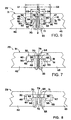
- the locking ring assembly 29 is shown installed in the terminal ends 42 and 43 of the locking ring 31 three different configurations: an unflexed configuration, a flexed contracted configuration, and a flexed expanded configuration, respectively.
- the circumferential span L1 between outer circumferential walls 80 and 81 i.e., the circumferential span of the recesses 46 and 47 and the space D
- the outer circumferential span K1 of the retaining key 32 i.e., from one outer face 90 to another outer face 91 of the retaining key 32
- the circumferential span L2 between inner circumferential walls 84 and 85 is less than the inner circumferential span K2 of the retaining key 32 (i.e., from one inner face 94 to another inner face 95 of the retaining key 32), thus providing gaps G3 and G4.
- the circumferential gaps G1 and G2 provide a range over which the terminal ends 42 and 43 of the locking ring 31 can move circumferentially towards one another and, consequently, a range over which the locking ring 31 can contract relative to its unflexed configuration.
- Fig. 7 shows the locking ring assembly 29 in its fully flexed contracted configuration; that is, where the faces 90 and 91 of the retaining key 32 prevent further circumferentially inward movement of the outer walls 80 and 81 of the recesses 46 and 47.
- the circumferential gaps G3 and G4 provide a range over which the terminal ends 42 and 43 of the locking ring 31 can move circumferentially away from one another and, consequently, a range over which the locking ring 31 can expand relative to its unflexed configuration.
- Fig. 8 shows the locking ring assembly 29 in its fully flexed expanded configuration; that is, where the faces 94 and 95 of the retaining key 32 prevent further circumferentially outward movement of the inner walls 84 and 85 of the recesses 46 and 47.
- the gaps G1, G2, G3 and G4 enable the locking ring 31 to expand and contract a predetermined amount.
- the locking ring 31 may contract, for example, to accommodate differences in tolerances in the groove 21 of the wheel base 10. Also, when the locking ring 31 is subjected to centrifugal forces, for example when the wheel rim assembly 8 reaches high speeds, the locking ring 31 may flex outwardly over the range provided by the gaps G3 and G4.
- the locking ring assembly 29 does not have any loose parts.
- the clip 33 maintains a constant biasing load on the retaining key 31 in the recesses 46 and 47 and thus reduces or prevents chatter or the like of the retaining key 31 within the recesses 46 and 47. This biasing load is maintained whether the locking ring 31 is in an unflexed or flexed configuration.
- the locking ring assembly 29 is simple to install. To install the locking ring assembly 29, the locking ring 31 is circumferentially enlarged and placed over the cylindrical portion 19 of the wheel base 10 ( Fig. 1 ). Upon release, the locking ring 31 springs back for seating into the annular groove 21. The retaining key 32 is then inserted into the recesses 46 and 47 to bridge the space D therebetween and therefore connect the terminal ends 42 and 43 of the locking ring 31. The two opposite end portions 70 and 71 of the clip 33 are then inserted into the respective holes 74 and 75 in the thinner portion 34.
- the connecting portion 79 of the intermediate section 72 is raised against the biasing force in the clip 33 so that the connecting portion 79 will "clear" the retaining key 32.
- the opposite end portions 70 and 71 may then be fully inserted into the holes 74 and 75, whereupon the intermediate section 72, in attempting to spring back to its unflexed configuration, engages the radially outer surface 78 of the retaining key 32 to secure the retaining key 32 in the recesses 46 and 47.
- the wheel rim member 11 is then moved relative to the wheel base 10 in the manner described above, whereby the locking ring 31 firmly secures the wheel rim member 11 on the wheel base 10. Accordingly, the locking ring assembly 29 does not require special tools for installation. Moreover, there is no tedious twisting of wires involved, as in some prior art mechanisms.
- substantially the entire locking ring assembly 29 is between the wheel base 10 and wheel rim member 11.
- the retaining key 32 which is disposed within recesses 46 and 47 of the locking ring 31, is free from being bumped or damaged.
Landscapes
- Engineering & Computer Science (AREA)
- Mechanical Engineering (AREA)
- Snaps, Bayonet Connections, Set Pins, And Snap Rings (AREA)
Claims (12)
- Verriegelungsringvorrichtung (29) für eine Radnabenvorrichtung (8), wobei die Verriegelungsringvorrichtung einen Verriegelungsring (31) mit querverlaufender Teilung aufweist, die im Umfangsrichtung einander entgegengesetzte Abschlussenden (42,43) bildet, wobei die Abschlussenden (42,43) jeweils radial nach außen offene Vertiefungen (56,57) aufweisen;
gekennzeichnet durch
einen Halteriegel (32) zum Gegeneinanderhalten der Abschlussenden des Verriegelungsrings, wobei der Halteriegel einander entgegengesetzte Endteile (62,63) aufweist, die jeweils in den radial nach außen offenen Vertiefungen der betreffenden Abschlussenden des Verriegelungsrings aufgenommen und in Umfangsrichtung in diesen Vertiefungen rückgehalten sind; und
einen Clip (33) zum Zusammengreifen mit dem Halteriegel (32) und zum Verhindern einer radial nach außen gerichteten Bewegung des Halteriegels aus den Vertiefungen (56,57). - Verriegelungsringvorrichtung nach Anspruch 1, bei der der Halteriegel (32) in Querrichtung erweiterte Endrückhalteteile (62,63) und einen zwischen diesen angeordneten Brückenteil (64) mit reduzierter Breite aufweist, und die Vertiefungen (56,57) entsprechende vergrößerte Endbereiche (52,53) zur radialen Aufnahme der betreffenden erweiterten Endrückhalteteile und Teile mit reduzierter Breite zur radialen Aufnahme des mit reduzierter Breite ausgebildeten Brückenteils aufweisen.
- Verriegelungsringvorrichtung nach Anspruch 2, bei der die Abschlussenden (42,43) des Verriegelungsrings (31) in Umfangsrichtung voneinander beabstandet sind und der Brückenteil (64) des Halteriegels (32) den Raum zwischen den vergrößerten Vertiefungs-Endbereichen überspannt.
- Verriegelungsringvorrichtung nach Anspruch 3, bei der mindestens eines der erweiterten Endrückhalteteile (62,63) des Halteriegels (32) in Umfangsrichtung kleiner ist als der vergrößerte Endbereich (52,53) der betreffenden Vertiefung, wodurch die Bewegung des Halteriegels (32) auf eine begrenzte Umfangsbewegung relativ zu dem Verriegelungsring eingeschränkt wird.
- Verriegelungsringvorrichtung nach Anspruch 1, bei der der Clip (33) eine Feder mit einem mit dem Verriegelungsring (31) zusammengreifenden ersten Teil (66) und einem mit dem Halteriegel (32) zusammengreifenden zweiten Teil (67) ist und der erste und der zweite Teil aufeinander hin vorgespannt sind.
- Verriegelungsringvorrichtung nach Anspruch 5, bei der der Clip (33) aus einer fortlaufenden Drahtlänge hergestellt ist, die einen Mittelabschnitt (72), der den zweiten Teil (67) bildet, und einander gegenüberliegende Endabschnitte (70,71) aufweist, die den ersten Teil (66) bilden.
- Verriegelungsringvorrichtung nach Anspruch 6, bei der die einander gegenüberliegenden Endabschnitte (70,71) in jeweiligen Axiallöchern (74,75) in dem Verriegelungsring (31) angeordnet sind und der Mittelabschnitt (72) über den Halteriegel (32) vorsteht.
- Verriegelungsringvorrichtung nach Anspruch 6, bei der der Mittelabschnitt (72) des Clips (33) in sich derart zurückgebogen ist, dass er ein Paar von Schenkeln bildet, die über ein Verbindungsteil (79) miteinander verbunden sind, und das Verbindungsteil radial derart gebogen ist, dass es eine axiale Seitenfläche des Halteriegels (32) überlappt, wodurch der Clip in Position gehalten ist.
- Verriegelungsringvorrichtung nach Anspruch 8, bei der die Vertiefungen (56,57) entsprechende Vertiefungsbereiche mit reduzierter Breite aufweisen, die zusammen den mit reduzierter Breite ausgebildeten Brückenteil (64) radial aufnehmen, und bei der die Axiallöcher (74,75) in die Vertiefungsbereiche mit reduzierter Breite ausmünden, und die einander gegenüberliegenden Endabschnitte (70,71) des Clips (33) sich durch die Axiallöcher hindurch und über den Halteriegel (32) hinaus erstrecken, um eine radial nach außen verlaufende Bewegung des Halteriegels aus den Vertiefungen (56,57) heraus zu verhindern.
- Verriegelungsringvorrichtung nach Anspruch 1, bei der der Clip (33) als ein elastischer Aufdrückclip (33) ausgebildet ist, der einen ersten Arm (66) zum Zusammengreifen mit mindestens einem Abschlussende (42,43) des Verriegelungsrings (31) und einen elastisch zu dem ersten Arm vorgespannten zweiten Arm (67) zum Zusammengreifen mit dem Halteriegel (32) und zum Halten desselben in den Vertiefungen (56,57) aufweist.
- Radfelgenvorrichtung mit einer Achse, mit:einer Radbasis (10);einem abnehmbaren Radfelgenteil (11);einem Verriegelungsring (31) mit einer querverlaufenden Unterbrechung, die im Umfangsrichtung einander entgegengesetzte Abschlussenden (42,43) bildet, wobei der Verriegelungsring in einer Nut (20) der Radbasis (10) aufgenommen ist, um das Radfelgenteil an der Radbasis zu sichern, und die Abschlussenden jeweils radial nach außen offene Vertiefungen (56,57) aufweisen;gekennzeichnet durcheinen Halteriegel (32) mit einander entgegengesetzten Endteilen (62, 63), die jeweils in den radial nach außen offenen Vertiefungen der betreffenden Abschlussenden des Verriegelungsrings aufgenommen und in Umfangsrichtung in diesen Vertiefungen rückgehalten sind, um die Abschlussenden (42,43) des Verriegelungsrings gegeneinanderzuhalten; undeinen Clip (33) zum Zusammengreifen mit dem Halteriegel (32) und zum Verhindern einer radial nach außen verlaufenden Bewegung des Halteriegels aus den Vertiefungen (56,57) heraus.
- Verfahren zum Installieren eines Verriegelungsrings (31) in einer Radbasis (10), mit folgendem Schritt:Einsetzen des Verriegelungsrings (31) in eine in der Radbasis ausgebildete Nut (20), wobei der Verriegelungsring (31) eine querverlaufende Unterbrechung aufweist, die im Umfangsrichtung entgegengesetzte Abschlussenden (42,43) bildet, und wobei die Abschlussenden jeweils radial nach außen offene Vertiefungen (56,57) aufweisen;gekennzeichnet durch folgende Schritte:Einführen eines einander entgegengesetzte Endteile (62,63) aufweisenden Halteriegels (32) in die jeweiligen nach außen offenen Vertiefungen (56,57);axiales Einführen eines ersten Teils (66) eines Clips (33) in ein Axialloch (74) des Verriegelungsrings (31);Biegen eines zweiten Teils (67) des Clips relativ zu dem ersten Teil des Clips, wobei die ersten und zweiten Teile aufeinander hin vorgespannt werden;Bewegen des zweiten Teils (67) über den Halteriegel (32) hinaus; undFreigeben des zweiten Teils (67), wodurch der zweite Teil mit dem Halteriegel zusammengreift, um eine radial nach außen verlaufende Bewegung des Halteriegels aus den Vertiefungen (56,57) heraus zu verhindern.
Applications Claiming Priority (3)
| Application Number | Priority Date | Filing Date | Title |
|---|---|---|---|
| US35397102P | 2002-01-31 | 2002-01-31 | |
| US353971P | 2002-01-31 | ||
| PCT/US2003/002736 WO2003064183A1 (en) | 2002-01-31 | 2003-01-30 | Locking ring assembly for wheel rim assembly |
Publications (2)
| Publication Number | Publication Date |
|---|---|
| EP1472103A1 EP1472103A1 (de) | 2004-11-03 |
| EP1472103B1 true EP1472103B1 (de) | 2008-03-26 |
Family
ID=27663271
Family Applications (1)
| Application Number | Title | Priority Date | Filing Date |
|---|---|---|---|
| EP03707605A Expired - Lifetime EP1472103B1 (de) | 2002-01-31 | 2003-01-30 | Sicherungsringvorrichtung für eine radnabenvorrichtung |
Country Status (4)
| Country | Link |
|---|---|
| US (1) | US6786259B2 (de) |
| EP (1) | EP1472103B1 (de) |
| DE (1) | DE60319953T2 (de) |
| WO (1) | WO2003064183A1 (de) |
Families Citing this family (20)
| Publication number | Priority date | Publication date | Assignee | Title |
|---|---|---|---|---|
| FR2883803B1 (fr) | 2005-04-05 | 2007-05-18 | Michelin Soc Tech | Systeme de verouillage d'un anneau de montage sur un moyeu de vehicule |
| FR2883802B1 (fr) * | 2005-04-05 | 2007-05-18 | Michelin Soc Tech | Anneau de verrouillage dans un ensemble de montage d'un pneumatique sur un moyeu de vehicule |
| US8199653B2 (en) | 2006-08-22 | 2012-06-12 | Embarq Holdings Company, Llc | System and method for communicating network performance information over a packet network |
| JP2008222207A (ja) * | 2007-02-13 | 2008-09-25 | Topy Ind Ltd | 多片リムおよびその脱着方法 |
| JP2009062040A (ja) * | 2007-08-14 | 2009-03-26 | Topy Ind Ltd | ロックリングの着脱治具 |
| US9079456B2 (en) | 2007-08-14 | 2015-07-14 | Topy Kogyo Kabushiki Kaisha | Lock ring mounting/demounting jig |
| GB2480817A (en) * | 2010-06-01 | 2011-12-07 | Gkn Offhighway Ltd | A vehicle wheel |
| US8833694B2 (en) * | 2011-06-14 | 2014-09-16 | Neal Gilleran | Split circumference aircraft wheel assembly with integrated drive motor assembly |
| GB2516598B (en) * | 2012-05-02 | 2019-01-09 | Borealis Tech Ltd | Aircraft wheel bearing arrangement |
| US10464372B2 (en) | 2012-09-20 | 2019-11-05 | Gkn Armstrong Wheels, Inc. | Lock ring spreader |
| US20150007919A1 (en) * | 2013-01-31 | 2015-01-08 | Wu Xi Jidaer Wheel Co., Ltd. | Hinged type locking ring quick locking device |
| US10046598B2 (en) * | 2013-03-15 | 2018-08-14 | Fredrick Taylor | Wheel rim |
| FR3015951B1 (fr) * | 2013-12-31 | 2017-10-06 | Messier Bugatti Dowty | Jante de roue d'aeronef a talon amovible. |
| CN104816581A (zh) * | 2015-01-29 | 2015-08-05 | 上海翎铠国际贸易有限公司 | 大型载重车辆隼卯凹凸槽轮辋锁圈 |
| US11167588B2 (en) * | 2015-04-24 | 2021-11-09 | Gkn Armstrong Wheels, Inc. | Wheel assembly with low profile outboard driver locking arrangement |
| US20170136815A1 (en) * | 2015-11-16 | 2017-05-18 | Caterpillar Inc. | Driver keys for use with wheel rims |
| US10350940B2 (en) | 2016-03-22 | 2019-07-16 | Parker-Hannifin Corporation | Aircraft wheel assembly |
| US10226962B2 (en) | 2016-12-05 | 2019-03-12 | Honeywelll International Inc. | Vehicle wheel including antirotation plate |
| AU2020376913A1 (en) * | 2019-10-31 | 2022-05-19 | Otr Wheel Engineering, Inc. | Wheel assembly, lock-ring for wheel assembly, handle engageable with lock-ring, and related methods |
| USD981316S1 (en) | 2019-10-31 | 2023-03-21 | Otr Wheel Engineering, Inc. | Wheel lock ring assembly |
Family Cites Families (9)
| Publication number | Priority date | Publication date | Assignee | Title |
|---|---|---|---|---|
| US2361330A (en) * | 1941-12-22 | 1944-10-24 | Nathaniel B Stone | Tire retaining ring |
| US4209052A (en) * | 1978-10-23 | 1980-06-24 | Goodyear Aerospace Corporation | Wheel flange retaining ring |
| US4552194A (en) * | 1984-06-11 | 1985-11-12 | Goodyear Aerospace Corporation | Locking configuration for a wheel rim flange retaining ring |
| US4683930A (en) * | 1985-10-31 | 1987-08-04 | Goodyear Aerospace Corporation | Locking configuration for a wheel rim flange retaining ring |
| US4635695A (en) * | 1985-10-31 | 1987-01-13 | Goodyear Aerospace Corporation | Locking configuration for a wheel rim flange retaining ring |
| JPS6445502U (de) * | 1987-09-17 | 1989-03-20 | ||
| US5086821A (en) * | 1990-01-23 | 1992-02-11 | The B. F. Goodrich Company | Aircraft wheel |
| US5259430A (en) * | 1991-11-27 | 1993-11-09 | Aircraft Braking Systems Corporation | Configuration for demountable wheel rim flange/split lockring assemblies |
| JP2000108603A (ja) * | 1998-08-07 | 2000-04-18 | Topy Ind Ltd | 多片リムディスクホイ―ルとその製造方法 |
-
2003
- 2003-01-30 US US10/354,924 patent/US6786259B2/en not_active Expired - Lifetime
- 2003-01-30 DE DE60319953T patent/DE60319953T2/de not_active Expired - Fee Related
- 2003-01-30 WO PCT/US2003/002736 patent/WO2003064183A1/en not_active Ceased
- 2003-01-30 EP EP03707605A patent/EP1472103B1/de not_active Expired - Lifetime
Also Published As
| Publication number | Publication date |
|---|---|
| US6786259B2 (en) | 2004-09-07 |
| DE60319953D1 (de) | 2008-05-08 |
| WO2003064183A1 (en) | 2003-08-07 |
| DE60319953T2 (de) | 2009-04-02 |
| EP1472103A1 (de) | 2004-11-03 |
| US20030168143A1 (en) | 2003-09-11 |
Similar Documents
| Publication | Publication Date | Title |
|---|---|---|
| US6786259B2 (en) | Locking ring assembly for wheel rim assembly | |
| CA2791465C (en) | Rotatable bar pin bushing assembly | |
| US6682151B1 (en) | Wheel cover retention apparatus | |
| US6190260B1 (en) | Tripod universal joint and method of its manufacture | |
| US11787230B2 (en) | Vehicle wheel cover retention system | |
| CA1281196C (en) | Axial retaining member and method for interconnecting male and female splined members | |
| EP1401665B1 (de) | Verfahren zur befestigung einer lagerung einer radnabe in einer kraftfahrzeugaufhängung | |
| GB2270127A (en) | Split-type bearing assembly eg for a crankshaft. | |
| US6796582B2 (en) | Assembly consisting of an inflator, a housing and a retainer | |
| JPS62227802A (ja) | ホイ−ルリム組立体 | |
| CN113825646B (zh) | 用于车轮的插入元件和具有至少一个这种插入元件的车轮 | |
| US4760860A (en) | Valve for tubeless tire | |
| US4470637A (en) | Vehicle wheel with segmental rim parts and retaining ring | |
| EP0721401B1 (de) | Korrosionsdichtung für abnehmbares felgenhorn eines flugzeugmotors | |
| EP0573236B1 (de) | Verbesserungen an Bremsscheiben | |
| EP1697151B1 (de) | Run-flat-stützring mit verbesserten befestigungsmerkmalen | |
| US4459119A (en) | Lock washer for spring type retainer rings | |
| US4768838A (en) | Wheel cap | |
| US4566515A (en) | Wheel and solid tire assembly having locking ring | |
| US4943122A (en) | Center hub cap for vehicle wheels | |
| EP0215598B1 (de) | Am Rad angeordnete Scheiben | |
| EP0215597A1 (de) | Am Rad angeordnete Scheiben | |
| US4262967A (en) | Wheel trim retainer | |
| JP2001239814A (ja) | 空気入りタイヤ用の支持中子及びその組立方法 | |
| CA1308431C (en) | Center hub cap for vehicle wheels |
Legal Events
| Date | Code | Title | Description |
|---|---|---|---|
| PUAI | Public reference made under article 153(3) epc to a published international application that has entered the european phase |
Free format text: ORIGINAL CODE: 0009012 |
|
| 17P | Request for examination filed |
Effective date: 20040827 |
|
| AK | Designated contracting states |
Kind code of ref document: A1 Designated state(s): AT BE BG CH CY CZ DE DK EE ES FI FR GB GR HU IE IT LI LU MC NL PT SE SI SK TR |
|
| AX | Request for extension of the european patent |
Extension state: AL LT LV MK RO |
|
| 17Q | First examination report despatched |
Effective date: 20050427 |
|
| GRAP | Despatch of communication of intention to grant a patent |
Free format text: ORIGINAL CODE: EPIDOSNIGR1 |
|
| GRAS | Grant fee paid |
Free format text: ORIGINAL CODE: EPIDOSNIGR3 |
|
| GRAA | (expected) grant |
Free format text: ORIGINAL CODE: 0009210 |
|
| AK | Designated contracting states |
Kind code of ref document: B1 Designated state(s): DE FR GB |
|
| REG | Reference to a national code |
Ref country code: GB Ref legal event code: FG4D |
|
| REF | Corresponds to: |
Ref document number: 60319953 Country of ref document: DE Date of ref document: 20080508 Kind code of ref document: P |
|
| ET | Fr: translation filed | ||
| PLBE | No opposition filed within time limit |
Free format text: ORIGINAL CODE: 0009261 |
|
| STAA | Information on the status of an ep patent application or granted ep patent |
Free format text: STATUS: NO OPPOSITION FILED WITHIN TIME LIMIT |
|
| 26N | No opposition filed |
Effective date: 20081230 |
|
| PGFP | Annual fee paid to national office [announced via postgrant information from national office to epo] |
Ref country code: DE Payment date: 20090302 Year of fee payment: 7 |
|
| PG25 | Lapsed in a contracting state [announced via postgrant information from national office to epo] |
Ref country code: DE Free format text: LAPSE BECAUSE OF NON-PAYMENT OF DUE FEES Effective date: 20100803 |
|
| REG | Reference to a national code |
Ref country code: FR Ref legal event code: PLFP Year of fee payment: 14 |
|
| REG | Reference to a national code |
Ref country code: FR Ref legal event code: PLFP Year of fee payment: 15 |
|
| REG | Reference to a national code |
Ref country code: FR Ref legal event code: PLFP Year of fee payment: 16 |
|
| PGFP | Annual fee paid to national office [announced via postgrant information from national office to epo] |
Ref country code: FR Payment date: 20201217 Year of fee payment: 19 Ref country code: GB Payment date: 20201218 Year of fee payment: 19 |
|
| GBPC | Gb: european patent ceased through non-payment of renewal fee |
Effective date: 20220130 |
|
| PG25 | Lapsed in a contracting state [announced via postgrant information from national office to epo] |
Ref country code: GB Free format text: LAPSE BECAUSE OF NON-PAYMENT OF DUE FEES Effective date: 20220130 |
|
| PG25 | Lapsed in a contracting state [announced via postgrant information from national office to epo] |
Ref country code: FR Free format text: LAPSE BECAUSE OF NON-PAYMENT OF DUE FEES Effective date: 20220131 |