EP1472113B1 - Trägerturm - Google Patents
Trägerturm Download PDFInfo
- Publication number
- EP1472113B1 EP1472113B1 EP03702070A EP03702070A EP1472113B1 EP 1472113 B1 EP1472113 B1 EP 1472113B1 EP 03702070 A EP03702070 A EP 03702070A EP 03702070 A EP03702070 A EP 03702070A EP 1472113 B1 EP1472113 B1 EP 1472113B1
- Authority
- EP
- European Patent Office
- Prior art keywords
- tower
- cover member
- crossbar
- base portion
- tower portion
- Prior art date
- Legal status (The legal status is an assumption and is not a legal conclusion. Google has not performed a legal analysis and makes no representation as to the accuracy of the status listed.)
- Expired - Lifetime
Links
- 230000000295 complement effect Effects 0.000 description 5
- 239000000428 dust Substances 0.000 description 2
- 238000010276 construction Methods 0.000 description 1
- 238000011109 contamination Methods 0.000 description 1
- 230000003993 interaction Effects 0.000 description 1
- 230000000284 resting effect Effects 0.000 description 1
Images


Classifications
-
- B—PERFORMING OPERATIONS; TRANSPORTING
- B60—VEHICLES IN GENERAL
- B60R—VEHICLES, VEHICLE FITTINGS, OR VEHICLE PARTS, NOT OTHERWISE PROVIDED FOR
- B60R9/00—Supplementary fittings on vehicle exterior for carrying loads, e.g. luggage, sports gear or the like
- B60R9/04—Carriers associated with vehicle roof
- B60R9/045—Carriers being adjustable or transformable, e.g. expansible, collapsible
Definitions
- the present invention relates to a sports equipment rack for a vehicle. More particularly, the present invention provides a rack tower configured to be attached to a vehicle roof rail.
- Sports equipment racks for vehicles typically include one or more crossbars configured to extend across a vehicle roof for supporting recreational equipment items over the roof.
- each crossbar is attached to the car roof via a pair of towers.
- the towers serve both to couple the crossbar to the vehicle, and to support the crossbars over the vehicle roof so that the crossbars do not contact the roof.
- rack towers are known, and may be configured to be attached to a vehicle roof in any of a number of different ways.
- some rack towers are configured to be attached to vehicle roof rails.
- Roof rails are long, narrow, rail-shaped devices mounted to the roofs of many vehicles, often by the vehicle manufacturer.
- a vehicle with roof rails typically has a plurality of rails that run at least partially along the length of the roof in a parallel relation to one another.
- Roof rails generally include a slotted track that contains one or more mounts or connectors. These connectors are typically configured to accept a fastener, such as a bolt, to allow the attachment of items such as rack towers to the roof rail, and thus to the vehicle.
- Rack towers that mount to roof rails offer some advantages over other types of towers.
- these towers may be mounted to vehicles that lack rain gutters or other features commonly used for mounting rack towers.
- these towers typically are supported completely by the roof rails, and do not otherwise touch the vehicle roof.
- known rack towers for mounting to a roof rail may also present some shortcomings.
- these towers are typically configured to remain at a fixed angle to the roof once the tower is adjusted for a particular roof. In this situation, a user may need to exercise care when mounting or removing the rack from the vehicle roof to avoid damaging the roof rails by lifting one tower while the other is attached to the vehicle.
- the bolts used to mount the towers to the fasteners inside the rail slots are typically not accessible when the tower portion is mounted to the base portion. In this case, the tower portions typically must be removed from the base portions to adjust the position of the rack on the vehicle roof.
- US6,010,048 discloses a roof rack, according to the preamble of claim 1, with quick release tower assembly comprising a base portion for attachment to a vehicle and a tower portion having a holding mechanism for securing a portion of a crossbar.
- a quick release mechanism allows a user to selectively lock and release the tower body in place on the base by means of a pivoting handle which engages directly with the base.
- the present invention provides a rack tower according to claim 1 and configured to be mounted to a roof rail of a vehicle that may avoid the problems encountered with conventional towers.
- the invention is defined in the appended claims. The advantages of the present invention will be understood more readily after a consideration of the drawings and the Detailed Description of the Preferred Embodiments.
- Fig. 1 shows, generally at 10, a rack tower according to a first embodiment of the present invention, coupled to a vehicle roof rail 12.
- Rack tower 10 includes a base 14 and a tower portion 16.
- Base 14 is configured to be mounted to one or more connectors disposed within a slot 18 formed in roof rail 12.
- Tower portion 16 is configured to be coupled to base 14, and also to retain a crossbar 20, to thus couple the crossbar to the vehicle.
- Fig. 2 shows the construction of rack tower 10 in more detail.
- Base 14 includes one or more bolt holes 22 (two are shown) configured to accept bolts 24 to secure the base to the connectors disposed within slot 18 of roof rail 12.
- Base 14 also includes an inner surface 26 against which tower portion 16 may rest when coupled to base 14.
- Inner surface 26 is typically configured to have a shape complementary to the shape of the bottom surface of tower portion 16.
- inner surface 26 has a continuously curved shape that allows tower portion 16 to pivot relative to base 14, as described in more detail below. This allows one side of crossbar 20 to be lifted without damaging the roof rail to which the other side of the crossbar is attached, and also allows crossbar 20 to be more easily adapted for use on roofs of different profiles.
- inner surface 26 may have any other suitable shape without departing from the scope of the present invention.
- Base 14 also includes a pair of recesses 28.
- Recesses 28 are configured to receive of a pair of complementary locking pins 30 that are movably coupled to tower portion 16.
- Locking pins 30 are movable between a retracted position, in which the locking pins do not extend into recesses 28, and an extended position, in which the locking pins do extend into the recesses. This allows tower portion 16 to be mounted to base 14 simply by resting the tower portion against inner surface 26 of base 14, and then moving locking pins 30 into recesses 28. Likewise, tower portion 16 may be removed from base 14 simply by moving locking pins 30 out of recesses 28, and then removing the tower portion from the base. The operation of locking pins 30 is described in more detail below.
- Tower portion 16 includes a body 32 and a tower cover 34.
- Body 32 typically includes an aperture 36 configured to accommodate crossbar 20, and also may include a wedge 38 that is adjustable via bolt 40 to grip or clamp crossbar 20 within aperture 36.
- Body 32 also includes a pair of generally cylindrical locking pin mounts 42.
- the depicted locking pin mounts 42 have a generally curved shape that is configured to be complementary to the shape of inner surface 26 of base 14 to facilitate the pivoting of tower portion 16 on the base.
- the locking pin mounts 42 may have any other suitable shape without departing from the scope of the present invention.
- Locking pin mounts 42 are each configured to hold a locking pin sleeve 44 firmly in position relative to body 32. As shown in Fig. 2, one locking pin sleeve 44 is shown separate from body 32, while the other locking pin sleeve 44 is shown positioned within locking pin mount 42.
- Each locking pin sleeve 44 has a threaded inner surface that is complementary to threads 46 formed in each locking pin 30. The interaction of threads 46 on locking pins 30 with the threads on the inner surfaces of locking pin sleeves 44 causes locking pins 30 to move linearly along their axis of rotation 51 relative to locking pin sleeves 44 when the locking pins are rotated. Thus, locking pins 30 can be made to retract into or extend out of locking pin sleeves 4,4 by rotating the locking pins with respect to the locking pin sleeves.
- tower cover 34 includes a downwardly extending locking pin bracket 48.
- Locking pin bracket 48 is configured to accommodate a flattened (or otherwise shaped) portion 49 at the end of each locking pin 30.
- Locking pin bracket 48 is also configured to allow locking pins 30 to slide linearly along the inner surfaces of the bracket, but not to rotate with respect to the bracket.
- Bracket cover 50 configured to snap onto the bracket may be used to retain ends 49 of locking pins 30 within the bracket.
- Bracket cover 50 may include a lower surface complementary in shape to the inner surface 26 of base 14. This, combined with the ability of locking pins 30 to rotate within locking pin sleeves 44, allows tower cover 34 to be pivoted between an open position and a closed position with respect to body 32. Tower cover 34 pivots along an axis of rotation 51 that extends generally through both locking pins 30.
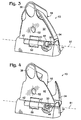
- the closed position is illustrated in Figs. 3, 5 and 6, and the open position is illustrated in Figs. 4, 7 and 8.
- the base is shown in phantom in Figs. 5-8, while the positions of locking pins 30 are indicated in dashed lines in these Figs.
- Figs. 3-8 show operation of the rack tower from a perspective view
- Figs. 5-8 show the operation of the rack tower from side and front views.
- bracket 48 causes locking pins 30 to rotate along with the tower cover 34.
- the threads within locking pin sleeves 44 then cause locking pins 30 to retract into the sleeves as the locking pins rotate.
- Locking pins 30 may retract completely into locking pin sleeves 44 when tower cover 34 is opened far enough, as shown in Fig. 4. This allows tower portion 16 to be easily removed from base 14.
- tower portion 16 may be coupled to base 14 simply by placing the tower portion 16 upon inner surface 26 of base while tower cover 34 is in the open position, and then pivoting the tower cover to the closed position.
- tower cover 34 Besides providing for the quick attachment of tower portion 16 to base 14, the use of tower cover 34 also offers other advantages over conventional rack towers. For example, tower cover 34 covers much of the hardware used to mount and adjust rack tower 10 when in the closed position. Thus, mounting bolts 24 and wedge adjustment bolt 40 are protected from contamination by road dust and dirt when tower cover 34 is closed. This may keep the bolts operating smoothly for a longer period of time compared to unprotected bolts.
- tower cover 34 may include a lock mount 52 configured to accept the attachment of a locking mechanism (not shown).
- the locking mechanism When installed on rack tower 10, the locking mechanism may be locked by a user to prevent others from opening tower cover 34. Because mounting bolts 24 and wedge adjustment bolt 40 are completely covered when tower cover 34 is closed, locking the locking mechanism prevents the mounting or adjustment bolts from being tampered with, and thus may help to prevent the theft of rack tower 10 or crossbar 20. It will be appreciated that mounting bolts 24 and wedge adjustment bolt 40 are all easily accessible by a user when tower cover 34 is in the open position (mounting bolts 24 are accessible through access holes 54 in body 32), without any need to remove tower portion 16 from base 14.
Landscapes
- Engineering & Computer Science (AREA)
- Mechanical Engineering (AREA)
- Fittings On The Vehicle Exterior For Carrying Loads, And Devices For Holding Or Mounting Articles (AREA)
- Transmission Devices (AREA)
- Bridges Or Land Bridges (AREA)
- Magnetic Resonance Imaging Apparatus (AREA)
- Refuge Islands, Traffic Blockers, Or Guard Fence (AREA)
Claims (14)
- Tragvorrichtung zum Befestigen eines Abschnitts einer Querstange (20) an der Oberseite eines Autos miteinem Basisteil (14), das einen Mechanismus zum Befestigen des Basisteils (14) an einem Auto hat, undeinem Turmteil (16), das mit dem Basisteil (14) verbunden ist und einen Haltemechanismus (36) zum Befestigen eines Abschnitts einer Querstange (20) hat, wobei das Turmteil (16) in Bezug auf das Basisteil (14) schwenkbar ist, um eine Anpassung an verschiedene Dachausgestaltungen zu ermöglichen, dadurch gekennzeichnet, dass das Turmteil (16) ferner ein Abdeckelement (34) aufweist, das zwischen einer offenen und einer geschlossenen Position bewegbar ist, wobei eine Bewegung des Abdeckelements (34) einen verriegelnden Eingriff des Turmteils (16) in dem Basisteil (14) bewirkt, wobei das Turmteil (16) einen oder mehrere Verriegelungsstifte (30) aufweist, die in der Richtung der Schwenkachse verlaufen, wenn sich das Abdeckelement (34) von der offenen in die geschlossene Position bewegt.
- Vorrichtung nach Anspruch 1, bei der das Basisteil (14) einen Befestigungsmechanismus (38) zum Befestigen des Basisteils (14) an einer Schiene an der Oberseite eines Autos hat.
- Vorrichtung nach Anspruch 1 oder Anspruch 2, bei der das Abdeckelement (34) zwischen der offenen und der geschlossenen Position schwenkt.
- Vorrichtung nach einem der vorhergehenden Ansprüche, bei der der Befestigungsmechanismus (38) zugänglich ist, wenn sich das Abdeckelement (34) in der offenen Position befindet, und unzugänglich ist, wenn sich das Abdeckelement (34) in der geschlossenen Position befindet.
- Vorrichtung nach einem der vorhergehenden Ansprüche, die ferner eine mit dem Turmteil (16) verbundene Verriegelungsvorrichtung aufweist, um es einem Benutzer zu erlauben, das Abdeckelement (34) in der geschlossenen Position zu verriegeln.
- Vorrichtung nach einem der vorhergehenden Ansprüche, bei der das Basisteil (14) eine oder mehrere Aussparungen aufweist, wobei der eine oder die mehreren Verriegelungsstifte (30) dazu in der Lage ist bzw. sind, sich in Eingriff mit dem einen oder den mehreren Aussparungen zu bewegen, wenn sich das Abdeckelement (34) von der offenen Position in die geschlossene Position bewegt.
- Vorrichtung nach Anspruch 6, bei der das Abdeckelement (34) um eine Achse schwenkt, was ein Ausfahren oder ein Zurückziehen des einen oder der mehreren Verriegelungsstifte (30) in die oder aus den Aussparungen bewirkt.
- Vorrichtung nach einem der vorhergehenden Ansprüche, bei der das Turmteil (16) ferner eine Klemmvorrichtung (38), die zum Greifen der Querstange (20) ausgestaltet ist, und einen Einstellmechanismus (40) zum Festziehen und Lösen der Klemmvorrichtung (38) in Bezug auf die Querstange (20) aufweist.
- Vorrichtung nach einem der Ansprüche 1 bis 7, bei der der Haltemechanismus (36) eine Klemmvorrichtung (38) und einen Einstellmechanismus (40) zum Festziehen und Lösen der Klemmvorrichtung (38) in Bezug auf eine Querstange (20) enthält.
- Vorrichtung nach Anspruch 8 oder 9, bei der der Einstellmechanismus (40) zugänglich ist, wenn das Abdeckelement (34) offen ist, und unzugänglich ist, wenn das Abdeckelement (34) geschlossen ist.
- Vorrichtung nach einem der Ansprüche 8 bis 10, bei der der Einstellmechanismus (40) über ein mit einem Gewinde versehenes Element betätigt werden kann, das im Wesentlichen senkrecht zu der Querstange (20) ausgerichtet ist.
- Vorrichtung nach einem der Ansprüche 8 bis 10, bei der der Einstellmechanismus (40) ein mit einem Gewinde versehenes Element enthält, das auf ein Keilelement trifft, das die Querstange (20) berührt und festklemmt, wenn das mit einem Gewinde versehene Element in eine Bohrung in dem Turmteil (16) geschraubt wird.
- Trägersystem zum Tragen von Gegenständen an einem Auto, das mit einem Paar Schienen (12) an der Oberseite des Autos ausgestattet ist, wobei das Trägersystem zumindest ein Paar Tragvorrichtungen aufweist, wie sie in einem der vorhergehenden Ansprüche definiert sind, wobei jede dieser Tragvorrichtungen zum Befestigen einer dieser Tragvorrichtungen an jeder Schiene (12) und Befestigen einer Querstange (20) zwischen den Tragvorrichtungen ausgestaltet ist, wobei das Basisteil von jeder dieser Tragvorrichtungen zur Befestigung an einer der Schienen (12) ausgestaltet ist.
- Träger nach Anspruch 13, bei dem die Oberseite des Autos ein Dach ist.
Applications Claiming Priority (3)
| Application Number | Priority Date | Filing Date | Title |
|---|---|---|---|
| US34881702P | 2002-01-11 | 2002-01-11 | |
| US348817P | 2002-01-11 | ||
| PCT/US2003/000864 WO2003059692A1 (en) | 2002-01-11 | 2003-01-10 | Rack tower |
Publications (3)
| Publication Number | Publication Date |
|---|---|
| EP1472113A1 EP1472113A1 (de) | 2004-11-03 |
| EP1472113A4 EP1472113A4 (de) | 2005-02-23 |
| EP1472113B1 true EP1472113B1 (de) | 2007-10-24 |
Family
ID=23369673
Family Applications (1)
| Application Number | Title | Priority Date | Filing Date |
|---|---|---|---|
| EP03702070A Expired - Lifetime EP1472113B1 (de) | 2002-01-11 | 2003-01-10 | Trägerturm |
Country Status (5)
| Country | Link |
|---|---|
| EP (1) | EP1472113B1 (de) |
| AT (1) | ATE376508T1 (de) |
| AU (1) | AU2003202956A1 (de) |
| DE (1) | DE60317043D1 (de) |
| WO (1) | WO2003059692A1 (de) |
Families Citing this family (1)
| Publication number | Priority date | Publication date | Assignee | Title |
|---|---|---|---|---|
| AU2015252083B2 (en) | 2015-02-05 | 2019-08-29 | Rhino Rack Australia Pty Limited | Assembly For Connecting A Roof Rack To A Vehicle |
Family Cites Families (8)
| Publication number | Priority date | Publication date | Assignee | Title |
|---|---|---|---|---|
| US4406386A (en) * | 1981-04-06 | 1983-09-27 | Masco Corporation | Article carrier and a bracket therefor |
| DE3221126A1 (de) * | 1982-06-04 | 1983-12-08 | Eberlein & Co, 8430 Neumarkt | Vorrichtung zur halterung von gegenstaenden auf dem dach eines kraftfahrzeugs |
| DE3729641A1 (de) * | 1987-09-04 | 1989-03-23 | Opel Adam Ag | Dachlasttraeger fuer ein kraftfahrzeug |
| MX171586B (es) * | 1988-09-28 | 1993-11-08 | Masco Ind Inc | Baca para vehiculo automovil |
| US5190198A (en) * | 1991-03-27 | 1993-03-02 | John A. Bott | Vehicle article carrier |
| AU7240796A (en) * | 1995-09-28 | 1997-04-17 | Craig A. Stapleton | Push button stanchion latch operator with cammed hook |
| US5647781A (en) * | 1996-09-27 | 1997-07-15 | Johnson, Sr.; Calvin D. | Outboard motor support |
| US6010048A (en) * | 1997-07-09 | 2000-01-04 | Yakima Products | Roof rack with quick release tower assembly |
-
2003
- 2003-01-10 WO PCT/US2003/000864 patent/WO2003059692A1/en not_active Ceased
- 2003-01-10 AU AU2003202956A patent/AU2003202956A1/en not_active Abandoned
- 2003-01-10 EP EP03702070A patent/EP1472113B1/de not_active Expired - Lifetime
- 2003-01-10 AT AT03702070T patent/ATE376508T1/de not_active IP Right Cessation
- 2003-01-10 DE DE60317043T patent/DE60317043D1/de not_active Expired - Lifetime
Also Published As
| Publication number | Publication date |
|---|---|
| ATE376508T1 (de) | 2007-11-15 |
| WO2003059692A1 (en) | 2003-07-24 |
| EP1472113A4 (de) | 2005-02-23 |
| AU2003202956A1 (en) | 2003-07-30 |
| DE60317043D1 (de) | 2007-12-06 |
| EP1472113A1 (de) | 2004-11-03 |
Similar Documents
| Publication | Publication Date | Title |
|---|---|---|
| US6905053B2 (en) | Rack tower | |
| CN112424026B (zh) | 车顶架及其布置结构 | |
| US5758810A (en) | Vehicle luggage carrier having adjustable crossbar | |
| US5573161A (en) | Article carrier crossbar with split stanchion clamp | |
| US6959845B2 (en) | Vehicle article carrier having stowable cross bars | |
| US6722541B1 (en) | Article carrier for a truck bed | |
| US7367481B2 (en) | Rail bar roof rack | |
| US7066364B2 (en) | Vehicle article carrier having stowable cross bars | |
| EP2303641B1 (de) | Gestellturm zur befestigung von querträgern oben auf einem fahrzeug | |
| US5577650A (en) | Split stanchion article carrier with pivoting thumbwheel | |
| EP2598377B1 (de) | Trägerhalterung, schliessmechanismus und anordnung hierfür | |
| WO2001092062A1 (en) | Bicycle carrier | |
| US4930671A (en) | Attachment, particularly for holding skis, surfboards or the like, for a carrier bar of a carrier structure for fitting externally on a motor vehicle | |
| US5732864A (en) | Article carrier crossbar with split stanchion clamp | |
| US6715653B2 (en) | Adjustable rack and clamping apparatus for removably retaining surfboards or the like on a vehicle | |
| EP1472113A1 (de) | Trägerturm |
Legal Events
| Date | Code | Title | Description |
|---|---|---|---|
| PUAI | Public reference made under article 153(3) epc to a published international application that has entered the european phase |
Free format text: ORIGINAL CODE: 0009012 |
|
| 17P | Request for examination filed |
Effective date: 20040810 |
|
| AK | Designated contracting states |
Kind code of ref document: A1 Designated state(s): AT BE BG CH CY CZ DE DK EE ES FI FR GB GR HU IE IT LI LU MC NL PT SE SI SK TR |
|
| AX | Request for extension of the european patent |
Extension state: AL LT LV MK RO |
|
| A4 | Supplementary search report drawn up and despatched |
Effective date: 20050111 |
|
| RIC1 | Information provided on ipc code assigned before grant |
Ipc: 7B 60R 9/04 A Ipc: 7B 60R 9/058 B |
|
| GRAP | Despatch of communication of intention to grant a patent |
Free format text: ORIGINAL CODE: EPIDOSNIGR1 |
|
| GRAS | Grant fee paid |
Free format text: ORIGINAL CODE: EPIDOSNIGR3 |
|
| GRAA | (expected) grant |
Free format text: ORIGINAL CODE: 0009210 |
|
| AK | Designated contracting states |
Kind code of ref document: B1 Designated state(s): AT BE BG CH CY CZ DE DK EE ES FI FR GB GR HU IE IT LI LU MC NL PT SE SI SK TR |
|
| REG | Reference to a national code |
Ref country code: GB Ref legal event code: FG4D |
|
| REG | Reference to a national code |
Ref country code: CH Ref legal event code: EP |
|
| REG | Reference to a national code |
Ref country code: IE Ref legal event code: FG4D |
|
| REF | Corresponds to: |
Ref document number: 60317043 Country of ref document: DE Date of ref document: 20071206 Kind code of ref document: P |
|
| NLV1 | Nl: lapsed or annulled due to failure to fulfill the requirements of art. 29p and 29m of the patents act | ||
| PG25 | Lapsed in a contracting state [announced via postgrant information from national office to epo] |
Ref country code: SE Free format text: LAPSE BECAUSE OF FAILURE TO SUBMIT A TRANSLATION OF THE DESCRIPTION OR TO PAY THE FEE WITHIN THE PRESCRIBED TIME-LIMIT Effective date: 20080124 Ref country code: LI Free format text: LAPSE BECAUSE OF FAILURE TO SUBMIT A TRANSLATION OF THE DESCRIPTION OR TO PAY THE FEE WITHIN THE PRESCRIBED TIME-LIMIT Effective date: 20071024 Ref country code: CH Free format text: LAPSE BECAUSE OF FAILURE TO SUBMIT A TRANSLATION OF THE DESCRIPTION OR TO PAY THE FEE WITHIN THE PRESCRIBED TIME-LIMIT Effective date: 20071024 Ref country code: ES Free format text: LAPSE BECAUSE OF FAILURE TO SUBMIT A TRANSLATION OF THE DESCRIPTION OR TO PAY THE FEE WITHIN THE PRESCRIBED TIME-LIMIT Effective date: 20080204 Ref country code: NL Free format text: LAPSE BECAUSE OF FAILURE TO SUBMIT A TRANSLATION OF THE DESCRIPTION OR TO PAY THE FEE WITHIN THE PRESCRIBED TIME-LIMIT Effective date: 20071024 |
|
| REG | Reference to a national code |
Ref country code: CH Ref legal event code: PL |
|
| PG25 | Lapsed in a contracting state [announced via postgrant information from national office to epo] |
Ref country code: BG Free format text: LAPSE BECAUSE OF FAILURE TO SUBMIT A TRANSLATION OF THE DESCRIPTION OR TO PAY THE FEE WITHIN THE PRESCRIBED TIME-LIMIT Effective date: 20080124 Ref country code: SI Free format text: LAPSE BECAUSE OF FAILURE TO SUBMIT A TRANSLATION OF THE DESCRIPTION OR TO PAY THE FEE WITHIN THE PRESCRIBED TIME-LIMIT Effective date: 20071024 Ref country code: PT Free format text: LAPSE BECAUSE OF FAILURE TO SUBMIT A TRANSLATION OF THE DESCRIPTION OR TO PAY THE FEE WITHIN THE PRESCRIBED TIME-LIMIT Effective date: 20080324 |
|
| PG25 | Lapsed in a contracting state [announced via postgrant information from national office to epo] |
Ref country code: AT Free format text: LAPSE BECAUSE OF FAILURE TO SUBMIT A TRANSLATION OF THE DESCRIPTION OR TO PAY THE FEE WITHIN THE PRESCRIBED TIME-LIMIT Effective date: 20071024 |
|
| ET | Fr: translation filed | ||
| PG25 | Lapsed in a contracting state [announced via postgrant information from national office to epo] |
Ref country code: DE Free format text: LAPSE BECAUSE OF FAILURE TO SUBMIT A TRANSLATION OF THE DESCRIPTION OR TO PAY THE FEE WITHIN THE PRESCRIBED TIME-LIMIT Effective date: 20080125 Ref country code: DK Free format text: LAPSE BECAUSE OF FAILURE TO SUBMIT A TRANSLATION OF THE DESCRIPTION OR TO PAY THE FEE WITHIN THE PRESCRIBED TIME-LIMIT Effective date: 20071024 Ref country code: CZ Free format text: LAPSE BECAUSE OF FAILURE TO SUBMIT A TRANSLATION OF THE DESCRIPTION OR TO PAY THE FEE WITHIN THE PRESCRIBED TIME-LIMIT Effective date: 20071024 |
|
| PG25 | Lapsed in a contracting state [announced via postgrant information from national office to epo] |
Ref country code: BE Free format text: LAPSE BECAUSE OF FAILURE TO SUBMIT A TRANSLATION OF THE DESCRIPTION OR TO PAY THE FEE WITHIN THE PRESCRIBED TIME-LIMIT Effective date: 20071024 Ref country code: MC Free format text: LAPSE BECAUSE OF NON-PAYMENT OF DUE FEES Effective date: 20080131 Ref country code: SK Free format text: LAPSE BECAUSE OF FAILURE TO SUBMIT A TRANSLATION OF THE DESCRIPTION OR TO PAY THE FEE WITHIN THE PRESCRIBED TIME-LIMIT Effective date: 20071024 |
|
| PLBE | No opposition filed within time limit |
Free format text: ORIGINAL CODE: 0009261 |
|
| STAA | Information on the status of an ep patent application or granted ep patent |
Free format text: STATUS: NO OPPOSITION FILED WITHIN TIME LIMIT |
|
| 26N | No opposition filed |
Effective date: 20080725 |
|
| PG25 | Lapsed in a contracting state [announced via postgrant information from national office to epo] |
Ref country code: IE Free format text: LAPSE BECAUSE OF NON-PAYMENT OF DUE FEES Effective date: 20080110 Ref country code: GR Free format text: LAPSE BECAUSE OF FAILURE TO SUBMIT A TRANSLATION OF THE DESCRIPTION OR TO PAY THE FEE WITHIN THE PRESCRIBED TIME-LIMIT Effective date: 20080125 Ref country code: EE Free format text: LAPSE BECAUSE OF FAILURE TO SUBMIT A TRANSLATION OF THE DESCRIPTION OR TO PAY THE FEE WITHIN THE PRESCRIBED TIME-LIMIT Effective date: 20071024 |
|
| PG25 | Lapsed in a contracting state [announced via postgrant information from national office to epo] |
Ref country code: FI Free format text: LAPSE BECAUSE OF FAILURE TO SUBMIT A TRANSLATION OF THE DESCRIPTION OR TO PAY THE FEE WITHIN THE PRESCRIBED TIME-LIMIT Effective date: 20071024 |
|
| PG25 | Lapsed in a contracting state [announced via postgrant information from national office to epo] |
Ref country code: CY Free format text: LAPSE BECAUSE OF FAILURE TO SUBMIT A TRANSLATION OF THE DESCRIPTION OR TO PAY THE FEE WITHIN THE PRESCRIBED TIME-LIMIT Effective date: 20071024 |
|
| PG25 | Lapsed in a contracting state [announced via postgrant information from national office to epo] |
Ref country code: LU Free format text: LAPSE BECAUSE OF NON-PAYMENT OF DUE FEES Effective date: 20080110 Ref country code: HU Free format text: LAPSE BECAUSE OF FAILURE TO SUBMIT A TRANSLATION OF THE DESCRIPTION OR TO PAY THE FEE WITHIN THE PRESCRIBED TIME-LIMIT Effective date: 20080425 |
|
| PG25 | Lapsed in a contracting state [announced via postgrant information from national office to epo] |
Ref country code: TR Free format text: LAPSE BECAUSE OF FAILURE TO SUBMIT A TRANSLATION OF THE DESCRIPTION OR TO PAY THE FEE WITHIN THE PRESCRIBED TIME-LIMIT Effective date: 20071024 |
|
| PG25 | Lapsed in a contracting state [announced via postgrant information from national office to epo] |
Ref country code: IT Free format text: LAPSE BECAUSE OF NON-PAYMENT OF DUE FEES Effective date: 20080131 |
|
| PGFP | Annual fee paid to national office [announced via postgrant information from national office to epo] |
Ref country code: GB Payment date: 20130109 Year of fee payment: 11 Ref country code: FR Payment date: 20130215 Year of fee payment: 11 |
|
| GBPC | Gb: european patent ceased through non-payment of renewal fee |
Effective date: 20140110 |
|
| REG | Reference to a national code |
Ref country code: FR Ref legal event code: ST Effective date: 20140930 |
|
| PG25 | Lapsed in a contracting state [announced via postgrant information from national office to epo] |
Ref country code: GB Free format text: LAPSE BECAUSE OF NON-PAYMENT OF DUE FEES Effective date: 20140110 Ref country code: FR Free format text: LAPSE BECAUSE OF NON-PAYMENT OF DUE FEES Effective date: 20140131 |