EP1472115B1 - Verfahren zur bestimmung einer wärmebehandlung und so behandeltes glied - Google Patents
Verfahren zur bestimmung einer wärmebehandlung und so behandeltes glied Download PDFInfo
- Publication number
- EP1472115B1 EP1472115B1 EP03737522A EP03737522A EP1472115B1 EP 1472115 B1 EP1472115 B1 EP 1472115B1 EP 03737522 A EP03737522 A EP 03737522A EP 03737522 A EP03737522 A EP 03737522A EP 1472115 B1 EP1472115 B1 EP 1472115B1
- Authority
- EP
- European Patent Office
- Prior art keywords
- heat treatment
- deformation
- region
- heat
- structural member
- Prior art date
- Legal status (The legal status is an assumption and is not a legal conclusion. Google has not performed a legal analysis and makes no representation as to the accuracy of the status listed.)
- Expired - Lifetime
Links
- 238000010438 heat treatment Methods 0.000 title claims abstract description 132
- 238000000034 method Methods 0.000 title claims abstract description 88
- 230000000694 effects Effects 0.000 claims abstract description 11
- 239000000463 material Substances 0.000 claims description 52
- 238000004088 simulation Methods 0.000 claims description 45
- 238000002844 melting Methods 0.000 claims description 9
- 230000008018 melting Effects 0.000 claims description 9
- 230000006698 induction Effects 0.000 claims description 7
- 229910000838 Al alloy Inorganic materials 0.000 claims description 6
- 230000001419 dependent effect Effects 0.000 claims description 5
- 238000009826 distribution Methods 0.000 claims description 4
- 230000009467 reduction Effects 0.000 claims description 4
- 238000010521 absorption reaction Methods 0.000 claims description 3
- 238000012544 monitoring process Methods 0.000 claims description 2
- 238000004590 computer program Methods 0.000 claims 3
- 230000006399 behavior Effects 0.000 description 55
- 230000035882 stress Effects 0.000 description 27
- 238000004519 manufacturing process Methods 0.000 description 12
- 229910045601 alloy Inorganic materials 0.000 description 11
- 239000000956 alloy Substances 0.000 description 11
- 230000000875 corresponding effect Effects 0.000 description 11
- 238000005336 cracking Methods 0.000 description 10
- 238000006073 displacement reaction Methods 0.000 description 8
- 238000012986 modification Methods 0.000 description 7
- 230000004048 modification Effects 0.000 description 7
- 230000006378 damage Effects 0.000 description 6
- 238000012360 testing method Methods 0.000 description 6
- 208000010392 Bone Fractures Diseases 0.000 description 5
- 206010017076 Fracture Diseases 0.000 description 5
- 238000004458 analytical method Methods 0.000 description 5
- 230000008859 change Effects 0.000 description 5
- 230000008569 process Effects 0.000 description 5
- 239000000047 product Substances 0.000 description 5
- 238000013461 design Methods 0.000 description 4
- 230000004044 response Effects 0.000 description 4
- 238000003483 aging Methods 0.000 description 3
- 239000004411 aluminium Substances 0.000 description 3
- 229910052782 aluminium Inorganic materials 0.000 description 3
- XAGFODPZIPBFFR-UHFFFAOYSA-N aluminium Chemical compound [Al] XAGFODPZIPBFFR-UHFFFAOYSA-N 0.000 description 3
- 230000008901 benefit Effects 0.000 description 3
- 238000002474 experimental method Methods 0.000 description 3
- 230000032683 aging Effects 0.000 description 2
- 238000010276 construction Methods 0.000 description 2
- 230000001276 controlling effect Effects 0.000 description 2
- 238000001816 cooling Methods 0.000 description 2
- 238000007542 hardness measurement Methods 0.000 description 2
- 230000004807 localization Effects 0.000 description 2
- 229910052751 metal Inorganic materials 0.000 description 2
- 239000002184 metal Substances 0.000 description 2
- 239000000126 substance Substances 0.000 description 2
- 238000012546 transfer Methods 0.000 description 2
- 101100264655 Enterobacteria phage T4 y12B gene Proteins 0.000 description 1
- 229910000640 Fe alloy Inorganic materials 0.000 description 1
- 229910000831 Steel Inorganic materials 0.000 description 1
- 208000027418 Wounds and injury Diseases 0.000 description 1
- 230000003466 anti-cipated effect Effects 0.000 description 1
- 238000003486 chemical etching Methods 0.000 description 1
- 239000002131 composite material Substances 0.000 description 1
- 230000006835 compression Effects 0.000 description 1
- 238000007906 compression Methods 0.000 description 1
- 238000004141 dimensional analysis Methods 0.000 description 1
- 238000005315 distribution function Methods 0.000 description 1
- 238000001125 extrusion Methods 0.000 description 1
- 230000002349 favourable effect Effects 0.000 description 1
- 208000014674 injury Diseases 0.000 description 1
- 238000004093 laser heating Methods 0.000 description 1
- 238000003754 machining Methods 0.000 description 1
- 238000013507 mapping Methods 0.000 description 1
- 238000005259 measurement Methods 0.000 description 1
- 239000000203 mixture Substances 0.000 description 1
- 238000002715 modification method Methods 0.000 description 1
- 239000002086 nanomaterial Substances 0.000 description 1
- 238000005192 partition Methods 0.000 description 1
- 230000003334 potential effect Effects 0.000 description 1
- 238000012545 processing Methods 0.000 description 1
- 230000002035 prolonged effect Effects 0.000 description 1
- 238000011084 recovery Methods 0.000 description 1
- 230000001105 regulatory effect Effects 0.000 description 1
- 230000002787 reinforcement Effects 0.000 description 1
- 239000010959 steel Substances 0.000 description 1
- 239000013589 supplement Substances 0.000 description 1
- 238000004154 testing of material Methods 0.000 description 1
- 238000012956 testing procedure Methods 0.000 description 1
- 238000011282 treatment Methods 0.000 description 1
Images






Classifications
-
- C—CHEMISTRY; METALLURGY
- C21—METALLURGY OF IRON
- C21D—MODIFYING THE PHYSICAL STRUCTURE OF FERROUS METALS; GENERAL DEVICES FOR HEAT TREATMENT OF FERROUS OR NON-FERROUS METALS OR ALLOYS; MAKING METAL MALLEABLE, e.g. BY DECARBURISATION OR TEMPERING
- C21D11/00—Process control or regulation for heat treatments
-
- B—PERFORMING OPERATIONS; TRANSPORTING
- B60—VEHICLES IN GENERAL
- B60R—VEHICLES, VEHICLE FITTINGS, OR VEHICLE PARTS, NOT OTHERWISE PROVIDED FOR
- B60R19/00—Wheel guards; Radiator guards, e.g. grilles; Obstruction removers; Fittings damping bouncing force in collisions
- B60R19/02—Bumpers, i.e. impact receiving or absorbing members for protecting vehicles or fending off blows from other vehicles or objects
- B60R19/03—Bumpers, i.e. impact receiving or absorbing members for protecting vehicles or fending off blows from other vehicles or objects characterised by material, e.g. composite
-
- B—PERFORMING OPERATIONS; TRANSPORTING
- B60—VEHICLES IN GENERAL
- B60R—VEHICLES, VEHICLE FITTINGS, OR VEHICLE PARTS, NOT OTHERWISE PROVIDED FOR
- B60R19/00—Wheel guards; Radiator guards, e.g. grilles; Obstruction removers; Fittings damping bouncing force in collisions
- B60R19/02—Bumpers, i.e. impact receiving or absorbing members for protecting vehicles or fending off blows from other vehicles or objects
- B60R19/24—Arrangements for mounting bumpers on vehicles
- B60R19/26—Arrangements for mounting bumpers on vehicles comprising yieldable mounting means
- B60R19/34—Arrangements for mounting bumpers on vehicles comprising yieldable mounting means destroyed upon impact, e.g. one-shot type
-
- C—CHEMISTRY; METALLURGY
- C21—METALLURGY OF IRON
- C21D—MODIFYING THE PHYSICAL STRUCTURE OF FERROUS METALS; GENERAL DEVICES FOR HEAT TREATMENT OF FERROUS OR NON-FERROUS METALS OR ALLOYS; MAKING METAL MALLEABLE, e.g. BY DECARBURISATION OR TEMPERING
- C21D2221/00—Treating localised areas of an article
-
- C—CHEMISTRY; METALLURGY
- C21—METALLURGY OF IRON
- C21D—MODIFYING THE PHYSICAL STRUCTURE OF FERROUS METALS; GENERAL DEVICES FOR HEAT TREATMENT OF FERROUS OR NON-FERROUS METALS OR ALLOYS; MAKING METAL MALLEABLE, e.g. BY DECARBURISATION OR TEMPERING
- C21D9/00—Heat treatment, e.g. annealing, hardening, quenching or tempering, adapted for particular articles; Furnaces therefor
- C21D9/0068—Heat treatment, e.g. annealing, hardening, quenching or tempering, adapted for particular articles; Furnaces therefor for particular articles not mentioned below
Definitions
- the present invention relates to a method of determining a heat treatment to apply to a structural member, in particular to modify the deformation behaviour of the member.
- the invention also relates impact protection members when heat treated, so as to modify their deformation behaviour.
- bumper beams When constructing bumper beams, different methods are used in order to control the deformation behaviour. For example the use of tilted partitions and non-uniform plate thicknesses makes it possible to attain favourable deformation behaviours. Such physical geometrical features are however demanding and expensive to produce. Great effort is therefore directed at the construction of the simplest possible structure, which also exhibits the best possible deformation behaviour.
- crash boxes are being introduced between the inner vehicle structure and the external structure. When the forces on a crash box exceed certain critical values it deforms and thereby absorbs energy.
- the deformation behaviour of a crash box during an impact is critical. If the crash box resists too high a stress, its impact absorbing capacity will occur after damage is done to the vehicle structure. If there are protrusions or holes in the side walls of the crash box, they will generate local zones of high stress concentrations. The possibility of local crack propagation in these zones is thereby increased due to the stress concentrations. Cracking changes the deformation behaviour of the crash box, and the ability to absorb energy by deformation is reduced when extensive cracking occurs.
- EP-A-0978444 discloses the modelling of deformation in structural members due to an applied stress.
- WO91/14110 describes energy-absorbing structures for motor vehicles.
- Simulations of the deformation behaviour allows detailed analysis of the behaviour of the structural member when under stress such that particular regions of, for example stress concentrations, high strain or cracking, can be located.
- the properties of the structural member can then be set within the simulation to analyse the effect of such modifications upon the deformation behaviour.
- the simulation of heat treatments provides information upon how the properties of the structural member will be affected as a result of the heat treatment. This allows a suitable heat treatment to be selected in order to provide particular properties at particular locations within the structural member.
- the simulation of the deformation behaviour and/or the heat treatments can be performed using an analytical model of a particular structural member.
- the simulation of the deformation and/or simulation of the heat treatment are performed using a numerical modelling method.
- Such methods are particularly suitable in the case of complex geometries and the numerical modelling is therefore typically performed using a finite element method.
- Finite elements provide a very versatile tool in simulating either of the deformation behaviour or the heat treatment for the structural member.
- this may be simulated as a general heat treatment applied to all parts of the structural member simultaneously although preferably the heat treatment simulation is performed with a localised heat source.
- the heat source may also be movable within the simulation.
- the heat treatment is modelled by considering the flow of heat through the structural member and preferably a heat treatment is determined such that the simulated temperature generated in the structural member is less than the melting temperature for the material. This is because, in general, the structural integrity of the member must be maintained.
- the heat treatment simulation may also comprise a microstructural simulation, so that the change in the microstructure of the material of the structural member is simulated as a result of the heat treatment.
- Microstructural changes have a corresponding effect upon the material properties of the structural member although the degree to which such changes affect the material properties is dependent on the material used.
- the heat treatment in the simulation is preferably defined by one or more parameters and typically a number of heat treatments are simulated by varying one such parameter.
- Typical parameters include, the travel speed of the source, the heat input, the heat intensity distribution, or the maximum temperature of the source.
- the determination of the heat treatment to apply to the structural member is performed automatically. This may be achieved by inverse modelling or other iterative procedures. Such automatic selection may involve a large number of simulations and therefore high performance computer systems are preferred for this task. The automatic selection may also involve the selection of a heat treatment from a number of simulated heat treatments, each of these being generated as a result of varying the heat treatment parameter.
- the structural member may be any component in which a particular function is required in accordance with the geometry and material properties of the member.
- the structural member may therefore be a strength member in a structure or an impact protection member for a vehicle.
- the structural member is metallic and formed from a suitable alloy chosen for the specific application. Typical alloys include those containing aluminium such as age hardening aluminium alloys, or ferrous alloys such as steels.
- the heat treatment or deformation simulations may be applied to all or part of the structural member in question.
- the method further comprises selecting one or more regions forming part of the structural member in accordance with the simulated deformation.
- the one or more regions are therefore preferably selected as a result of a deformation simulation where particular properties exhibited by the structural member during deformation have been identified.
- Each region may therefore be selected in accordance with a deformation property such as ductility, stress, strain, elongation or a.fracture property.
- a deformation property such as ductility, stress, strain, elongation or a.fracture property.
- the choice of property for selecting the region(s) is dependent upon not only the application but also material used for the structural member. Generally such regions are identified where a particular threshold in the selected property is passed.
- a threshold may be a material property such as the yield stress or alternatively it may be a target threshold assigned by a user.
- the method preferably further comprises repeatedly:
- a region may therefore be assigned a particular threshold in a property and the effect of the deformation using that particular property can then be determined and compared with a desired deformation behaviour.
- a user of the simulation can therefore repeatedly modify the deformation behaviour at will by selecting appropriate thresholds and also appropriate regions.
- the heat treatment is then preferably determined so as to produce a deformation behaviour meeting the target threshold in each region.
- the selection of the one or more regions in which to apply a corresponding heat treatment is therefore also performed automatically, for example as part of the simulation.
- the automatic selection of the regions can be based upon those regions in which the strain in the material has exceeded a user defined threshold.
- the method further comprises simulating the deformation behaviour of the structural member in the heat treated condition. This enables the user to check that the desired deformation behaviour will be produced. In some cases, this will be the case although in others there is the possibility of a change in the overall deformation behaviour of the structural member for example by stress transfer. Further regions may then be identified in which a suitable heat treatment should be performed.
- the method comprises applying the determined heat treatment(s) to a physical structural member workpiece as represented by the simulation. It is desirable to use a similar heat source to that simulated and therefore the determined heat treatment(s) are preferably applied using a localized controllable heat source. This may take the form of a laser such as a diode laser or induction coil.
- the method includes in-line analysis modification wherein structural member workpieces are analysed on a production line so as to generate the monitored data. This may involve in-line dimensional analysis and material testing such as hardness testing in order to determine the strength of the material for each workpiece. A simulation of the deformation behaviour may therefore be performed using the monitored data and a suitable heat treatment determined so as to provide a tailored heat treatment for the particular workpiece.
- the method according to the invention is particularly advantageous for use in the automated industry in the modification of the deformation behaviour of a vehicle impact member as mentioned earlier.
- vehicle impact members include bumper beams and crash boxes along with side impact bars and other components designed to protect passengers from an impact.
- the invention provides a method of determining suitable heat treatments to modify the deformation behaviour.
- an impact protection member comprising at least one localised heat treated region, each of the at least one region being generated by the application of a heat treatment to a localised region of the impact protection member, this heat treatment being determined by the method of the invention, wherein each heat treated region is arranged to modify the deformation behaviour of the impact protection member when the member is subjected to an applied stress.
- the invention provides a method of determining suitable heat treatments to apply to structural members, and contemplates the use of heat treated regions in impact protection members.
- each of the regions is localised with respect to the dimensions of the member. This localisation provides the ability to control the deformation behaviour more precisely, particularly regarding the maximum forces that are applied as a function of time in a vehicle impact situation.
- each region is generated by the application of a heat treatment to a surface of the member, where the surface in question is defined by first and second axes (typically orthogonal). The localisation is such that each region extends along only part of the surface with respect to each of the first and second axes.
- the heat treated region is localised such that, during application, thermal gradients are formed in the member along each of the first and second axes defining the surface and the thermal gradients persist throughout the duration of the heat treatment.
- the regions are localised in that their dimensions are small with respect to the corresponding dimensions of the surface. They may therefore take the form of spots or small areas.
- each region is positioned upon the surface of the member such that it is substantially enclosed within the boundary of the surface. Typically therefore the region is located within the boundary of the particular surface in question although it could be located adjacent an edge of the surface.
- a plurality of regions may be present on any surface and indeed upon multiple surfaces of the member, these regions typically being discrete.
- An increased number of regions allows for more complex modification of the deformation behaviour.
- the effect of the heat treatment is preferably substantially similar through the thickness of the material, for example in a direction normal to the surface. This is often the case for impact protection members such as crash boxes formed with hollow sections of material.
- the heat treatment in each case is selected according to the material and the configuration of the member so as to modify the deformation behaviour in the manner desired.
- This modification typically includes an increase in the absorbed energy during an impact or a reduction in the applied stress at which the impact protection member initially deforms plastically.
- the flowchart in Figure 1 shows the steps in determining the location and extent of a heat treatment to apply to a structural member.
- the flow chart is here further explained referring to an example describing a bumper beam testing procedure.
- the flow chart and simulation method is generally applicable to procedures where it is desired to modify the deformation behaviour in a structural member exposed to stress.
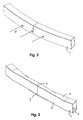
- FIG 2 shows a bumper beam model 1 of known type constructed from an aluminium alloy.
- a force F will be applied on the bumper beam 1 as indicated by the arrows. Due to the applied force, the bumper beam deforms as indicated in Figure 3.
- the impact forces leave dents 2 on the bumper beam as can be seen in Figure 3, in which cracks are likely to occur. If cracks form in a structure, the ability to absorb energy is largely reduced.
- the main functionality of a bumper beam is to absorb energy and it is therefore important to avoid the forming and propagation of cracks. There are some important considerations when modifying the properties of a bumper beam 1. If the bumper beam 1 is too easy to deform, it will not absorb enough impact energy to avoid structural damage. On the other hand, if the bumper beam 1 is too hard to deform, the stress load required to start the deformation will be too high. The bumper beam 1 will then transfer the stresses through the crash box into the vehicle body, thereby causing damage along with injury to the passengers.
- a simulation of the deformation behaviour is performed upon a model of the bumper beam 1, with given values for yield strength, wall thickness and so on, and the applied force F. This is shown in step 100 of Figure 1.
- the modelling is performed using a finite elements method implemented by software running upon a computer workstation.
- the results of the simulated deformation are analysed. This may involve determining whether the deformation behaviour meets standards required by a motoring manufacturer or regulatory authority.
- the required standards are not met and therefore at step 102 of Figure 1, the strain of the material during the deformation is used to define one or more 'regions within the structural member where the strain due to the applied force F is the greatest. These regions are the most at risk from cracking during a crash situation. The region(s) where dents or cracks are likely to occur are therefore defined and the finite element method is used to bound these regions.
- the next step is to carry out numerical modelling to determine a suitable heat treatment.
- a heat treatment is selected and modelled individually for each selected region at step 103.
- the simulated heat treatment in this case is applied using a localised heat source (analogous to laser heating) and this heat source is also allowed to move so as to traverse each region.
- Typical parameters defining the heat treatment include the travel speed, direction and the intensity distribution.
- the heat treatment parameters may be selected automatically based upon previously provided data, or alternatively, the user of the simulation model may enter the values directly.
- bumper beams are designed to have high strength properties in the region 3 (see Figure 3) suffering the direct impact.
- the regions 4,5 usually do not require high strength and it is more important to prevent crack propagation (and therefore to absorb energy) in these regions 4,5.
- FIG. 4a An example of a suitable heat treatment upon an identified region 6 is shown in Figure 4a.
- the region 6 is identified as one in which extensive deformation is normally experienced.
- a heat treatment is determined to soften the material in the region 6, the simulated heat treatment being performed using a localised and moveable heat source 8 such as provided by a laser beam.
- the direction of travel of the heat source is shown at 7 in Figure 4a.
- the region 6 is situated on the top wall 4 of the bumper beam and a corresponding region is situated on the lower wall 5 (see Figure 3).
- the heat source 8 has passed along the region 6 leaving a soft zone.
- a Gaussian distribution function is used to simulate the heat source.
- the heat source has a net heat input of 1800 W and a travel speed of 50 mm/s. 95% of the heating effect is produced within a distance of 10 mm from the centre of the source.
- a heated zone in the bumper beam wall follows the heat source 8 during the simulated heat treatment.
- the zone has a temperature gradient as indicated in Figure 4b, the maximum temperature attained being about 350°C.
- the temperatures are high, descending rapidly as the beam moves along its path.
- the result in the bumper beam wall 4 is a region with a noticeably lowered yield strength and increased ductility, forming a soft line along the region 6 on the bumper beam 1.
- Figure 4c shows the simulated difference in yield strength.
- the region 6 has a predicted yield strength of around 140 MPa while the surrounding structure has a yield strength of 260 MPa. This reduction in yield strength is accompanied by approximately a 100% increase in elongation to fracture for the alloy of the beam in this example, AA6082.
- the predicted properties of the material within the region 6 are then compared with the desired properties at step 104.
- the desired properties are either those chosen automatically or by the model user.
- a new heat treatment is determined at step 105 for the bumper beam in the state prior to heat treatment. Typically this involves using modified input values for the heat source intensity and travel speed. Steps 103, 104 and 105 may be repeated a number of times and the loop is terminated when melting of the material is avoided and the change in ductility has reached a desired value.
- the simulation process ends at step 106 as a suitable deformation and heat treatment have been identified.
- the simulation of the deformation behaviour is then performed again at step 107, using the modified material properties for the bumper beam 1. Due to the increased ductility of the material within the region 6, the deformation behaviour is improved.
- step 108 the simulations are stopped.
- a modification can be made to the above method in that the steps 100 to 102 can be performed repeatedly using different material property values for the regions selected prior to determining the heat treatment. For example, a user of the model may wish to identify regions within each simulated deformation and assess the effect of changing the material properties for those regions. This may in turn produce further regions of extensive strain.
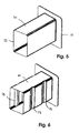
- a typical crash box 10 is shown in Figure 5, constructed from an aluminium alloy.
- An end plate 11 is welded, bolted or other-wise attached to the bumper beam.
- the front 12 of the crash box 10 is attached to the main structure of the vehicle. When a force F is applied on the bumper beam, the crash box 10 will deform and absorb part of the energy of the impact.
- Figure 7a shows a graph from a crash test upon a crash box, indicating the applied force (Y axis) necessary to attain deformation in a typical crash box of known type as a function of time (X axis).
- the first peak 14 in Figure 7a shows the force necessary for any deformation to occur in the crash box.
- the next peak 15 indicates a hardening face in the deformation pattern.
- the second peak 15 shows that parts of the crash box start deforming only at a higher level of force.
- improved safety performance results from delaying the maximum forces to later times in the impact. To improve this deformation behaviour the zones causing the second peak 15 are firstly detected and then softened.
- the regions were selected by a user, based upon experience.
- an analysis using the method described above could have been performed for the crash box 10, the position and extent of regions of high strain being calculated as a result of the deformation simulation.
- Figure 7b shows a graph equivalent to that of Figure 7a for the crash box 10'.
- the deformation of the crash box with soft zones starts at the same critical force level as the crash box without soft zones. After the deformation has started in the crash box 10', the forces applied to the crash box can be seen to be more constant through the deformation course.
- the second peak 15 which occurred in the previous example is eliminated due to the heat treatment. As indicated by the first peak in Figure 7b, soft zones are introduced through heat treatment without losing the overall energy absorbing capacity of the crash box.
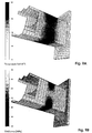
- Figure 8a shows the simulated undeformed crash box 10 having the response shown in Figure 7a.
- Figure 8b shows the simulated deformation behaviour of the crash box 10' corresponding to Figure 7b.
- Fig. 9a shows the extent of the local heat treatment upon the crash box 10'. This results in soft zones of lower yield stress being generated within the crash box 10' as indicated in Figure 9b. The material will also experience some strength recovery upon prolonged natural ageing or upon an artificial ageing heat treatment, although this is not shown in the figure.
- FIG. 10a shows a typical welded T-joint commonly seen in many structures.
- the material is generally more brittle as is well known. Due to the location of the weld 20 partly in a corner where the highest stresses will occur, cracking in the joint often becomes a problem as illustrated in Figure 10b.
- the energy absorbed by the T-joint before deformation is dependent on the force applied to the beam 21 and on the displacement of the beam 21. If the displacement is small, the energy E 1 absorbed is correspondingly small as seen on the graph of Figure 10c. This is an important factor for example in vehicle structures which are constructed to tolerate as high forces of impact as possible during collision without damaging the passengers.
- a way to solve the lack of ductility in the construction is to perform the method described in connection with Figure 1. Regions of high stress and strain in the T-joint are mapped through a simulation of the structure when it is subjected to external forces. Cracking may occur because of too low ductility in the joint and surrounding areas.
- a solution to the ductility problem is to introduce a soft zone in a region 22 in the beam 21 above the weld.
- this region 22 does not correspond to that in which the cracking or fracture is most likely to occur as the weld metal does not respond as well to heat treatments as the base material.
- a suitable heat treatment scheme is predicted through simulation.
- the beam 21 is then heat treated in accordance with the determined heat treatment so as to generate a local soft zone 22 as shown in Figure 11a. This soft zone distributes plastic deformation over a larger area and the structure thereby absorbs more deformation energy.
- This concept is schematically illustrated for the T-joint 20 containing a soft zone 22 which acts to divert high strains away from the brittle weld 20 and thus avoid early fracture of the structure.
- the beam 21 will bend in the soft zone 22, avoiding cracking of the weld 20 as shown in Figure 11B.
- a graph of the energy E 2 absorbed is schematically shown in Figure 11c for comparison with a corresponding graph for the untreated structure in Figure 10c. With the increased displacement of the beam 21, the energy absorbed during deformation is increased.
- crash components or systems comprising for example a set of crash boxes and a bumper beam are subject to strict tolerances with respect to chemical composition of the alloys and geometrical dimensions. These factors are paramount in order to meet the carefully designed behaviour of the system during a crash.
- a solution to this problem is to use the method described above as part of an inline modification method with continuous simulation and adjustment of the mechanical properties of the components during production.
- the properties of the alloy in the workpiece are determined by automatic hardness measurement or alternatively by some real-time chemical analysis.
- gauge thickness of the most critical areas are measured. This can be done optically, mechanically, with eddy currents or any other practical means.
- the resulting material response according to the parameters is simulated, thereby mapping any critical regions. If the response shows unwanted energy absorbing behaviour, a corrective step is performed by subjecting one or several areas of the part to a short thermal cycle that appropriately renders the mechanical properties in selected regions from a maximum strength condition to a softened material.
- the heating is preferably conducted by induction coil, plasma, gas flame, laser or other confined heat sources but without any melting of the material. It has previously been shown by simulation that such rapid temperature cycles may significantly change the nature of collapse and total energy absorption of a crash box.
- Such localised regions can be placed quickly within a structural member and without the use of any backing material.
- the size and effect of the region is easily adjusted by the power input and for example, induction coil design.
- the localised thermal trigger regions can be placed in almost any position and in areas that are difficult or impossible to access by traditional tooling.
- Extrusions of an aluminium alloy AA6063 for a front crash box 25 were cut into lengths and heat treated to the T6 temper condition. The flanges were machined off. The dimensions of this front crash box were about 220 mm by 92 mm by 58 mm, with a wall thickness of about 2 mm, these values being about the same as those for the crash boxes shown in Figures 8A,8B,9A,9B.
- a series of thermal triggers were then placed in various patterns across the crash box utilising an induction coil connected to a standard EDF-Elva 45 kW rectifier.
- the control parameters used were a current of 60A and a potential difference of 130V.
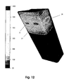
- FIG. 12 shows the peak temperature field (temperatures in degrees Celsius) for three triggers 26,27,28 respectively, after 5 seconds of heating each localised region with the experimental coil.
- a further three triggers are symmetrically positioned on the opposing hidden surfaces.
- the shading of the figures indicates the thermal gradients generated in the surface of the crash box. Similar gradients are experienced through the 2mm thickness of the material due to the high thermal conductivity. The thermal cycle experienced at each point within the crash box determines the local material properties and, as a consequence, the deformation behaviour.
- the crash box 25 as shown in Figure 12 having six triggers (three shown in the figure) placed about 20 to 30mm from the end 29 of the crash box, proved to be particularly effective in reducing the initial load peak.
- the end 29 of the crash box 25 shown in Figure 12 is orientated facing towards the front of a vehicle when the crash box is installed.
- Press tests were performed upon three of the crash boxes 25 of the type described above. Each press test was performed with an instrumented servo-hydraulic press so as to provide sampled values for force and displacement during axial deformation of the box.
- the first crash box had no trigger, the second had a thermal trigger and the third had traditional "imprints", that is regions such as those shown at 13 in Figure 6.
- the corresponding force-displacement data recorded are shown in Figure 13. It can be seen that the initial yielding peak at a displacement of about 20 mm is reduced for the crash box with thermal triggers. This demonstrates that the 6 thermal triggers acting as soft zones give a desired reduction in the force experienced at the early stage of deformation.
- the purpose of the trigger in each case is to initiate a controlled folding or buckling of the box during compression and therefore to absorb the energy of an impact. Without any trigger the initial force becomes unacceptably high, which again may lead to damage of other parts of the vehicle to which the crash box is mounted, or the passengers.
- the initial peak is reduced by about 25% in the heat treated (trigger) samples.
- the deviations between the measurements in the crash box samples are about the same for boxes with and without triggers. In each case the minimum value is shown at 30, and the maximum at 31 in Figure 14.
- the cycle time can be conservatively estimated as about 7 seconds per box. Relatively simple machinery is required to achieve this. Assuming that the crash boxes were positioned for example on a conveyor, the actual coils could preferably operate along a single axis, automatically pushing the coils towards the surface of the box. Alternatively an angular ring coil could be placed concentrically over the crash box. The optimised cycle time could actually be as low as 2-4 seconds.
- the heat treatment scheme is developed for a flexible high-intensity heat source.
- a controlled direct diode laser or possibly specially designed induction coils it is possible to facilitate fine lines, spots or intricate patterns that possess material properties substantially different from the adjacent base material.
- the method according to the present invention is not limited to heat treatments in which heat is applied as illustrated by the above examples.
- a suitable cooling treatment may be applied as part of the fabrication process, as an appropriate way of modifying the material properties of the structural members.
- a heat treatment using controlled cooling can be applied as part of a hot fabrication process.
- One of the challenges resolved by the present method is to find the sufficient amount of heating preventing the material from melting. It is a great advantage of the method according to the invention that these values are found through simulation before any full scale testing.
Landscapes
- Engineering & Computer Science (AREA)
- Mechanical Engineering (AREA)
- Chemical & Material Sciences (AREA)
- Materials Engineering (AREA)
- Crystallography & Structural Chemistry (AREA)
- Thermal Sciences (AREA)
- Physics & Mathematics (AREA)
- Metallurgy (AREA)
- Organic Chemistry (AREA)
- Heat Treatment Of Articles (AREA)
- Control Of Heat Treatment Processes (AREA)
- Waste-Gas Treatment And Other Accessory Devices For Furnaces (AREA)
- Vibration Dampers (AREA)
- Superconductors And Manufacturing Methods Therefor (AREA)
- Investigating Strength Of Materials By Application Of Mechanical Stress (AREA)
Claims (39)
- Verfahren zur Festlegung einer Wärmebehandlung, die auf ein Bauteil angewandt wird, um das Verformungsverhalten des Bauteils zu modifizieren, wenn es einer beaufschlagten Spannung unterworfen wird, wobei das Verfahren Folgendes umfasst:Simulieren des Verformungsverhaltens (100) des Bauteils, wenn es der beaufschlagten Spannung unterworfen wird;Simulieren der Wirkung mindestens einer Wärmebehandlung (103) auf zumindest einen Teil des Bauteils, um eine Wärmebehandlung festzulegen, die auf zumindest einen Teil des Bauteils anzuwenden ist, um das modifizierte Verformungsverhalten hervorzubringen;Überwachen eines erhaltenen Bauteil-Werkstücks, um Überwachungsdaten zu erzeugen, wobei die Simulation des Verformungsverhaltens unter Verwendung der Überwachungsdaten erfolgt; undAnwenden der festgelegten Wärmebehandlung(en) auf das Bauteil-Werkstück.
- Verfahren nach Anspruch 1, wobei die Simulation der Verformung unter Verwendung eines numerischen Modellverfahrens durchgeführt wird.
- Verfahren nach Anspruch 1 oder 2, wobei die Simulation der Wärmebehandlung unter Verwendung eines numerischen Modellverfahrens durchgeführt wird.
- Verfahren nach Anspruch 2 oder 3, wobei die numerische Modellbildung eine Finite-Elemente-Methode umfasst.
- Verfahren nach einem der vorangehenden Ansprüche, wobei die Wärmebehandlung mit einer lokalen Wärmequelle simuliert wird.
- Verfahren nach einem der vorangehenden Ansprüche, wobei die Wärmebehandlung mit einer beweglichen Wärmequelle simuliert wird.
- Verfahren nach einem der vorangehenden Ansprüche, wobei die Wärmebehandlung so festgelegt wird, dass die simulierte Temperatur, die in dem Bauteil erzeugt wird, unter der Schmelztemperatur für das Material liegt.
- Verfahren nach einem der vorangehenden Ansprüche, wobei jede Wärmebehandlung durch einen Parameter definiert ist und wobei eine Anzahl von Wärmebehandlungen durch Variieren des Parameters simuliert wird.
- Verfahren nach Anspruch 8, wobei der Wärmebehandlungsparameter entweder die Fortbewegungsgeschwindigkeit der Wärmequelle oder die Wärmezufuhr oder die Wärmeintensitätsverteilung oder die Maximaltemperatur der Wärmequelle beschreibt.
- Verfahren nach einem der vorangehenden Ansprüche, wobei die Wärmebehandlung automatisch festgelegt wird.
- Verfahren nach einem der vorangehenden Ansprüche, wobei das Verfahren weiterhin das Auswählen eines oder mehr Bereiche, die zu dem Bauteil gehören, in Übereinstimmung mit der simulierten Verformung umfasst.
- Verfahren nach Anspruch 11, wobei jeder Bereich in Übereinstimmung mit einer Verformungseigenschaft ausgewählt wird.
- Verfahren nach Anspruch 12, wobei die Verformungseigenschaft ausgewählt wird aus einer Duktilitäts-, Spannungs-, Dehnungs-, Elongations- oder Brucheigenschaft.
- Verfahren nach Anspruch 12 oder Anspruch 13, wobei jeder Bereich an einer Stelle in dem Bauteil in Übereinstimmung mit einem Schwellenwert bei der Verformungseigenschaft ausgewählt wird.
- Verfahren nach einem der Ansprüche 12 bis 14, das weiterhin das Zuordnen eines Zielschwellenwerts zu der Verformungseigenschaft für jeden Bereich umfasst.
- Verfahren nach Anspruch 15, weiterhin wiederholt umfassend:Simulieren der Verformung des Bauteils mit dem zugeordneten Verformungseigenschaftsschwellenwert in jedem Bereich;Vergleichen der simulierten Verformung mit einem gewünschten Verhalten; undZuordnen eines neuen Zielschwellenwerts und/oder neuer Bereiche;bis das gewünschte Verformungsverhalten simuliert ist.
- Verfahren nach Anspruch 15 oder Anspruch 16, wobei die Wärmebehandlung festgelegt wird, um ein Verformungsverhalten hervorzubringen, das den Zielschwellenwert in jedem Bereich erreicht.
- Verfahren nach Anspruch 17 bei Abhängigkeit von Anspruch 16, wobei das hervorgebrachte Verformungsverhalten das gewünschte Verformungsverhalten ist.
- Verfahren nach einem der Ansprüche 11 bis 18, wobei die Auswahl jedes Bereichs automatisch erfolgt.
- Verfahren nach einem der vorangehenden Ansprüche, welches weiterhin das Simulieren des Verformungsverhaltens des Bauteils in dem wärmebehandelten Zustand umfasst.
- Verfahren nach Anspruch 20 bei Abhängigkeit von Anspruch 11, welches weiterhin das Wiederholen des Verfahrens umfasst, um weitere Bereiche für nachfolgende Wärmebehandlung zu identifizieren.
- Verfahren nach einem der vorangehenden Ansprüche, wobei die festgelegten Wärmebehandlungen angewandt werden unter Verwendung einer lokalen regulierbaren Wärmequelle.
- Verfahren nach Anspruch 22, wobei die Wärmebehandlungen unter Verwendung eines Lasers oder von Induktionsspulen angewandt werden.
- Verfahren nach einem der vorangehenden Ansprüche, wobei die Wärmebehandlung für jeden Bereich aus einer Gruppe vorbestimmter Wärmebehandlungen für das Bauteil ausgewählt wird.
- Verfahren nach einem der vorangehenden Ansprüche, wobei das Bauteil mindestens zwei untergeordnete Strukturteile umfasst, die zusammengeschweißt sind.
- Verfahren nach einem der vorangehenden Ansprüche, wobei das Bauteil ein Fahrzeugaufprallelement ist.
- Computerprogramm, das Computerprogrammcode-Mittel umfasst, die das Verfahren nach einem der vorangehenden Ansprüche durchführen.
- Computerprogramm nach Anspruch 27, das auf einem computerlesbaren Medium enthalten ist.
- Aufprallschutzteil, das mindestens einen lokalen wärmebehandelten Bereich umfasst, wobei jeder des mindestens einen Bereichs durch die Anwendung einer Wärmebehandlung auf einen lokalen Bereich des Aufprallschutzteils erzeugt ist, die Wärmebehandlung durch das Verfahren nach einem der Ansprüche 1 bis 26 festgelegt ist, wobei jeder wärmebehandelte Bereich eingerichtet ist, um das Verformungsverhalten des Aufprallschutzteils zu modifizieren, wenn das Teil einer beaufschlagten Spannung unterworfen wird.
- Aufprallschutzteil nach Anspruch 30, wobei jeder Bereich durch die Anwendung einer Wärmebehandlung an einer Oberfläche des Teils erzeugt ist, besagte Oberfläche durch eine erste und eine zweite Achse definiert ist, wobei jeder wärmebehandelte Bereich in Bezug auf die besagte Oberfläche in einer Weise örtlich begrenzt ist, dass sich jeder Bereich entlang nur einem Teil der Oberfläche in Bezug auf jede der ersten und der zweiten Achse erstreckt.
- Aufprallschutzteil nach Anspruch 29 oder 30, wobei der wärmebehandelte Bereich in einer Weise örtlich begrenzt ist, dass, während der Anwendung der Wärmebehandlung, thermische Gradienten in dem Teil entlang jeder der ersten und der zweiten Achse gebildet werden, welche die Oberfläche während der gesamten Dauer der Wärmebehandlung definieren.
- Aufprallschutzteil nach einem der Ansprüche 29 bis 31, wobei jede der Dimensionen jedes Bereichs klein ist in Bezug auf die entsprechenden Dimensionen der Oberfläche.
- Aufprallschutzteil nach einem der Ansprüche 29 bis 32, wobei jeder Bereich auf der Oberfläche so angeordnet ist, dass er im Wesentlichen von der Grenze der Oberfläche umschlossen wird.
- Aufprallschutzteil nach einem der Ansprüche 29 bis 33, wobei das Aufprallschutzteil eine Mehrzahl separater örtlich begrenzter wärmebehandelter Bereiche umfasst.
- Aufprallschutzteil nach Anspruch 34, wobei mindestens ein wärmbehandelter Bereich auf jeder einer Mehrzahl von Oberflächen des Aufprallschutzteils vorgesehen ist.
- Aufprallschutzteil nach einem der Ansprüche 29 bis 35, wobei das Aufprallschutzteil eine Fahrzeug-Crash-Box ist.
- Aufprallschutzteil nach einem der Ansprüche 29 bis 36, wobei, für jeden Bereich, die Dicke des Teilmaterials in einer zu der Oberfläche normalen Richtung und die entsprechende Wärmebehandlung so eingerichtet sind, dass eine im Wesentlichen ähnliche Wärmebehandlung an jedem Punkt durch die Dicke des Materials in der zu der Oberfläche normalen Richtung geboten wird.
- Aufprallschutzteil nach einem der Ansprüche 29 bis 37, das aus einer Aluminiumlegierung hergestellt ist.
- Aufprallschutzteil nach einem der Ansprüche 29 bis 38, wobei das modifizierte Verformungsverhalten eine erhöhte Energieabsorption während der Verformung oder eine Verringerung der beaufschlagten Spannung umfasst, bei welcher das Aufprallschutzteil beginnt, sich plastisch zu verformen.
Applications Claiming Priority (3)
| Application Number | Priority Date | Filing Date | Title |
|---|---|---|---|
| GBGB0203059.1A GB0203059D0 (en) | 2002-02-08 | 2002-02-08 | Method of determining a heat treatment |
| GB0203059 | 2002-02-08 | ||
| PCT/NO2003/000048 WO2003066383A1 (en) | 2002-02-08 | 2003-02-07 | Method of determining a heat treatment and member so treated |
Publications (2)
| Publication Number | Publication Date |
|---|---|
| EP1472115A1 EP1472115A1 (de) | 2004-11-03 |
| EP1472115B1 true EP1472115B1 (de) | 2006-05-24 |
Family
ID=9930742
Family Applications (1)
| Application Number | Title | Priority Date | Filing Date |
|---|---|---|---|
| EP03737522A Expired - Lifetime EP1472115B1 (de) | 2002-02-08 | 2003-02-07 | Verfahren zur bestimmung einer wärmebehandlung und so behandeltes glied |
Country Status (7)
| Country | Link |
|---|---|
| US (1) | US7494553B2 (de) |
| EP (1) | EP1472115B1 (de) |
| AT (1) | ATE327128T1 (de) |
| AU (1) | AU2003244393A1 (de) |
| DE (1) | DE60305444T2 (de) |
| GB (1) | GB0203059D0 (de) |
| WO (1) | WO2003066383A1 (de) |
Families Citing this family (9)
| Publication number | Priority date | Publication date | Assignee | Title |
|---|---|---|---|---|
| DE10339949A1 (de) * | 2003-08-29 | 2005-03-31 | Euromotive Ges.M.B.H. & Co. Kg | Stoßfänger für ein Kraftfahrzeug |
| JP4118263B2 (ja) * | 2004-07-15 | 2008-07-16 | 本田技研工業株式会社 | 自動車用衝撃吸収部材 |
| US7412300B2 (en) * | 2005-07-27 | 2008-08-12 | General Electric Company | Thermal forming |
| DE102005057429B4 (de) * | 2005-11-30 | 2009-06-25 | Benteler Automobiltechnik Gmbh | Crashbox |
| CN102117360B (zh) * | 2010-12-31 | 2016-02-24 | 长城汽车股份有限公司 | 快速匹配车辆正碰有限元模型的方法 |
| JP6550641B2 (ja) * | 2015-02-19 | 2019-07-31 | 本田技研工業株式会社 | 車両の前部車体構造 |
| CN107657112B (zh) * | 2017-09-25 | 2020-09-04 | 中国铁路总公司 | 一种轨道列车多级能量吸收的耐冲击优化设计方法 |
| CN115418453B (zh) * | 2022-08-30 | 2023-11-24 | 湖南大学 | 用于吸能结构局部均匀强化与弱化的处理系统及方法 |
| DE102023110007A1 (de) | 2023-04-20 | 2024-10-24 | Audi Aktiengesellschaft | Verfahren zur Herstellung einer Karosserie oder eines Karosserieteils eines Kraftfahrzeugs |
Family Cites Families (11)
| Publication number | Priority date | Publication date | Assignee | Title |
|---|---|---|---|---|
| DE2429496A1 (de) | 1974-06-20 | 1976-01-08 | Volkswagenwerk Ag | Traeger, insbesondere laengstraeger fuer fahrzeuge |
| NO168880C (no) | 1990-03-06 | 1992-04-15 | Norsk Hydro As | Energiabsorberende konstruksjon for opptak av anslagsenergi samt fremgangsmaate ved fremstilling av denne |
| CH687816A5 (de) | 1994-10-26 | 1997-02-28 | Alusuisse Lonza Services Ag | Sicherheitslenksaeule. |
| NO952840D0 (no) * | 1995-07-17 | 1995-07-17 | Norsk Hydro As | Stötfangersystem |
| JPH10128817A (ja) | 1996-10-28 | 1998-05-19 | Matsushita Electric Works Ltd | 成形品の変形シミュレーション方法及び最適モデル決定方法 |
| US6353768B1 (en) * | 1998-02-02 | 2002-03-05 | General Electric Company | Method and apparatus for designing a manufacturing process for sheet metal parts |
| EP0978444A3 (de) * | 1998-08-04 | 2004-11-10 | Volkswagen Aktiengesellschaft | Verfahren zur Ermittlung der Verformungen und Spannungen einer aus Teilstrukturen bestehenden Gesamtstruktur |
| US6212486B1 (en) | 1998-09-17 | 2001-04-03 | Ford Global Technologies, Inc. | Method of identifying critical elements in fatigue analysis with von mises stress bounding and filtering modal displacement history using dynamic windowing |
| JP2001297955A (ja) | 2000-04-14 | 2001-10-26 | Toshiba Corp | シミュレーション方法、シミュレータ及びシミュレーションプログラムを記録した記録媒体 |
| GB0119023D0 (en) * | 2001-08-03 | 2001-09-26 | Norsk Hydro As | Method and apparatus for distorting a workpiece |
| JP4532143B2 (ja) * | 2004-03-17 | 2010-08-25 | プレス工業株式会社 | 板材成形シミュレーション及びプレス成形方法 |
-
2002
- 2002-02-08 GB GBGB0203059.1A patent/GB0203059D0/en not_active Ceased
-
2003
- 2003-02-07 EP EP03737522A patent/EP1472115B1/de not_active Expired - Lifetime
- 2003-02-07 WO PCT/NO2003/000048 patent/WO2003066383A1/en not_active Ceased
- 2003-02-07 AU AU2003244393A patent/AU2003244393A1/en not_active Abandoned
- 2003-02-07 US US10/502,395 patent/US7494553B2/en not_active Expired - Fee Related
- 2003-02-07 DE DE60305444T patent/DE60305444T2/de not_active Expired - Lifetime
- 2003-02-07 AT AT03737522T patent/ATE327128T1/de not_active IP Right Cessation
Also Published As
| Publication number | Publication date |
|---|---|
| EP1472115A1 (de) | 2004-11-03 |
| ATE327128T1 (de) | 2006-06-15 |
| AU2003244393A1 (en) | 2003-09-02 |
| WO2003066383A1 (en) | 2003-08-14 |
| US7494553B2 (en) | 2009-02-24 |
| DE60305444T2 (de) | 2007-05-03 |
| GB0203059D0 (en) | 2002-03-27 |
| DE60305444D1 (de) | 2006-06-29 |
| US20050145305A1 (en) | 2005-07-07 |
Similar Documents
| Publication | Publication Date | Title |
|---|---|---|
| Omer et al. | Testing of a hot stamped axial crush member with tailored properties–experiments and models | |
| EP1472115B1 (de) | Verfahren zur bestimmung einer wärmebehandlung und so behandeltes glied | |
| US6227023B1 (en) | Hybrid matched tool-hydraulic forming methods | |
| US6050121A (en) | Hybrid methods of metal forming using electromagnetic forming | |
| Chantzis et al. | Design for additive manufacturing (DfAM) of hot stamping dies with improved cooling performance under cyclic loading conditions | |
| US6047582A (en) | Hybrid matched tool-electromagnetic forming apparatus incorporating electromagnetic actuator | |
| Cao et al. | Next generation stamping dies—controllability and flexibility | |
| Safari et al. | Experimental and numerical investigation of laser bending of tailor machined blanks | |
| US6050120A (en) | Hybrid matched tool-electromagnetic forming apparatus | |
| Jerniti et al. | Single track laser surface hardening model for AISI 4340 steel using the finite element method | |
| US6085562A (en) | Hybrid matched tool forming methods | |
| Wen et al. | Rolling to control residual stress and distortion in friction stir welds | |
| Brust et al. | Mitigating welding residual stress and distortion | |
| WO2019086381A1 (en) | Method and apparatus for post weld heat treatment of aluminium alloy components, and a welded aluminium component treated according to the method | |
| US6128935A (en) | Hybrid matched tool-electromagnetic forming apparatus incorporating electromagnetic actuator | |
| Güler et al. | Comparison of hot and cold stamping simulation of Usibor 1500 prototype model | |
| Dahan et al. | Formability investigations for the hot stamping process | |
| Lanzerath et al. | Lightweight potential of ultra high strength steel tubular body structures | |
| Liu et al. | Hot stamping of AA6082 tailor welded blanks: experiment and FE simulation | |
| Ruszkiewicz et al. | Incrementally formed stiffeners effect on the reduction of springback in 2024-T3 aluminum after single point incremental forming | |
| Das et al. | Residual stress and distortion | |
| Kumar et al. | Thermo-Mechanical Behavior of Multi-Layer Deposition for Wire Arc Additive Manufacturing of Structural Steel: Wire Arc Additive Manufacturing | |
| Bjørneklett et al. | Material design and thermally induced triggers in crash management | |
| Lee | On the Development of Fold Initiator Patterns to Promote Progressive Folding of Hot Stamped Ultra-High Strength Axial Crush Structures | |
| Dry et al. | Methods of assessing influence of weld properties on formability of laser welded tailored blanks |
Legal Events
| Date | Code | Title | Description |
|---|---|---|---|
| PUAI | Public reference made under article 153(3) epc to a published international application that has entered the european phase |
Free format text: ORIGINAL CODE: 0009012 |
|
| 17P | Request for examination filed |
Effective date: 20040825 |
|
| AK | Designated contracting states |
Kind code of ref document: A1 Designated state(s): AT BE BG CH CY CZ DE DK EE ES FI FR GB GR HU IE IT LI LU MC NL PT SE SI SK TR |
|
| AX | Request for extension of the european patent |
Extension state: AL LT LV MK RO |
|
| 17Q | First examination report despatched |
Effective date: 20050105 |
|
| GRAP | Despatch of communication of intention to grant a patent |
Free format text: ORIGINAL CODE: EPIDOSNIGR1 |
|
| RIN1 | Information on inventor provided before grant (corrected) |
Inventor name: BJORNEKLETT, BORGE Inventor name: STJERN, TOR, ARNE Inventor name: MYHR, OLE, RUNAR |
|
| GRAS | Grant fee paid |
Free format text: ORIGINAL CODE: EPIDOSNIGR3 |
|
| GRAA | (expected) grant |
Free format text: ORIGINAL CODE: 0009210 |
|
| AK | Designated contracting states |
Kind code of ref document: B1 Designated state(s): AT BE BG CH CY CZ DE DK EE ES FI FR GB GR HU IE IT LI LU MC NL PT SE SI SK TR |
|
| PG25 | Lapsed in a contracting state [announced via postgrant information from national office to epo] |
Ref country code: IT Free format text: LAPSE BECAUSE OF FAILURE TO SUBMIT A TRANSLATION OF THE DESCRIPTION OR TO PAY THE FEE WITHIN THE PRESCRIBED TIME-LIMIT;WARNING: LAPSES OF ITALIAN PATENTS WITH EFFECTIVE DATE BEFORE 2007 MAY HAVE OCCURRED AT ANY TIME BEFORE 2007. THE CORRECT EFFECTIVE DATE MAY BE DIFFERENT FROM THE ONE RECORDED. Effective date: 20060524 Ref country code: CZ Free format text: LAPSE BECAUSE OF FAILURE TO SUBMIT A TRANSLATION OF THE DESCRIPTION OR TO PAY THE FEE WITHIN THE PRESCRIBED TIME-LIMIT Effective date: 20060524 Ref country code: FI Free format text: LAPSE BECAUSE OF FAILURE TO SUBMIT A TRANSLATION OF THE DESCRIPTION OR TO PAY THE FEE WITHIN THE PRESCRIBED TIME-LIMIT Effective date: 20060524 Ref country code: SK Free format text: LAPSE BECAUSE OF FAILURE TO SUBMIT A TRANSLATION OF THE DESCRIPTION OR TO PAY THE FEE WITHIN THE PRESCRIBED TIME-LIMIT Effective date: 20060524 Ref country code: LI Free format text: LAPSE BECAUSE OF FAILURE TO SUBMIT A TRANSLATION OF THE DESCRIPTION OR TO PAY THE FEE WITHIN THE PRESCRIBED TIME-LIMIT Effective date: 20060524 Ref country code: NL Free format text: LAPSE BECAUSE OF FAILURE TO SUBMIT A TRANSLATION OF THE DESCRIPTION OR TO PAY THE FEE WITHIN THE PRESCRIBED TIME-LIMIT Effective date: 20060524 Ref country code: BE Free format text: LAPSE BECAUSE OF FAILURE TO SUBMIT A TRANSLATION OF THE DESCRIPTION OR TO PAY THE FEE WITHIN THE PRESCRIBED TIME-LIMIT Effective date: 20060524 Ref country code: CH Free format text: LAPSE BECAUSE OF FAILURE TO SUBMIT A TRANSLATION OF THE DESCRIPTION OR TO PAY THE FEE WITHIN THE PRESCRIBED TIME-LIMIT Effective date: 20060524 Ref country code: AT Free format text: LAPSE BECAUSE OF FAILURE TO SUBMIT A TRANSLATION OF THE DESCRIPTION OR TO PAY THE FEE WITHIN THE PRESCRIBED TIME-LIMIT Effective date: 20060524 Ref country code: SI Free format text: LAPSE BECAUSE OF FAILURE TO SUBMIT A TRANSLATION OF THE DESCRIPTION OR TO PAY THE FEE WITHIN THE PRESCRIBED TIME-LIMIT Effective date: 20060524 |
|
| REG | Reference to a national code |
Ref country code: CH Ref legal event code: EP |
|
| REG | Reference to a national code |
Ref country code: IE Ref legal event code: FG4D |
|
| REF | Corresponds to: |
Ref document number: 60305444 Country of ref document: DE Date of ref document: 20060629 Kind code of ref document: P |
|
| PG25 | Lapsed in a contracting state [announced via postgrant information from national office to epo] |
Ref country code: DK Free format text: LAPSE BECAUSE OF FAILURE TO SUBMIT A TRANSLATION OF THE DESCRIPTION OR TO PAY THE FEE WITHIN THE PRESCRIBED TIME-LIMIT Effective date: 20060824 Ref country code: SE Free format text: LAPSE BECAUSE OF FAILURE TO SUBMIT A TRANSLATION OF THE DESCRIPTION OR TO PAY THE FEE WITHIN THE PRESCRIBED TIME-LIMIT Effective date: 20060824 |
|
| PG25 | Lapsed in a contracting state [announced via postgrant information from national office to epo] |
Ref country code: ES Free format text: LAPSE BECAUSE OF FAILURE TO SUBMIT A TRANSLATION OF THE DESCRIPTION OR TO PAY THE FEE WITHIN THE PRESCRIBED TIME-LIMIT Effective date: 20060904 |
|
| ET | Fr: translation filed | ||
| PG25 | Lapsed in a contracting state [announced via postgrant information from national office to epo] |
Ref country code: PT Free format text: LAPSE BECAUSE OF FAILURE TO SUBMIT A TRANSLATION OF THE DESCRIPTION OR TO PAY THE FEE WITHIN THE PRESCRIBED TIME-LIMIT Effective date: 20061024 |
|
| NLV1 | Nl: lapsed or annulled due to failure to fulfill the requirements of art. 29p and 29m of the patents act | ||
| REG | Reference to a national code |
Ref country code: CH Ref legal event code: PL |
|
| PG25 | Lapsed in a contracting state [announced via postgrant information from national office to epo] |
Ref country code: MC Free format text: LAPSE BECAUSE OF NON-PAYMENT OF DUE FEES Effective date: 20070228 |
|
| PLBE | No opposition filed within time limit |
Free format text: ORIGINAL CODE: 0009261 |
|
| STAA | Information on the status of an ep patent application or granted ep patent |
Free format text: STATUS: NO OPPOSITION FILED WITHIN TIME LIMIT |
|
| 26N | No opposition filed |
Effective date: 20070227 |
|
| PG25 | Lapsed in a contracting state [announced via postgrant information from national office to epo] |
Ref country code: IE Free format text: LAPSE BECAUSE OF NON-PAYMENT OF DUE FEES Effective date: 20070207 |
|
| PG25 | Lapsed in a contracting state [announced via postgrant information from national office to epo] |
Ref country code: GR Free format text: LAPSE BECAUSE OF FAILURE TO SUBMIT A TRANSLATION OF THE DESCRIPTION OR TO PAY THE FEE WITHIN THE PRESCRIBED TIME-LIMIT Effective date: 20060825 |
|
| PGFP | Annual fee paid to national office [announced via postgrant information from national office to epo] |
Ref country code: GB Payment date: 20080206 Year of fee payment: 6 |
|
| PG25 | Lapsed in a contracting state [announced via postgrant information from national office to epo] |
Ref country code: BG Free format text: LAPSE BECAUSE OF FAILURE TO SUBMIT A TRANSLATION OF THE DESCRIPTION OR TO PAY THE FEE WITHIN THE PRESCRIBED TIME-LIMIT Effective date: 20060824 |
|
| PG25 | Lapsed in a contracting state [announced via postgrant information from national office to epo] |
Ref country code: EE Free format text: LAPSE BECAUSE OF FAILURE TO SUBMIT A TRANSLATION OF THE DESCRIPTION OR TO PAY THE FEE WITHIN THE PRESCRIBED TIME-LIMIT Effective date: 20060524 |
|
| PG25 | Lapsed in a contracting state [announced via postgrant information from national office to epo] |
Ref country code: CY Free format text: LAPSE BECAUSE OF FAILURE TO SUBMIT A TRANSLATION OF THE DESCRIPTION OR TO PAY THE FEE WITHIN THE PRESCRIBED TIME-LIMIT Effective date: 20060524 Ref country code: LU Free format text: LAPSE BECAUSE OF NON-PAYMENT OF DUE FEES Effective date: 20070207 |
|
| PG25 | Lapsed in a contracting state [announced via postgrant information from national office to epo] |
Ref country code: HU Free format text: LAPSE BECAUSE OF FAILURE TO SUBMIT A TRANSLATION OF THE DESCRIPTION OR TO PAY THE FEE WITHIN THE PRESCRIBED TIME-LIMIT Effective date: 20061125 Ref country code: TR Free format text: LAPSE BECAUSE OF FAILURE TO SUBMIT A TRANSLATION OF THE DESCRIPTION OR TO PAY THE FEE WITHIN THE PRESCRIBED TIME-LIMIT Effective date: 20060524 |
|
| GBPC | Gb: european patent ceased through non-payment of renewal fee |
Effective date: 20090207 |
|
| PG25 | Lapsed in a contracting state [announced via postgrant information from national office to epo] |
Ref country code: GB Free format text: LAPSE BECAUSE OF NON-PAYMENT OF DUE FEES Effective date: 20090207 |
|
| REG | Reference to a national code |
Ref country code: FR Ref legal event code: TP |
|
| PGFP | Annual fee paid to national office [announced via postgrant information from national office to epo] |
Ref country code: DE Payment date: 20130226 Year of fee payment: 11 Ref country code: FR Payment date: 20130301 Year of fee payment: 11 |
|
| REG | Reference to a national code |
Ref country code: DE Ref legal event code: R119 Ref document number: 60305444 Country of ref document: DE |
|
| REG | Reference to a national code |
Ref country code: FR Ref legal event code: ST Effective date: 20141031 |
|
| REG | Reference to a national code |
Ref country code: DE Ref legal event code: R119 Ref document number: 60305444 Country of ref document: DE Effective date: 20140902 |
|
| PG25 | Lapsed in a contracting state [announced via postgrant information from national office to epo] |
Ref country code: FR Free format text: LAPSE BECAUSE OF NON-PAYMENT OF DUE FEES Effective date: 20140228 Ref country code: DE Free format text: LAPSE BECAUSE OF NON-PAYMENT OF DUE FEES Effective date: 20140902 |