EP1472693B1 - Procede et unite pour soustraire un bruit de quantification d'un signal mic - Google Patents
Procede et unite pour soustraire un bruit de quantification d'un signal mic Download PDFInfo
- Publication number
- EP1472693B1 EP1472693B1 EP02790650A EP02790650A EP1472693B1 EP 1472693 B1 EP1472693 B1 EP 1472693B1 EP 02790650 A EP02790650 A EP 02790650A EP 02790650 A EP02790650 A EP 02790650A EP 1472693 B1 EP1472693 B1 EP 1472693B1
- Authority
- EP
- European Patent Office
- Prior art keywords
- mrow
- signal
- quantization
- pcm
- pcm signal
- Prior art date
- Legal status (The legal status is an assumption and is not a legal conclusion. Google has not performed a legal analysis and makes no representation as to the accuracy of the status listed.)
- Expired - Lifetime
Links
- 238000013139 quantization Methods 0.000 title claims abstract description 112
- 238000000034 method Methods 0.000 title claims abstract description 30
- 238000001228 spectrum Methods 0.000 claims description 33
- 230000009466 transformation Effects 0.000 claims description 3
- 230000001131 transforming effect Effects 0.000 claims description 2
- 230000007704 transition Effects 0.000 claims description 2
- 238000011156 evaluation Methods 0.000 claims 2
- 238000009827 uniform distribution Methods 0.000 claims 2
- 238000004364 calculation method Methods 0.000 description 3
- 230000003044 adaptive effect Effects 0.000 description 2
- 239000000654 additive Substances 0.000 description 1
- 230000000996 additive effect Effects 0.000 description 1
- 230000006835 compression Effects 0.000 description 1
- 238000007906 compression Methods 0.000 description 1
- 230000003247 decreasing effect Effects 0.000 description 1
- 230000000694 effects Effects 0.000 description 1
- 238000012986 modification Methods 0.000 description 1
- 230000004048 modification Effects 0.000 description 1
- 230000005236 sound signal Effects 0.000 description 1
- 238000011410 subtraction method Methods 0.000 description 1
- 230000001629 suppression Effects 0.000 description 1
Images


Classifications
-
- G—PHYSICS
- G10—MUSICAL INSTRUMENTS; ACOUSTICS
- G10L—SPEECH ANALYSIS TECHNIQUES OR SPEECH SYNTHESIS; SPEECH RECOGNITION; SPEECH OR VOICE PROCESSING TECHNIQUES; SPEECH OR AUDIO CODING OR DECODING
- G10L21/00—Speech or voice signal processing techniques to produce another audible or non-audible signal, e.g. visual or tactile, in order to modify its quality or its intelligibility
- G10L21/02—Speech enhancement, e.g. noise reduction or echo cancellation
- G10L21/0208—Noise filtering
-
- G—PHYSICS
- G10—MUSICAL INSTRUMENTS; ACOUSTICS
- G10L—SPEECH ANALYSIS TECHNIQUES OR SPEECH SYNTHESIS; SPEECH RECOGNITION; SPEECH OR VOICE PROCESSING TECHNIQUES; SPEECH OR AUDIO CODING OR DECODING
- G10L19/00—Speech or audio signals analysis-synthesis techniques for redundancy reduction, e.g. in vocoders; Coding or decoding of speech or audio signals, using source filter models or psychoacoustic analysis
- G10L19/02—Speech or audio signals analysis-synthesis techniques for redundancy reduction, e.g. in vocoders; Coding or decoding of speech or audio signals, using source filter models or psychoacoustic analysis using spectral analysis, e.g. transform vocoders or subband vocoders
- G10L19/032—Quantisation or dequantisation of spectral components
-
- G—PHYSICS
- G11—INFORMATION STORAGE
- G11B—INFORMATION STORAGE BASED ON RELATIVE MOVEMENT BETWEEN RECORD CARRIER AND TRANSDUCER
- G11B20/00—Signal processing not specific to the method of recording or reproducing; Circuits therefor
- G11B20/10—Digital recording or reproducing
-
- H—ELECTRICITY
- H03—ELECTRONIC CIRCUITRY
- H03M—CODING; DECODING; CODE CONVERSION IN GENERAL
- H03M1/00—Analogue/digital conversion; Digital/analogue conversion
- H03M1/06—Continuously compensating for, or preventing, undesired influence of physical parameters
- H03M1/08—Continuously compensating for, or preventing, undesired influence of physical parameters of noise
- H03M1/0854—Continuously compensating for, or preventing, undesired influence of physical parameters of noise of quantisation noise
-
- H—ELECTRICITY
- H04—ELECTRIC COMMUNICATION TECHNIQUE
- H04B—TRANSMISSION
- H04B14/00—Transmission systems not characterised by the medium used for transmission
- H04B14/02—Transmission systems not characterised by the medium used for transmission characterised by the use of pulse modulation
- H04B14/04—Transmission systems not characterised by the medium used for transmission characterised by the use of pulse modulation using pulse code modulation
- H04B14/046—Systems or methods for reducing noise or bandwidth
- H04B14/048—Non linear compression or expansion
-
- H—ELECTRICITY
- H04—ELECTRIC COMMUNICATION TECHNIQUE
- H04N—PICTORIAL COMMUNICATION, e.g. TELEVISION
- H04N5/00—Details of television systems
- H04N5/76—Television signal recording
- H04N5/91—Television signal processing therefor
- H04N5/92—Transformation of the television signal for recording, e.g. modulation, frequency changing; Inverse transformation for playback
- H04N5/926—Transformation of the television signal for recording, e.g. modulation, frequency changing; Inverse transformation for playback by pulse code modulation
Definitions
- the invention relates to a method and a unit for subtracting quantization noise from a PCM signal.
- PCM Pulse code modulation
- Linear PCM uses evenly distributed quantization levels whereas the logarithmic PCM uses a distribution where small-signal amplitudes are quantized using more closely spaced levels than large-signal amplitudes.
- An example to linear PCM is the CD-audio, which uses 16 bits to represent uniformly distributed signal levels.
- Fig. 5 illustrates the quantization of a linear coded PCM signal amplitudes (curve (a)) and of two logarithmically coded PCM signal amplitudes (curve (b) and (c)).
- Curve b illustrates the quantization of ⁇ -law coded PCM signal amplitudes, wherein the ⁇ -law has an input-output magnitude characteristic of the form:
- log ( 1 + ⁇
- curve c) illustrates the quantization of A-law coded PCM signal amplitudes, wherein the A-law has an input-output magnitude characteristic of the form:
- 1 + log A
- the prior art ⁇ -law and A-law coders are standardized by the ComInstituttatif International de Telecommunicationfonique et Telecommunicationgraphique CCITT as the G.711 64kbit/s PCM.
- the quantizer characteristics of the G.711 are disclosed in: N.S. Jayant and P. Noll, "Digital Coding of Waveforms", Englewood Cliffs NJ: Prentice-Hall, 1984.
- the quantization error can be interpreted as undesired additive noise decreasing the quality of the original sample values s[n].
- the window-function may be chosen arbitrarily.
- the claimed formula requires the minimum quantization level S* min [n] as well as the maximum quantization level S* max [n] of the sample values s*[n] of the PCM signal.
- the minimum quantization level S* min [n] as well as the maximum quantization level S* max [n] are known from the quantization method applied for generating the PCM signal.
- the noise subtraction is based on a background noise subtracting method and system as described in the non-prepublished European Patent application having the application number EP 01201304.1 of the same applicant.
- the application of said system is described later as preferred embodiment.
- the claimed unit and method are applied at the decoder side, i.e. just before the PCM signal is decoded again. However, nevertheless it might also be applied at the encoder side.
- Fig. 1 shows a quantization noise subtracting unit 100-700 for subtracting quantization noise from an input linearly or logarithmically coded PCM signal.
- the number of samples per window is twice the number of samples per frame.
- the frame size is typically 2ms.
- said quantization levels S* min [n], S* max [n] are assumed to be known.
- these quantization levels S* min [n], S* max [n] are not assumed to be known, e.g. because the original signals might have been quantized with different quantizers and there may have been extra scalings applied on the samples before or after coding. In these cases the quantization levels have to be predicted.
- the entire original signal hereinafter also referred to as waveform
- waveform is scanned to receive the sample values s*[n] of the quantized waveform.
- a check is made, if all possible representation levels i predefined due the quantization method applied to the waveform are represented (used) by at least one said sample values s*[n].
- u[i] 1 (if there is at least one sample value of the whole waveform corresponding to the current representation level i) or 0 (if there is no sample value of the whole waveform corresponding to the current representation level i).
- Fig. 3 shows a detailed illustration of said background noise subtracting unit 200 which is embodied to subtract the quantization noise from a PCM signal in the frequency domain. It comprises a magnitude forming unit 210 for forming the magnitude
- of the spectrum S*[k] of the PCM signal, a signal-to-noise ratio calculating unit 220 for calculating the signal-to-noise ratio of the PCM signal according to the formula: SNR [ k ]
- Said signal-to-noise ratio SNR[k] is input into a filter update unit 230 for calculating a filter magnitude F[k] according to a predefined filter algorithm based on at least one filter update parameter.
- Said filter magnitude F[k] is input into a calculation unit 240 for calculating an output spectrum S b [k] by multiplying both the real part R ⁇ S*[k] ⁇ and the imaginary part I ⁇ S*[k] ⁇ of the spectrum S*[k] with said filter magnitude F ⁇ k ⁇ .
- the filter update parameter and thus also the filter magnitude F[k] are preferably adjusted such that output spectrum S b [k] is at least substantially free of quantization noise.
- the quantization noise subtracting unit further comprises several units for computing the spectrum S*[k] of the PCM signal to be input into said background noise subtracting unit 200 and for transforming the spectrum S b [k] output by said unit 200 back into a time domain signal. These units are described in the following paragraphs.
- the quantization noise subtracting unit further comprises a first window block 300 for generating a weighted PCM signal s* w [n] by weighting the frames of the input PCM signal with a first window w1 [n].
- Said weighted PCM signal s* w [n] is input into a spectrum computing unit 400 for computing the spectrum S*[k] from said weighted signal.
- the spectrum is computed by using the Fast Fourier Transformation algorithm.
- the spectrum S*[k] is than input into the background noise subtracting unit 200 and processed therein as described above by referring to Fig. 3.
- the spectrum S b [k] output by said background subtracting unit 200 is input into a re-transforming unit 500 for being transformed back into a signal s b [n] in the time domain.
- the re-transformation is done by using the inverse FFT.
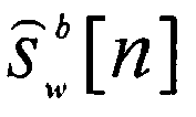
- the quantization noise subtracting unit may further comprise a second window block 600 for generating a weighted output signal s b w [n] by weighting the signal s b [n] received after the transformation with a second window W2[n] and an overlap and add unit 700 for individually calculating a final output signal S ⁇ w b [ n ] for each frame of the PCM-signal from said weighted output signal s b w [n] such that the transition between two successive output frames is smoothed.
- the first and the second window W1 and W2 are preferably identical. They are independent of the window-function w[n] used for calculating the quantization level Bq. However, it is preferred to use the same function for w[n] as for W1.
- the provision of the overlap and add unit 700 only improves the quality of the output signal but it is not absolutely necessary for carrying out the quantization noise subtraction; consequently, it might be left out.
- Fig. 4 shows an example illustrating the good signal quality achieved when applying the claimed method to a ⁇ -law coded speech signal.
- Fig. 4.1 shows the spectrum of a clean, i.e. free of quantization noise, male voice recording with the utterance: "Any dictionary will give at least twenty different definitions for it".
- Fig. 4.2 shows the ⁇ -law coded version of the spectrum shown in Fig. 4.1. From that Fig. 4.2 it can be seen that said ⁇ -law coding causes quantization noise added to the clean spectrum of Fig. 4.1.
- the quantization noise is represented by the grey-shaded areas 410; the corresponding areas in Fig. 4.1 are clean.
- Fig. 4.3 shows the spectrum from Fig. 4.2 after the quantization noise subtracting method according to the invention has been applied.
- Fig. 4.4 shows the usage array u[i] as generated by the method according to the present invention for reducing quantization noise from the spectrum shown in Fig. 4.2.
Landscapes
- Engineering & Computer Science (AREA)
- Signal Processing (AREA)
- Physics & Mathematics (AREA)
- Multimedia (AREA)
- Acoustics & Sound (AREA)
- Health & Medical Sciences (AREA)
- Audiology, Speech & Language Pathology (AREA)
- Human Computer Interaction (AREA)
- Computational Linguistics (AREA)
- Quality & Reliability (AREA)
- Spectroscopy & Molecular Physics (AREA)
- Theoretical Computer Science (AREA)
- Nonlinear Science (AREA)
- Computer Networks & Wireless Communication (AREA)
- Compression, Expansion, Code Conversion, And Decoders (AREA)
- Transmission Systems Not Characterized By The Medium Used For Transmission (AREA)
- Mobile Radio Communication Systems (AREA)
Claims (12)
- Procédé de soustraction de bruit de quantification d'un signal par impulsions codées MIC modulé segmenté en trames, comprenant les étapes de :- calcul, pour chaque trame dudit signal MIC, d'un niveau de quantification constant Bq, et- soustraction du bruit de quantification tel qu'il est représenté par ledit niveau de quantification Bq dudit signal MIC,caractérisé en ce que Bq est déterminé par une valeur de racine quadratique moyenne de l'erreur de quantification ayant pour base une différence entre un niveau de quantification minimum S*min[n] et un niveau de quantification maximum S*max[n] des valeurs échantillons s*[n] dudit signal MIC dans une fenêtre d'évaluation w[n] et ayant pour base une distribution supposée uniforme des valeurs échantillons dans un intervalle entre le niveau de quantification minimum et le niveau de quantification maximum, dans lequel :n : indique un échantillon spécifique du signal MIC ;S*min[n] : représente le niveau de quantification minimum pour une valeur échantillon spécifique s*[n] dudit signal MIC;S*max[n] : représente le niveau de quantification maximum pour la valeur échantillon spécifique s*[n] du signal MIC ;w[n] : représente une fonction de fenêtre.
- Procédé selon la revendication 1, dans lequel Bq est déterminé conformément à l'équation suivante :
 W : représente le nombre d'échantillons par fenêtre.
 - Procédé selon la revendication 1 ou 2, caractérisé en ce que le niveau de quantification minimum S*min ainsi que le niveau de quantification maximum S*max sont connus.
- Procédé selon la revendication 1 ou 2, caractérisé en ce que le niveau de quantification minimum S*min et le niveau de quantification maximum S*max sont prédits selon les équations suivantes :

 i : représente l'un d'une pluralité de niveaux de représentation possibles prédéfinis du fait du procédé de quantification MIC spécifique appliqué à un signal original ;i[n] : représente le niveau de représentation prédéfini qui correspond à la valeur échantillon s*[n] pour un n spécifique ;imin[n] : représente le niveau de représentation qui - en partant de i[n] - est le niveau de représentation non nul le plus petit suivant pour lequel u[n]= 1 ;imax[n] : représente le niveau de représentation qui - en partant de i[n] - est le niveau de représentation non nul le plus grand suivant pour lequel u[n]=1 ;le tableau d'utilisation u[i] étant défini ci-après :
 L : représente le nombre d'échantillons du signal MIC complet ; etN : représente le nombre de bits utilisés pour quantifier une valeur échantillon originale en utilisant le signal MIC pour générer les valeurs échantillons MIC s*[n].
 - Procédé selon la revendication 1 ou 2, caractérisé en ce que la soustraction du bruit de quantification représenté par ledit niveau de quantification Bq du signal MIC est effectuée dans le domaine fréquentiel selon les étapes suivantes :- calcul du spectre S*[k] du signal MIC s*[n] et formation de son amplitude |S*[k]|;- calcul d'un rapport signal à bruit RSB[k] dudit spectre S*[k] selon :
 - calcul à partir dudit rapport signal à bruit RSB[k], d'une amplitude de filtre F[k] selon un algorithme de filtrage prédéfini ayant pour base au moins un paramètre de mise à jour de filtre ;- calcul d'un spectre de sortie Sb[k] au moins sensiblement exempt dudit bruit de quantification en multipliant à la fois la partie réelle R{S*[k]} et la partie imaginaire I{S*[k]} du spectre S*[k] avec ladite amplitude de filtre F{k}; et- retransformation du spectre de sortie Sb[k] en un signal sb[n] dans le domaine temporel.
 - Procédé selon la revendication 5, caractérisé en ce que le paramètre de mise à jour de filtre et par conséquent, l'amplitude du filtre F[k], sont ajustés de façon à ce que le bruit de quantification dans le spectre de sortie Sb[k] restant soit aussi faible que possible.
- Procédé selon la revendication 5, caractérisé en ce qu'il comprend en outre les étapes de :- pondération des trames du signal MIC d'entrée par une première fenêtre w1 [n] et calcul du spectre S*[k] à partir dudit signal pondéré ;- génération d'un signal de sortie pondéré sb w[n] en pondérant le signal sb[n] reçu après la retransformation avec une deuxième fenêtre W2[n]; et- calcul d'un signal de sortie final
- Procédé selon la revendication 5, caractérisé en ce que :le calcul du spectre S*[k] du signal MIC est effectué en utilisant une Transformation de Fourier Rapide FFT ; etla retransformation du spectre de sortie Sb[k] back en un signal dans le domaine temporal sb[n] est effectué en utilisant une FFT inverse.
- Procédé selon la revendication 7, caractérisé en ce que les première et deuxième fenêtres w 1 et w2 sont identiques.
- Unité de soustraction de bruit de quantification pour soustraire un bruit de quantification d'un signal MIC modulé par impulsions codées qui est segmenté en trames, comprenant :- une unité de calcul de niveau de quantification (100) pour calculer pour chaque trame dudit signal MIC un niveau de quantification constant Bq, et- une unité de soustraction de bruit de fond (200) pour soustraire le bruit de quantification tel qu'il est représenté par ledit niveau de quantification Bq dudit signal MIC,caractérisé en ce que Bq est déterminé par une valeur de racine quadratique moyenne de l'erreur de quantification ayant pour base une différence entre un niveau de quantification minimum S*min[n] et un niveau de quantification maximum S*max[n] des valeurs échantillons s*[n] dudit signal MIC dans une fenêtre d'évaluation w[n] et, sur la base d'une répartition supposée uniforme des valeurs échantillons dans un intervalle compris entre le niveau de quantification minimum et le niveau de quantification maximum, dans lequel :n : indique un échantillon spécifique du signal MIC ;S*min[n] : représente le niveau de quantification minimum pour une valeur échantillon spécifique s*[n] dudit signal MIC;S*max[n] : représente le niveau de quantification maximum pour la valeur échantillon spécifique s*[n] du signal MIC ;w[n] : représente une fonction de fenêtre.
- Unité de soustraction de bruit de quantification selon la revendication 10, caractérisée en ce que, dans l'unité de calcul de niveau de quantification (100), Bq est déterminé selon l'équation suivante :
 W : représente le nombre d'échantillons par fenêtre.
 - Unité de soustraction de bruit de quantification selon la revendication 10, caractérisée en ce que l'unité de soustraction de bruit de fond (200) est disposée du côté d'un décodeur.
Priority Applications (1)
| Application Number | Priority Date | Filing Date | Title |
|---|---|---|---|
| EP02790650A EP1472693B1 (fr) | 2002-01-25 | 2002-12-23 | Procede et unite pour soustraire un bruit de quantification d'un signal mic |
Applications Claiming Priority (4)
| Application Number | Priority Date | Filing Date | Title |
|---|---|---|---|
| EP02075312 | 2002-01-25 | ||
| EP02075312 | 2002-01-25 | ||
| EP02790650A EP1472693B1 (fr) | 2002-01-25 | 2002-12-23 | Procede et unite pour soustraire un bruit de quantification d'un signal mic |
| PCT/IB2002/005711 WO2003063160A1 (fr) | 2002-01-25 | 2002-12-23 | Procede et unite pour soustraire un bruit de quantification d'un signal mic |
Publications (2)
| Publication Number | Publication Date |
|---|---|
| EP1472693A1 EP1472693A1 (fr) | 2004-11-03 |
| EP1472693B1 true EP1472693B1 (fr) | 2006-10-18 |
Family
ID=27589141
Family Applications (1)
| Application Number | Title | Priority Date | Filing Date |
|---|---|---|---|
| EP02790650A Expired - Lifetime EP1472693B1 (fr) | 2002-01-25 | 2002-12-23 | Procede et unite pour soustraire un bruit de quantification d'un signal mic |
Country Status (8)
| Country | Link |
|---|---|
| US (1) | US7453942B2 (fr) |
| EP (1) | EP1472693B1 (fr) |
| JP (1) | JP4286666B2 (fr) |
| KR (1) | KR100984637B1 (fr) |
| CN (1) | CN100414606C (fr) |
| AT (1) | ATE343207T1 (fr) |
| DE (1) | DE60215547T2 (fr) |
| WO (1) | WO2003063160A1 (fr) |
Families Citing this family (7)
| Publication number | Priority date | Publication date | Assignee | Title |
|---|---|---|---|---|
| EP1494040A1 (fr) * | 2003-06-30 | 2005-01-05 | Sulzer Markets and Technology AG | Méthode de compensation de bruit de quantification et utilisation de la méthode |
| EP2054882B1 (fr) * | 2006-08-15 | 2011-01-19 | Dolby Laboratories Licensing Corporation | Mise en forme arbitraire d'une enveloppe de bruit temporelle sans information secondaire |
| ES2376178T3 (es) * | 2007-06-14 | 2012-03-09 | France Telecom | Post-tratamiento de reducción del ruido de cuantificación de un codificador en la decodificación. |
| KR101336891B1 (ko) | 2008-12-19 | 2013-12-04 | 한국전자통신연구원 | G.711 코덱의 음질 향상을 위한 부호화 장치 및 복호화 장치 |
| FR2941339B1 (fr) * | 2009-01-19 | 2011-02-18 | Spidcom Technologies | Procede et dispositif de reduction du bruit de quantification pour la transmission d'un signal multiporteuse |
| JP2015149690A (ja) * | 2014-02-10 | 2015-08-20 | ソニー株式会社 | 信号処理装置および方法 |
| CN105842561B (zh) * | 2016-03-28 | 2018-06-26 | 北京航空航天大学 | 一种适用于现场电磁干扰检测的背景信号消除方法 |
Family Cites Families (9)
| Publication number | Priority date | Publication date | Assignee | Title |
|---|---|---|---|---|
| CH542552A (de) * | 1972-02-01 | 1973-09-30 | Europ Handelsges Anst | Einrichtung mit einer Sende- und einer Empfangsstation zum Erzeugen, Umformen und Übertragen von Signalen |
| US5636295A (en) * | 1992-10-07 | 1997-06-03 | Daewoo Electronics Co., Ltd. | Apparatus for reducing quantization noise in image signals |
| JP3334419B2 (ja) * | 1995-04-20 | 2002-10-15 | ソニー株式会社 | ノイズ低減方法及びノイズ低減装置 |
| US5659622A (en) * | 1995-11-13 | 1997-08-19 | Motorola, Inc. | Method and apparatus for suppressing noise in a communication system |
| JP3365908B2 (ja) * | 1996-06-20 | 2003-01-14 | 株式会社デノン | データ変換装置 |
| JP3556066B2 (ja) * | 1996-07-10 | 2004-08-18 | コロムビアミュージックエンタテインメント株式会社 | 歪み検出装置および歪み補正装置および歪み補正方法 |
| US6587984B1 (en) * | 1997-03-18 | 2003-07-01 | Nippon Columbia Co., Ltd. | Distortion detecting device, distortion correcting device, and distortion correcting method for digital audio signal |
| WO1999030315A1 (fr) * | 1997-12-08 | 1999-06-17 | Mitsubishi Denki Kabushiki Kaisha | Procede et dispositif de traitement du signal sonore |
| KR20030009516A (ko) * | 2001-04-09 | 2003-01-29 | 코닌클리즈케 필립스 일렉트로닉스 엔.브이. | 스피치 향상 장치 |
-
2002
- 2002-12-23 EP EP02790650A patent/EP1472693B1/fr not_active Expired - Lifetime
- 2002-12-23 JP JP2003562931A patent/JP4286666B2/ja not_active Expired - Fee Related
- 2002-12-23 WO PCT/IB2002/005711 patent/WO2003063160A1/fr not_active Ceased
- 2002-12-23 KR KR1020047011472A patent/KR100984637B1/ko not_active Expired - Fee Related
- 2002-12-23 AT AT02790650T patent/ATE343207T1/de not_active IP Right Cessation
- 2002-12-23 DE DE60215547T patent/DE60215547T2/de not_active Expired - Lifetime
- 2002-12-23 US US10/502,282 patent/US7453942B2/en not_active Expired - Fee Related
- 2002-12-23 CN CNB028274733A patent/CN100414606C/zh not_active Expired - Fee Related
Also Published As
| Publication number | Publication date |
|---|---|
| CN1615521A (zh) | 2005-05-11 |
| DE60215547D1 (de) | 2006-11-30 |
| KR20040073589A (ko) | 2004-08-19 |
| US7453942B2 (en) | 2008-11-18 |
| KR100984637B1 (ko) | 2010-10-05 |
| US20050117656A1 (en) | 2005-06-02 |
| EP1472693A1 (fr) | 2004-11-03 |
| JP2005516442A (ja) | 2005-06-02 |
| WO2003063160A1 (fr) | 2003-07-31 |
| ATE343207T1 (de) | 2006-11-15 |
| JP4286666B2 (ja) | 2009-07-01 |
| DE60215547T2 (de) | 2007-08-02 |
| CN100414606C (zh) | 2008-08-27 |
Similar Documents
| Publication | Publication Date | Title |
|---|---|---|
| JP3297051B2 (ja) | 適応ビット配分符号化装置及び方法 | |
| Atal | Predictive coding of speech at low bit rates | |
| US5317672A (en) | Variable bit rate speech encoder | |
| KR100348368B1 (ko) | 디지털 음향 신호 부호화 장치, 디지털 음향 신호 부호화방법 및 디지털 음향 신호 부호화 프로그램을 기록한 매체 | |
| US20090204397A1 (en) | Linear predictive coding of an audio signal | |
| RU2505921C2 (ru) | Способ и устройство кодирования и декодирования аудиосигналов (варианты) | |
| US6593872B2 (en) | Signal processing apparatus and method, signal coding apparatus and method, and signal decoding apparatus and method | |
| CA1332982C (fr) | Codage de formes d'onde acoustiques | |
| US6466912B1 (en) | Perceptual coding of audio signals employing envelope uncertainty | |
| EP1472693B1 (fr) | Procede et unite pour soustraire un bruit de quantification d'un signal mic | |
| KR101103004B1 (ko) | 오디오 인코딩 시의 레이트-왜곡 제어 구조 | |
| JP3087814B2 (ja) | 音響信号変換符号化装置および復号化装置 | |
| EP0547826A1 (fr) | Compresseur ADPCH (MICDA) à nombre de bits adaptatif pour des données d'images | |
| Zelinski et al. | Approaches to adaptive transform speech coding at low bit rates | |
| JP2005516442A6 (ja) | Pcm信号から量子化雑音を除去するための方法及びユニット | |
| JP3616307B2 (ja) | 音声・楽音信号符号化方法及びこの方法を実行するプログラムを記録した記録媒体 | |
| JP3465341B2 (ja) | オーディオ信号符号化方法 | |
| JP3130934B2 (ja) | 可変ビットレート音声エンコーダ | |
| JP3294024B2 (ja) | 音声信号の符号化伝送方法 | |
| JP4024185B2 (ja) | デジタルデータ符号化装置 | |
| JPS6333025A (ja) | 音声符号化法 | |
| JP3111459B2 (ja) | 音声データの高能率符号化方法 | |
| Tančić et al. | Modified wideband speech coding system with embedded G. 711 coders | |
| JPH07118658B2 (ja) | 信号符号化方法 | |
| JPH0934493A (ja) | 音響信号符号化装置、音響信号復号装置および音響信号処理装置 |
Legal Events
| Date | Code | Title | Description |
|---|---|---|---|
| PUAI | Public reference made under article 153(3) epc to a published international application that has entered the european phase |
Free format text: ORIGINAL CODE: 0009012 |
|
| 17P | Request for examination filed |
Effective date: 20040825 |
|
| AK | Designated contracting states |
Kind code of ref document: A1 Designated state(s): AT BE BG CH CY CZ DE DK EE ES FI FR GB GR IE IT LI LU MC NL PT SE SI SK TR |
|
| AX | Request for extension of the european patent |
Extension state: AL LT LV MK RO |
|
| 17Q | First examination report despatched |
Effective date: 20050218 |
|
| GRAP | Despatch of communication of intention to grant a patent |
Free format text: ORIGINAL CODE: EPIDOSNIGR1 |
|
| RTI1 | Title (correction) |
Free format text: METHOD AND UNIT FOR SUBTRACTING QUANTIZATION NOISE FROM A PCM SIGNAL |
|
| GRAS | Grant fee paid |
Free format text: ORIGINAL CODE: EPIDOSNIGR3 |
|
| GRAA | (expected) grant |
Free format text: ORIGINAL CODE: 0009210 |
|
| AK | Designated contracting states |
Kind code of ref document: B1 Designated state(s): AT BE BG CH CY CZ DE DK EE ES FI FR GB GR IE IT LI LU MC NL PT SE SI SK TR |
|
| PG25 | Lapsed in a contracting state [announced via postgrant information from national office to epo] |
Ref country code: IT Free format text: LAPSE BECAUSE OF FAILURE TO SUBMIT A TRANSLATION OF THE DESCRIPTION OR TO PAY THE FEE WITHIN THE PRESCRIBED TIME-LIMIT;WARNING: LAPSES OF ITALIAN PATENTS WITH EFFECTIVE DATE BEFORE 2007 MAY HAVE OCCURRED AT ANY TIME BEFORE 2007. THE CORRECT EFFECTIVE DATE MAY BE DIFFERENT FROM THE ONE RECORDED. Effective date: 20061018 Ref country code: NL Free format text: LAPSE BECAUSE OF FAILURE TO SUBMIT A TRANSLATION OF THE DESCRIPTION OR TO PAY THE FEE WITHIN THE PRESCRIBED TIME-LIMIT Effective date: 20061018 Ref country code: LI Free format text: LAPSE BECAUSE OF FAILURE TO SUBMIT A TRANSLATION OF THE DESCRIPTION OR TO PAY THE FEE WITHIN THE PRESCRIBED TIME-LIMIT Effective date: 20061018 Ref country code: BE Free format text: LAPSE BECAUSE OF FAILURE TO SUBMIT A TRANSLATION OF THE DESCRIPTION OR TO PAY THE FEE WITHIN THE PRESCRIBED TIME-LIMIT Effective date: 20061018 Ref country code: CZ Free format text: LAPSE BECAUSE OF FAILURE TO SUBMIT A TRANSLATION OF THE DESCRIPTION OR TO PAY THE FEE WITHIN THE PRESCRIBED TIME-LIMIT Effective date: 20061018 Ref country code: SK Free format text: LAPSE BECAUSE OF FAILURE TO SUBMIT A TRANSLATION OF THE DESCRIPTION OR TO PAY THE FEE WITHIN THE PRESCRIBED TIME-LIMIT Effective date: 20061018 Ref country code: SI Free format text: LAPSE BECAUSE OF FAILURE TO SUBMIT A TRANSLATION OF THE DESCRIPTION OR TO PAY THE FEE WITHIN THE PRESCRIBED TIME-LIMIT Effective date: 20061018 Ref country code: CH Free format text: LAPSE BECAUSE OF FAILURE TO SUBMIT A TRANSLATION OF THE DESCRIPTION OR TO PAY THE FEE WITHIN THE PRESCRIBED TIME-LIMIT Effective date: 20061018 Ref country code: FI Free format text: LAPSE BECAUSE OF FAILURE TO SUBMIT A TRANSLATION OF THE DESCRIPTION OR TO PAY THE FEE WITHIN THE PRESCRIBED TIME-LIMIT Effective date: 20061018 Ref country code: AT Free format text: LAPSE BECAUSE OF FAILURE TO SUBMIT A TRANSLATION OF THE DESCRIPTION OR TO PAY THE FEE WITHIN THE PRESCRIBED TIME-LIMIT Effective date: 20061018 |
|
| REG | Reference to a national code |
Ref country code: GB Ref legal event code: FG4D |
|
| REG | Reference to a national code |
Ref country code: IE Ref legal event code: FG4D Ref country code: CH Ref legal event code: EP |
|
| REF | Corresponds to: |
Ref document number: 60215547 Country of ref document: DE Date of ref document: 20061130 Kind code of ref document: P |
|
| PG25 | Lapsed in a contracting state [announced via postgrant information from national office to epo] |
Ref country code: IE Free format text: LAPSE BECAUSE OF NON-PAYMENT OF DUE FEES Effective date: 20061228 |
|
| PG25 | Lapsed in a contracting state [announced via postgrant information from national office to epo] |
Ref country code: MC Free format text: LAPSE BECAUSE OF NON-PAYMENT OF DUE FEES Effective date: 20061231 |
|
| REG | Reference to a national code |
Ref country code: GB Ref legal event code: 732E |
|
| PG25 | Lapsed in a contracting state [announced via postgrant information from national office to epo] |
Ref country code: SE Free format text: LAPSE BECAUSE OF FAILURE TO SUBMIT A TRANSLATION OF THE DESCRIPTION OR TO PAY THE FEE WITHIN THE PRESCRIBED TIME-LIMIT Effective date: 20070118 Ref country code: DK Free format text: LAPSE BECAUSE OF FAILURE TO SUBMIT A TRANSLATION OF THE DESCRIPTION OR TO PAY THE FEE WITHIN THE PRESCRIBED TIME-LIMIT Effective date: 20070118 Ref country code: BG Free format text: LAPSE BECAUSE OF FAILURE TO SUBMIT A TRANSLATION OF THE DESCRIPTION OR TO PAY THE FEE WITHIN THE PRESCRIBED TIME-LIMIT Effective date: 20070118 |
|
| PG25 | Lapsed in a contracting state [announced via postgrant information from national office to epo] |
Ref country code: ES Free format text: LAPSE BECAUSE OF FAILURE TO SUBMIT A TRANSLATION OF THE DESCRIPTION OR TO PAY THE FEE WITHIN THE PRESCRIBED TIME-LIMIT Effective date: 20070129 |
|
| PG25 | Lapsed in a contracting state [announced via postgrant information from national office to epo] |
Ref country code: PT Free format text: LAPSE BECAUSE OF FAILURE TO SUBMIT A TRANSLATION OF THE DESCRIPTION OR TO PAY THE FEE WITHIN THE PRESCRIBED TIME-LIMIT Effective date: 20070319 |
|
| NLV1 | Nl: lapsed or annulled due to failure to fulfill the requirements of art. 29p and 29m of the patents act | ||
| REG | Reference to a national code |
Ref country code: FR Ref legal event code: TP |
|
| REG | Reference to a national code |
Ref country code: CH Ref legal event code: PL |
|
| ET | Fr: translation filed | ||
| PLBE | No opposition filed within time limit |
Free format text: ORIGINAL CODE: 0009261 |
|
| STAA | Information on the status of an ep patent application or granted ep patent |
Free format text: STATUS: NO OPPOSITION FILED WITHIN TIME LIMIT |
|
| 26N | No opposition filed |
Effective date: 20070719 |
|
| PG25 | Lapsed in a contracting state [announced via postgrant information from national office to epo] |
Ref country code: GR Free format text: LAPSE BECAUSE OF FAILURE TO SUBMIT A TRANSLATION OF THE DESCRIPTION OR TO PAY THE FEE WITHIN THE PRESCRIBED TIME-LIMIT Effective date: 20070119 |
|
| PG25 | Lapsed in a contracting state [announced via postgrant information from national office to epo] |
Ref country code: EE Free format text: LAPSE BECAUSE OF FAILURE TO SUBMIT A TRANSLATION OF THE DESCRIPTION OR TO PAY THE FEE WITHIN THE PRESCRIBED TIME-LIMIT Effective date: 20061018 |
|
| PG25 | Lapsed in a contracting state [announced via postgrant information from national office to epo] |
Ref country code: TR Free format text: LAPSE BECAUSE OF FAILURE TO SUBMIT A TRANSLATION OF THE DESCRIPTION OR TO PAY THE FEE WITHIN THE PRESCRIBED TIME-LIMIT Effective date: 20061018 Ref country code: LU Free format text: LAPSE BECAUSE OF NON-PAYMENT OF DUE FEES Effective date: 20061223 |
|
| PG25 | Lapsed in a contracting state [announced via postgrant information from national office to epo] |
Ref country code: CY Free format text: LAPSE BECAUSE OF FAILURE TO SUBMIT A TRANSLATION OF THE DESCRIPTION OR TO PAY THE FEE WITHIN THE PRESCRIBED TIME-LIMIT Effective date: 20061018 |
|
| REG | Reference to a national code |
Ref country code: FR Ref legal event code: PLFP Year of fee payment: 14 |
|
| REG | Reference to a national code |
Ref country code: FR Ref legal event code: PLFP Year of fee payment: 15 |
|
| REG | Reference to a national code |
Ref country code: DE Ref legal event code: R082 Ref document number: 60215547 Country of ref document: DE Representative=s name: GRUENECKER PATENT- UND RECHTSANWAELTE PARTG MB, DE Ref country code: DE Ref legal event code: R081 Ref document number: 60215547 Country of ref document: DE Owner name: OCT CIRCUIT TECHNOLOGIES INTERNATIONAL LTD., IE Free format text: FORMER OWNER: NXP B.V., EINDHOVEN, NL |
|
| REG | Reference to a national code |
Ref country code: FR Ref legal event code: PLFP Year of fee payment: 16 |
|
| PGFP | Annual fee paid to national office [announced via postgrant information from national office to epo] |
Ref country code: DE Payment date: 20171120 Year of fee payment: 16 Ref country code: FR Payment date: 20171121 Year of fee payment: 16 |
|
| PGFP | Annual fee paid to national office [announced via postgrant information from national office to epo] |
Ref country code: GB Payment date: 20171121 Year of fee payment: 16 |
|
| REG | Reference to a national code |
Ref country code: DE Ref legal event code: R119 Ref document number: 60215547 Country of ref document: DE |
|
| GBPC | Gb: european patent ceased through non-payment of renewal fee |
Effective date: 20181223 |
|
| PG25 | Lapsed in a contracting state [announced via postgrant information from national office to epo] |
Ref country code: DE Free format text: LAPSE BECAUSE OF NON-PAYMENT OF DUE FEES Effective date: 20190702 Ref country code: FR Free format text: LAPSE BECAUSE OF NON-PAYMENT OF DUE FEES Effective date: 20181231 |
|
| PG25 | Lapsed in a contracting state [announced via postgrant information from national office to epo] |
Ref country code: GB Free format text: LAPSE BECAUSE OF NON-PAYMENT OF DUE FEES Effective date: 20181223 |