EP1472943A2 - Coussin de rembourrage pour bandeau - Google Patents
Coussin de rembourrage pour bandeau Download PDFInfo
- Publication number
- EP1472943A2 EP1472943A2 EP04009755A EP04009755A EP1472943A2 EP 1472943 A2 EP1472943 A2 EP 1472943A2 EP 04009755 A EP04009755 A EP 04009755A EP 04009755 A EP04009755 A EP 04009755A EP 1472943 A2 EP1472943 A2 EP 1472943A2
- Authority
- EP
- European Patent Office
- Prior art keywords
- cushion pad
- headband
- fixing clip
- peripheral surface
- pad structure
- Prior art date
- Legal status (The legal status is an assumption and is not a legal conclusion. Google has not performed a legal analysis and makes no representation as to the accuracy of the status listed.)
- Withdrawn
Links
- 230000002093 peripheral effect Effects 0.000 claims abstract description 27
- 238000001746 injection moulding Methods 0.000 claims abstract description 6
- 230000001681 protective effect Effects 0.000 abstract description 8
- 230000008878 coupling Effects 0.000 description 4
- 238000010168 coupling process Methods 0.000 description 4
- 238000005859 coupling reaction Methods 0.000 description 4
- 210000004243 sweat Anatomy 0.000 description 4
- 230000000694 effects Effects 0.000 description 2
- 229920003002 synthetic resin Polymers 0.000 description 2
- 239000000057 synthetic resin Substances 0.000 description 2
- 238000003466 welding Methods 0.000 description 2
- 229910000831 Steel Inorganic materials 0.000 description 1
- 238000007792 addition Methods 0.000 description 1
- 239000000463 material Substances 0.000 description 1
- 238000012986 modification Methods 0.000 description 1
- 230000004048 modification Effects 0.000 description 1
- 239000007779 soft material Substances 0.000 description 1
- 239000010959 steel Substances 0.000 description 1
- 238000006467 substitution reaction Methods 0.000 description 1
Images



Classifications
-
- A—HUMAN NECESSITIES
- A42—HEADWEAR
- A42B—HATS; HEAD COVERINGS
- A42B3/00—Helmets; Helmet covers ; Other protective head coverings
- A42B3/04—Parts, details or accessories of helmets
- A42B3/10—Linings
- A42B3/14—Suspension devices
-
- Y—GENERAL TAGGING OF NEW TECHNOLOGICAL DEVELOPMENTS; GENERAL TAGGING OF CROSS-SECTIONAL TECHNOLOGIES SPANNING OVER SEVERAL SECTIONS OF THE IPC; TECHNICAL SUBJECTS COVERED BY FORMER USPC CROSS-REFERENCE ART COLLECTIONS [XRACs] AND DIGESTS
- Y10—TECHNICAL SUBJECTS COVERED BY FORMER USPC
- Y10S—TECHNICAL SUBJECTS COVERED BY FORMER USPC CROSS-REFERENCE ART COLLECTIONS [XRACs] AND DIGESTS
- Y10S2/00—Apparel
- Y10S2/11—Headband
Definitions
- the present invention relates to a cushion pad structure for a headband, and more particularly to a cushion pad structure, which is coupled to a headband as an integral component of safety hats, protective masks, and the like, so as to maintain uniform balance of the headband, thereby securing stable wearing of the above protective equipment on a wearer's head, and preventing biasing thereof.
- a headband for securing stable wearing of the protective equipment on a wearer's head.
- Such a headband comprises a clamp member configured to surround the circumference of the wearer's head, and a support member to be located on the vertex of the wearer's head.
- the clamp member and support member are integrally coupled to each other, and are freely adjustable in their size, especially, diameters.
- the headband also comprises a sponge sheet, which is integrally added to a front portion of the clamp member, and is adapted to absorb sweat dripping down to the wearer's face while working and thus prevent the sweat from entering the wearer's eyes.
- a rear portion of the clamp member is simply made of hard synthetic resin materials without such a sponge sheet since it is free from the effects of sweat, etc..
- clamp member and support member of the headband are configured so that they come into close contact with the wearer's head so as not to allow inflow of outside air, in case of using the safety hat, in hot weather during summer, it is inconvenient in use since a wearer has to frequently take off it in order to remove sweat.
- the present invention has been made in view of the above problems, and it is an object of the present invention to provide a soft pad structure for a headband, which is added to a rear portion of the adjustable headband so as to maintain the uniform balance of the headband, thereby securing stable and convenient wearing of protective equipment, such as a safety hat, on a wearer's head.
- a cushion pad structure for a headband comprising: a cushion pad having a plurality of slip-prevention pieces formed at an inner peripheral surface thereof, and a groove defined at an outer peripheral surface thereof; and a fixing clip configured to be engaged in the groove of the cushion pad, and having upper and lower U-shaped fastening pieces formed at both lateral ends thereof, wherein the fixing clip is formed, using an injection molding process, such that it is integral with the cushion pad.
- a cushion pad structure for a headband comprising: a cushion pad having a plurality of protrusions formed at an inner peripheral surface thereof; and a fixing clip having a plurality of through holes, and upper and lower U-shaped fastening pieces formed at both lateral ends thereof, whereby, as the through holes are engaged with the protrusions, the cushion pad is coupled to a clamp member of the headband by the fixing clip.
- a cushion pad structure for a headband comprising: a cushion pad having a plurality of slip-prevention pieces formed at an inner peripheral surface thereof, and a plurality of protruding pieces formed inside a groove defined at an outer peripheral surface thereof; and a fixing clip having a plurality of through holes, and upper and lower U-shaped fastening pieces formed at both lateral ends thereof, whereby, as the through holes are engaged with the protruding pieces, the cushion pad is coupled to a clamp member of the headband via the fixing clip.
- the upper and lower fastening pieces of the fixing clip may be bent vertically.
- a cushion pad structure for a headband comprising: a cushion pad having vertically aligned upper and lower fastening slots formed near both lateral ends thereof; and a pair of C-shaped fixing clips configured to be inserted through the fastening slots, so as to couple the cushion pad to a clamp member constituting the headband.
- a cushion pad structure for a headband comprising: a cushion pad having vertical grooves formed near both lateral ends of an inner peripheral surface thereof; and a pair of C-shaped fixing clips configured to be engaged in the vertical grooves, respectively, so as to couple the cushion pad to a clamp member constituting the headband.
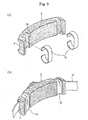
- Fig. 1 is a perspective view illustrating the general configuration of a cushion pad structure in accordance with a first embodiment of the present invention.
- the cushion pad structure comprises a cushion pad 5, and a fixing clip 10, which is integrally molded to the cushion pad 5, and is adapted to be coupled to an adjustable headband 15.
- the cushion pad 5 molded from a soft material, has a plurality of slip-prevention pieces 1, having a constant thickness, formed at an inner peripheral surface thereof, and a groove 3 formed at an outer peripheral surface thereof.
- the inner peripheral surface of the cushion pad 5 means a surface coming into contact with the wearer's head
- the outer peripheral surface thereof means a surface to be coupled to the headband 15.
- slip-prevention pieces 1 are variable in shape without being limited to that shown in Fig. 1, and thus may be shaped into vertical or horizontal recesses, or corrugated or crucial portions.
- the fixing clip 10 which is configured to be engaged in the groove 3 of the cushion pad 5, is formed, using an injection molding process, such that it is integral with the cushion pad 5.
- the fixing clip 10 is molded from a thin steel plate or synthetic resins having a high durability and elasticity. Both lateral ends of the fixing clip 10 are cut out in their middle regions, so as to define fastening pieces 7 at their upper and lower edges. Upper ones of the fastening pieces 7 have an inverted U-shaped cross sectional shape, and the other lower ones have a U-shaped cross sectional shape, so as to be coupled to a clamp member 13 constituting the headband 15.
- the cushion pad 5 and the fixing clip 10 are separately manufactured, and then are formed so as to be integral with each other using an injection molding machine.
- the fastening pieces 7, protruding laterally from both the lateral ends of the fixing clip 10, are fitted to upper and lower edges of the clamp member 13, resulting in a firm fixation of the cushion pad structure.
- Figs. 2a and 2b illustrate a cushion pad structure in accordance with a second embodiment of the present invention.
- elements similar to those of the previous embodiment are denoted by the same reference numerals as them.
- a cushion pad 5 and a fixing clip 10 of the present embodiment are separately formed using an injection molding process, and then are coupled to each other.
- the fixing clip 10 is adapted to be coupled to an inner peripheral side of the cushion pad 5.
- the cushion pad 5 has a plurality of protrusions 2 formed at the inner peripheral surface thereof, and at an outer peripheral surface of the cushion pad 5 is defined a groove 3.
- the groove 3 of the cushion pad 5 is configured to receive the clamp member 13 therein.
- the fixing clip 10 is formed with a plurality of through holes 8 having the same shape as that of the protrusions 2 formed at the cushion pad 5, and U-shaped fastening pieces 7 at both lateral ends thereof.
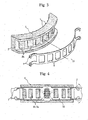
- Fig. 3 illustrates a cushion pad structure in accordance with a third embodiment of the present invention wherein elements similar to those of the previous embodiments are denoted by the same reference numerals as them.
- a fixing clip 10 is positioned to be coupled to an outer peripheral surface of a cushion pad 5.
- the cushion pad 5 has a plurality of slip-prevention pieces 1 formed at an inner peripheral surface thereof, and a plurality of protruding pieces 3 formed inside a groove 3 defined at the outer peripheral surface thereof.
- the fixing clip 10, to be integrally coupled to the cushion pad 5, has a plurality of through holes 8 having the same shape as that of the protruding pieces 3a formed at the cushion pad 5, and U-shaped fastening pieces 7 formed at upper and lower edges of both lateral ends thereof.
- the coupling of the cushion pad 5 and fixing clip 10 is performed in the same manner as that of the above second embodiment.
- the fixing clip 10 can be elastically deformed as shown in Fig. 4.
- the upper and lower fastening pieces 7 are vertically bent by virtue of their elasticity, thereby allowing the fixing clip 10 to be coupled to the clamp member 13 with a good coupling efficiency equal to that of the previous embodiments.
- FIGs. 5a and 5b illustrate a cushion pad structure in accordance with a fourth embodiment of the present invention.
- elements similar to those of the previous embodiments are denoted by the same reference numerals as them.
- a cushion pad 5 of the present embodiment is formed with upper and lower fastening slots 4 near both lateral ends thereof, whereas a pair of fixing clips 10 are configured to be inserted through the upper and lower fastening slots 4, so as to integrally couple the cushion pad 5 to the clamp member 13.
- the fixing clips 10 are formed to have an approximately C-shape, and have elasticity suitable for integrally coupling the cushion pad 5 to the clamp member 13.
- Figs. 6a and 6b illustrate a cushion pad structure in accordance with a fifth embodiment of the present invention.
- the present embodiment is similar to the fourth embodiment except for the fastening slots of the fourth embodiment are substituted for vertical grooves. Therefore, in the present embodiment, elements similar to those of the previous embodiments are denoted by the same reference numerals as them.
- a cushion pad 5 is formed at both lateral ends thereof with vertical grooves 4a, respectively.
- the cushion pad 5 is integrally coupled to the clamp member 13 with a good coupling efficiency equal to that of the previous embodiments.
- the cushion pad structure adapted to be coupled to the clamp member 13; the cushion pad structure may be coupled to a support member 14 constituting the headband in the same manner as stated above as operator's demands.
- the present invention provides a cushion pad structure which is configured so that a cushion pad thereof is detachably coupled to a clamp member or support member constituting a headband by means of a fixing clip or fixing clips, thereby maintaining the uniform balance of the headband, and securing stable wearing of protective equipment, such as a safety hat or welding mask, on a wearer's head without causing biasing thereof.
Landscapes
- Helmets And Other Head Coverings (AREA)
- Headphones And Earphones (AREA)
- Details Of Garments (AREA)
Applications Claiming Priority (2)
| Application Number | Priority Date | Filing Date | Title |
|---|---|---|---|
| KR20-2003-0013313U KR200321913Y1 (ko) | 2003-04-29 | 2003-04-29 | 헤드밴드용 쿠션패드의 구조 |
| KR2003013313 | 2003-04-29 |
Publications (1)
| Publication Number | Publication Date |
|---|---|
| EP1472943A2 true EP1472943A2 (fr) | 2004-11-03 |
Family
ID=32985746
Family Applications (1)
| Application Number | Title | Priority Date | Filing Date |
|---|---|---|---|
| EP04009755A Withdrawn EP1472943A2 (fr) | 2003-04-29 | 2004-04-24 | Coussin de rembourrage pour bandeau |
Country Status (3)
| Country | Link |
|---|---|
| US (1) | US6966074B2 (fr) |
| EP (1) | EP1472943A2 (fr) |
| KR (1) | KR200321913Y1 (fr) |
Cited By (1)
| Publication number | Priority date | Publication date | Assignee | Title |
|---|---|---|---|---|
| WO2009020583A1 (fr) * | 2007-08-06 | 2009-02-12 | Xenith, Llc | Système de fixation de harnais |
Families Citing this family (55)
| Publication number | Priority date | Publication date | Assignee | Title |
|---|---|---|---|---|
| US20050109342A1 (en) * | 2003-11-20 | 2005-05-26 | Vital Signs Inc. | Mask with elastic headband |
| US7222374B2 (en) * | 2004-05-26 | 2007-05-29 | Bell Sports, Inc. | Head gear fitting system |
| US7213271B1 (en) * | 2004-08-09 | 2007-05-08 | E.D. Bullard Company | Brow pad for the headband of protective headgear |
| US20100258132A1 (en) * | 2005-09-22 | 2010-10-14 | Karen Leigh Moore | Headgear pad for CPAP interface |
| USD551961S1 (en) * | 2005-10-18 | 2007-10-02 | Otos Tech Co., Ltd. | Rotary shaft nut of a welding mask |
| US8584265B2 (en) * | 2006-04-18 | 2013-11-19 | 3M Innovative Properties Company | Head suspension system and headgear with replaceable headband bridge and method of adjusting same |
| DE202006007041U1 (de) * | 2006-04-28 | 2006-07-27 | Ako - Kunststoffe Alfred Kolb Gmbh | Kopfgurt |
| JP5004729B2 (ja) * | 2007-09-10 | 2012-08-22 | キヤノン株式会社 | 頭部装着型機器 |
| SI2207445T1 (sl) | 2007-10-10 | 2012-09-28 | 3M Innovative Properties Co | Naglavni nosilni pas |
| US20090229041A1 (en) * | 2008-03-13 | 2009-09-17 | Welch Allyn, Inc. | Head worn apparatus |
| US8359672B2 (en) | 2008-10-21 | 2013-01-29 | Kimberly-Clark Worldwide, Inc. | Headband with pivotal pad |
| GB2473062B (en) * | 2009-08-28 | 2014-03-12 | Strategic Sports Ltd | Helmet strap |
| US8370967B2 (en) * | 2009-10-21 | 2013-02-12 | Minson Enterprises Co., Ltd. | Adjustable head band for a helmet |
| US8359668B2 (en) * | 2010-02-05 | 2013-01-29 | Vernal George Elliott | Hat traction sweatband |
| US8899774B2 (en) | 2010-11-17 | 2014-12-02 | Integra Lifesciences Corporation | Wearable headlight devices and related methods |
| KR101253075B1 (ko) * | 2010-12-13 | 2013-04-10 | 주식회사 오토스윙 | 헤드 밴드 |
| USD696469S1 (en) * | 2011-01-11 | 2013-12-24 | Pfanner Schutzbekleidung Gmbh | Helmet liner |
| USD659292S1 (en) | 2011-10-10 | 2012-05-08 | Bryan Family Enterprises LLC | Bike helmet brim |
| US9149085B2 (en) | 2011-02-21 | 2015-10-06 | Bryan Family Enterprises LLC | Brim for attaching to headgear |
| USD672096S1 (en) | 2011-10-10 | 2012-12-04 | Bryan Family Enterprises LLC | Sports helmet brim |
| US8850624B2 (en) | 2011-05-23 | 2014-10-07 | Honeywell International, Inc. | Headgear with a spring buffered occipital cradle |
| US8393014B1 (en) * | 2011-09-22 | 2013-03-12 | Leonardo Follo | Sweat absorption assembly |
| KR101331421B1 (ko) | 2011-11-04 | 2013-11-20 | 주식회사 오토스윙 | 헤드밴드용 기능성 쿠션 |
| WO2013096384A1 (fr) | 2011-12-20 | 2013-06-27 | Bryan Family Enterprises, LLC | Appareil de fixation d'accessoires de couvre-chef |
| US9021616B2 (en) * | 2012-04-25 | 2015-05-05 | David Baty | Protective gear |
| US9554610B2 (en) * | 2012-10-11 | 2017-01-31 | Honeywell International, Inc. | Protective headgear assembly |
| USD720892S1 (en) | 2013-07-23 | 2015-01-06 | Bryan Family Enterprises LLC | Headgear brim |
| US9949522B2 (en) * | 2013-08-30 | 2018-04-24 | Msa Technology, Llc | Suspension connection arrangement for a suspension system of a safety helmet |
| USD710545S1 (en) * | 2013-12-16 | 2014-08-05 | Tecmen Electronics Co., Ltd. | Head belt |
| USD710546S1 (en) * | 2013-12-16 | 2014-08-05 | Tecmen Electronics Co., Ltd. | Head belt |
| KR101594146B1 (ko) * | 2014-05-15 | 2016-02-15 | 주식회사 오토스윙 | 헤드 밴드용 기능성/다용도 헤드 쿠션 |
| KR101594145B1 (ko) | 2014-05-15 | 2016-02-26 | 주식회사 오토스윙 | 기능성 쿠션 케이스 일체형 헤드 밴드 |
| US10390582B2 (en) | 2014-12-05 | 2019-08-27 | Two Guys And A Hat Inc. | Protective headgear |
| USD767829S1 (en) | 2015-02-04 | 2016-09-27 | Tecmen Electronics Co., Ltd. | Belt for welding helmet |
| ITUB20154758A1 (it) * | 2015-10-27 | 2017-04-27 | Kask Spa | Fascia poggia fronte per caschi e casco provvisto di tale fascia poggia fronte. |
| US10729202B2 (en) * | 2016-08-10 | 2020-08-04 | Tecmen Electronics Co., Ltd. | Headband arrangement and welding helmet equipped with the same |
| AU2017200061B2 (en) * | 2016-08-10 | 2019-12-19 | Tecmen Electronics Co., Ltd | Headband arrangement and welding helmet equipped with the same |
| KR101791359B1 (ko) | 2016-10-26 | 2017-10-27 | 김을수 | 머리보호대 |
| US10149509B2 (en) * | 2016-12-28 | 2018-12-11 | Otos Wing Co., Ltd. | Ergonomic occipital triangular cushion pad for head bands |
| USD870977S1 (en) | 2017-09-22 | 2019-12-24 | 3M Innovative Properties Company | Headband |
| USD852470S1 (en) | 2018-03-21 | 2019-07-02 | 3M Innovative Properties Company | Sweatband |
| USD917841S1 (en) * | 2018-09-22 | 2021-05-04 | Snaps Ventures Inc. | Snap attachment for a cap |
| USD884236S1 (en) | 2018-10-04 | 2020-05-12 | Integra Lifesciences Corporation | Wearable headgear device |
| EP3861250B1 (fr) | 2018-10-04 | 2025-01-22 | Integra LifeSciences Corporation | Dispositifs pouvant être portés sur la tête et procédés |
| USD901737S1 (en) | 2018-10-04 | 2020-11-10 | Integra Lifesciences Corporation | Wearable headgear device |
| US11224260B2 (en) * | 2018-11-20 | 2022-01-18 | Russ Inouye | Removable (and optionally washable) hat insert for absorbing perspiration |
| USD895937S1 (en) * | 2019-02-14 | 2020-09-15 | Snaps Ventures Inc. | Attachment for a cap |
| KR102151712B1 (ko) * | 2019-06-14 | 2020-09-04 | 주식회사 오토스윙 | 헤드 밴드 |
| RU194740U1 (ru) * | 2019-06-27 | 2019-12-23 | федеральное государственное бюджетное образовательное учреждение высшего образования "Самарский государственный технический университет" | Головное крепление навесного оборудования |
| EP3760071A1 (fr) * | 2019-07-05 | 2021-01-06 | 3M Innovative Properties Company | Casque de soudage |
| KR102296424B1 (ko) * | 2019-11-11 | 2021-09-02 | 주식회사 코브 인터내셔날 | 안전모용 머리받침 밴드 및 이를 갖는 안전모 |
| KR102476062B1 (ko) * | 2020-06-03 | 2022-12-09 | 주식회사 오토스윙 | 용접용 보호 장치 |
| US11846390B2 (en) * | 2020-06-04 | 2023-12-19 | Meta Platforms Technologies, Llc | Pass-through ratcheting mechanism |
| GB2605354A (en) * | 2021-02-09 | 2022-10-05 | World Wide Welding Ltd | Helmet |
| US12396508B2 (en) | 2023-05-18 | 2025-08-26 | Honeywell Safety Products Usa, Inc. | Suspension assembly and method of manufacture |
Family Cites Families (9)
| Publication number | Priority date | Publication date | Assignee | Title |
|---|---|---|---|---|
| US3046559A (en) * | 1958-06-24 | 1962-07-31 | Mine Safety Appliances Co | Protective helmet lining |
| US3289212A (en) * | 1964-12-07 | 1966-12-06 | John T Riddell Inc | Sizer means for helmets |
| US3292180A (en) * | 1964-12-15 | 1966-12-20 | Michael T Marietta | Helmet |
| US4259747A (en) * | 1979-06-27 | 1981-04-07 | The United States Of America As Represented By The Secretary Of The Navy | Protective communications helmet |
| DE3516581C2 (de) * | 1985-05-08 | 1987-03-12 | Heine Optotechnik Gmbh & Co Kg, 8036 Herrsching | Kopfband mit Polster |
| US4884301A (en) * | 1988-06-13 | 1989-12-05 | Gentex Corporation | Combination chinstrap-napestrap assembly for helmet |
| US5025504A (en) * | 1988-12-16 | 1991-06-25 | Weyerhaeuser Company | Liner for a helmet, hat, cap or other head covering |
| US5474487A (en) * | 1993-03-30 | 1995-12-12 | Roush; Warren H. | Brassiere strap bridging and support member |
| US5926849A (en) * | 1998-03-31 | 1999-07-27 | Boyle; Kevin J. | Baseball cap with a channeled, laminated inside head band |
-
2003
- 2003-04-29 KR KR20-2003-0013313U patent/KR200321913Y1/ko not_active Expired - Lifetime
-
2004
- 2004-04-22 US US10/830,159 patent/US6966074B2/en not_active Expired - Lifetime
- 2004-04-24 EP EP04009755A patent/EP1472943A2/fr not_active Withdrawn
Cited By (2)
| Publication number | Priority date | Publication date | Assignee | Title |
|---|---|---|---|---|
| WO2009020583A1 (fr) * | 2007-08-06 | 2009-02-12 | Xenith, Llc | Système de fixation de harnais |
| US7950073B2 (en) | 2007-08-06 | 2011-05-31 | Xenith, Llc | Headgear securement system |
Also Published As
| Publication number | Publication date |
|---|---|
| US20050138719A1 (en) | 2005-06-30 |
| US6966074B2 (en) | 2005-11-22 |
| KR200321913Y1 (ko) | 2003-07-31 |
Similar Documents
| Publication | Publication Date | Title |
|---|---|---|
| US6966074B2 (en) | Cushion pad structure for headband | |
| US10376011B2 (en) | Football helmet with raised plateau | |
| US8925774B2 (en) | Harness for a handheld power equipment | |
| US9132038B2 (en) | Ear warmer having a curved ear portion | |
| US7120939B1 (en) | Support for a face shield | |
| US6367085B1 (en) | Head suspension for an air supplied hood system | |
| US5608917A (en) | Ergonomic head band apparatus | |
| US20130195308A1 (en) | Ear warmer | |
| US20140078460A1 (en) | Eyeglasses and clipping device therefor | |
| US20250057278A1 (en) | Bicycle helmet with eyewear retention | |
| JPH09173377A (ja) | ゴーグル | |
| CA2527532A1 (fr) | Couche interne de revetement pour casque pare-balles | |
| US11607001B2 (en) | Wind noise reduction apparatus | |
| JP2022144931A (ja) | マスクフレームおよびマスク | |
| TWM369144U (en) | Safety mask with earmuff fixing slot | |
| CN202135768U (zh) | 附有耳罩的安全面罩调整结构 | |
| KR200183011Y1 (ko) | 안경용코받침대 | |
| JP2007075522A (ja) | 作業用マスク装着具及びヘルメット | |
| JP2004538386A (ja) | 額と頭髪に帽子を被った跡がない帽子 | |
| KR100873002B1 (ko) | 착용감을 개선시키는 모자용 탄성밴드 및 그 탄성밴드를사용한 모자 | |
| CN212393949U (zh) | 一种防护面罩 | |
| CN222070976U (zh) | 鼻托适配度高的眼镜架和光学眼镜 | |
| JP4060215B2 (ja) | ヘルメット用補助バンドとそれを使用したヘルメット | |
| KR200299369Y1 (ko) | 안전모용 턱끈의 결합구조 | |
| JPH065818Y2 (ja) | スイミングゴ−グル |
Legal Events
| Date | Code | Title | Description |
|---|---|---|---|
| PUAI | Public reference made under article 153(3) epc to a published international application that has entered the european phase |
Free format text: ORIGINAL CODE: 0009012 |
|
| AK | Designated contracting states |
Kind code of ref document: A2 Designated state(s): AT BE BG CH CY CZ DE DK EE ES FI FR GB GR HU IE IT LI LU MC NL PL PT RO SE SI SK TR |
|
| AX | Request for extension of the european patent |
Extension state: AL HR LT LV MK |
|
| STAA | Information on the status of an ep patent application or granted ep patent |
Free format text: STATUS: THE APPLICATION IS DEEMED TO BE WITHDRAWN |
|
| 18D | Application deemed to be withdrawn |
Effective date: 20061031 |