EP1473060A1 - Dispositif d'obturation et l'utilisation du dit dispositif comme barrière de sécurité en cas d'incendie - Google Patents
Dispositif d'obturation et l'utilisation du dit dispositif comme barrière de sécurité en cas d'incendie Download PDFInfo
- Publication number
- EP1473060A1 EP1473060A1 EP03405300A EP03405300A EP1473060A1 EP 1473060 A1 EP1473060 A1 EP 1473060A1 EP 03405300 A EP03405300 A EP 03405300A EP 03405300 A EP03405300 A EP 03405300A EP 1473060 A1 EP1473060 A1 EP 1473060A1
- Authority
- EP
- European Patent Office
- Prior art keywords
- shut
- tunnel
- screen
- transport device
- barrier
- Prior art date
- Legal status (The legal status is an assumption and is not a legal conclusion. Google has not performed a legal analysis and makes no representation as to the accuracy of the status listed.)
- Withdrawn
Links
Images



Classifications
-
- A—HUMAN NECESSITIES
- A62—LIFE-SAVING; FIRE-FIGHTING
- A62C—FIRE-FIGHTING
- A62C3/00—Fire prevention, containment or extinguishing specially adapted for particular objects or places
- A62C3/02—Fire prevention, containment or extinguishing specially adapted for particular objects or places for area conflagrations, e.g. forest fires, subterranean fires
- A62C3/0221—Fire prevention, containment or extinguishing specially adapted for particular objects or places for area conflagrations, e.g. forest fires, subterranean fires for tunnels
-
- A—HUMAN NECESSITIES
- A62—LIFE-SAVING; FIRE-FIGHTING
- A62C—FIRE-FIGHTING
- A62C2/00—Fire prevention or containment
- A62C2/06—Physical fire-barriers
- A62C2/10—Fire-proof curtains
Definitions
- the invention relates to a shut-off device for shutting off a Cross-sectional area in a tubular passage, in particular for Barrier in a tunnel tube, as well as the use of the Shut-off device as a safety lock in the event of fire in accordance with General term of the independent claim of the respective category.
- the lockable Sections are determined by the installation of the gates. So that sections to be blocked off with regard to their size and their position in the tunnel cannot be adjusted. In addition, usually, alone is out economic and also from a technical point of view, the number of such Barrier gates limited in the tunnel, so that only relatively large sections are lockable, which in turn leads to problems with the exchange of air in the Case of maintenance.
- the object of the invention is therefore to provide a shut-off device Shutting off a tubular passage, for example one
- a shut-off device Shutting off a tubular passage, for example one
- the invention thus relates to a shut-off device for shutting off a Cross-sectional area in a tubular passage, in particular for Barrier in a tunnel tube.
- the shut-off device comprises at least a shut-off screen which can be folded with respect to a longitudinal axis, and a transport device for positioning the shut-off screen a predefinable position in the implementation, the shut-off screen so arranged on the transport device and configured such that with the shut-off can be shut off via the cross-sectional area is.
- tunnel tube is used as Synonymous with tunnels, tunnels and tubular bushings of all kinds used.
- a tunnel tube of any kind is not only made by it Access openings are ventilated, but at certain intervals Exchange of breathing air supply and suction shafts provided through the the tunnel tube is constantly supplied with fresh air. That is, through the Supply shafts are brought into the tunnel tube from outside and fresh air transported back through the extraction shafts, whereby of course also the access openings of the tunnel into the Ventilation system are involved.
- Air exchange at the supply and suction shafts at a suitable point
- very powerful fans are provided, which bring fresh air into the Blow in or suction out the tunnel tube, so that per unit of time the amount of air exchanged can be controlled and / or regulated within certain limits.
- the supply and suction shafts ensure that in one To a certain extent, the fresh air exchange also locally within predefinable limits can be influenced.
- the barrier of the Shut-off device is by means of the transport device to any one Point of the tunnel tube can be positioned so that the tunnel tube at one can be shut off anywhere over its cross-sectional area.
- this section can be largely isolated from the rest of the tunnel, causing an exchange of air through the supply and suction shafts that in the cordoned off area, or in its vicinity in the tunnel tube are particularly effective.
- such a spread of Emissions in the tunnel tube outside the closed area are largely avoided.
- the shut-off device has one of the essential elements collapsible barrier on a transport device is mounted so that the shut-off screen to shut off a Cross-sectional area of the tunnel tube, such as a railway or Road tunnels or a tunnel in a mine or one other tubular implementation, by means of the transport device a predeterminable position can be transported.
- the transport device can for example a correspondingly modified rail vehicle like a railway wagon or a suitably modified land vehicle such as for example, a trailer of a truck or a truck be yourself.
- the transport device is preferably self-moving and includes its own travel drive. So comes as a transport device in particular a rail vehicle, such as a locomotive or a land vehicle, such as a truck in question, that later May have modifications to be described. Of course the transport device can also be used with any other suitable vehicle or without your own drive.
- the shut-off screen of the shut-off device according to the invention is as collapsible barrier designed and so on the Transport device arranged that the shut-off device at folded shut-off screen easily through the tunnel tube a predeterminable position can be placed where the barrier can be opened or unfolded so that the shut-off screen is a Cross-sectional area of the tunnel tube largely covered, and the Tunnel tube is largely blocked over the cross-sectional area.
- the shut-off screen preferably has a plurality of struts Supporting a tarpaulin, at least one strut using a Connection with a slidably and / or rotatably arranged Clamping element is connected such that the cross-sectional area at Moving and / or rotating the clamping element by the Barrier is lockable.
- the plurality of Strive for a hinged frame together with the clamping elements, the struts define an area in the unfolded state that with the tarpaulin is covered and essentially in shape and size Cross-sectional area of the cross-section of the tunnel tube to be blocked equivalent.
- the shut-off screen may open the Cross-sectional area of the tunnel tube is not completely impermeable to air to lock.
- this is hardly possible because the tunnel tube in the As a rule, certain tunnel installations, as will be explained in more detail later includes.
- the proportion of the covered area also less than 90%, in in particular more than 80% and less than 90% or in particular also be greater than 95%.
- 125 mbar which means that, for example, in a railway tunnel with a typical cross-sectional area of approx. 42m 2, a pushing force of 500 KN essentially acting along the longitudinal axis of the blocking device and can act more on the shut-off device.
- the values given here as examples can of course vary greatly depending on the geometry and size of the cross-sectional area, the area effectively covered by the shut-off screen and the strength of the air exchange.
- the Shut-off device in a special embodiment on the Transport device at least one support for anchoring in the include tubular feedthrough.
- the strength of the thrust on the Shut-off device due to differences in air pressure on both sides of the barrier can take on considerable values, as a rule without further measures, the shut-off device in the tunnel tube would not fixable, that is, the shut-off device would under the effect of Move thrust.
- supports can be provided on the transport device the wall of the tunnel tube can be supported so that the thrust on the Shut-off device can be compensated.
- the supports are preferred executed and arranged on the transport device that the supports without special structural measures on the wall of the tunnel tube are necessary, can be anchored non-slip. This is the Shut-off device very flexible at any position in the Tunnel tube securely fixable.
- the wall of the Tunnel tube also appropriate facilities, such as suitable Have attachments or recesses in the tunnel wall in which the Support is particularly well anchored.
- the supports are movable arranged of the transport device and either by hand or hydraulically or pneumatically or for example by means of an electrical Drive can be positioned on the wall of the tunnel tube.
- This will not only open the Barrier screen by the pressure difference, or by the building up Pressure difference when opening the shut-off screen, advantageous supported, but the pressure difference helps when the shut-off screen is open between both sides of the barrier also making sure that the Barrier remains stable when open and in predefinable Areas sealingly abuts the wall of the tunnel tube.
- the shut-off device is usually referenced in the operating state positioned on its longitudinal axis in the tunnel tube so that the higher one Air pressure acts on the shut-off screen so that the pressure difference between the higher air pressure on one side of the barrier and a lower negative pressure on the other side of the barrier, that Advantageously supported opening of the screen.
- the Shut-off device equipped with a closable passage opening, the one, not necessarily completely enclosed, interior of the Transport device with an area outside the shut-off device connects, the passage opening as a lock with a Lock chamber and at least two lock gates can.
- the passage opening mentioned above can advantageously be provided.
- the Passage opening for example in the form of a lock gate Sliding door is designed so that the operation of the lock gate is not is made more difficult by the pressure difference, even when opened Barrier screen the cordoned section of tunnel left by personnel or can be entered and there can be working material, operating materials and so on through the passage opening.
- the Passage opening can be designed as a lock, which is known per se Way as a personal or material lock comprises two lock gates that limit a lock chamber.
- the passage opening is designed with a lock chamber particularly advantageous if, for example, high pressure differences rule between both sides of the barrier, or an exchange the air must be avoidable when the outlet opening is open.
- a lock can be used advantageously because it for example the exchange of smoke, toxic gases and so on is largely avoidable
- the lock can also special devices, for example through suction devices such as Fans or the like, for exchanging the air in the lock chamber have so that contaminants that have entered the lock chamber before Opening the lock chamber are removable from this.
- Locking device the lock also missing, so only one Passage opening with a lock gate is present. Beyond that in special cases it is also possible that the shut-off device at all has no passage opening
- the shut-off device can also be designed such that the Transport device comprises two or more shut-off screens. So can for example one and the same transport device in relation to the Longitudinal axis on two opposite sides each one or more Barriers include. That can be an advantage if the area the tunnel tube, in which, for example, maintenance work is carried out, is very limited so that the length of the transport device is sufficient to to cover the work area.
- the Shutoff device according to the invention also very much is advantageously used if, for example, in a tunnel tube with harmful emissions, such as smoke, is a pollutant free space must be created. So can in a pollutant contaminated tunnel tube in which work in a certain area must be carried out by appropriate use of the Shut-off device according to the invention, a largely pollutant-free Create an area in which work can be done safely. In this case, it may be advantageous to have several shields in a row to be provided on the transport device so that the penetration of Pollutants in the cordoned off work area becomes even more effective.
- the shut-off device according to the invention also as a safety lock in the event of a fire, for mobile use Blocking of a cross-sectional area in a tubular passage, in particular a railway tunnel or a road tunnel or one Stollen used in a mine.
- the barrier is preferably from a heat and / or fire made of durable material.
- control means for remote control of the shut-off device in particular for remote control of the shut-off screen and / or the Transport device and / or certain facilities that the Shut-off device can be provided.
- Fig. 1 shows a schematic representation of two according to the invention
- Shut-off devices which shut-off device as a whole in the following is designated by the reference numeral 1
- the a tunnel section 31 a Limit tunnel tube 3 on both sides, as shown on the right and left.
- the Tunnel section 31 are between the two shut-off devices 1 for example, maintenance work associated with emissions.
- the blocking device 1 for blocking a Cross-sectional area 2 in the tunnel tube 3, as shown in FIG. 1, comprises at least one with respect to a longitudinal axis 4 of the tunnel tube 3 collapsible shut-off screen 5, and a transport device 6 for Positioning of the shut-off screen 5 at a predeterminable position in the Tunnel tube 3, with the barrier screen 5 on the transport device 6 is arranged and designed such that with the shut-off screen 5 Tunnel tube 3 can be shut off over the cross-sectional area 2.
- the two shut-off devices 1 are in the tunnel tube 3, the under other, for example, a railway tunnel 3, a road tunnel 3 or a Tunnel 3 of a mine can be positioned in that by the Shut-off devices 1 limited tunnel section 31, a suction shaft 32 for extracting air 15 and / or, as not shown here, a Supply shaft for the supply of fresh air 151, is available.
- the Barriers 5 in the illustration of FIG. 1 are opened, so that according to its position in the tunnel tube 3, the tunnel section 31 delimit each against the rest of the tunnel tube 3.
- Supply shafts 33 for the supply of fresh air 151 are arranged.
- the shut-off screen 5 in the opened state Cross-sectional area 2 of the tunnel tube 3 is not completely impermeable to air to lock.
- the tunnel tube 3 such as will be explained in more detail later, may include certain tunnels.
- there must of course be a permanent air exchange between the Tunnel section 31 and the area of the tunnel tube 3 outside the Tunnel section 31 may be possible, otherwise the fresh air 151 is not in the Tunnel section 31 and ultimately no air exchange in the Tunnel section 31 is possible, i.e. also removing the emissions the tunnel section 31 would not be possible.
- the Barrier 5 Preferably covers the Barrier 5 in the open state about 90% - 95% of Cross-sectional area 2 of the tunnel tube 3, so that on the one hand the Tunnel section 31 sufficiently against the rest of the tunnel tube 3 is sealed off and, on the other hand, a sufficiently large air exchange is possible.
- the proportion of covered area also less than 90%, for example more than 80% and be less than 90% or in particular also be greater than 95%.
- the value of the air pressure P 2 is always at least as great, but preferably greater than the value of the negative pressure P 1 . If, when the shut-off screen 5 is open, the negative pressure P 1 prevails in the tunnel section 31, the air pressure P 2 prevails outside the tunnel section 31 and vice versa.
- the air pressure difference between the tunnel section 31 and the area outside the tunnel section 31 thus results as the difference between the pressure values P 1 and P 2 .
- a typical value for the air pressure difference between the blocked-off tunnel section 31 and the tunnel tube 3 outside may, for example, be approximately 125 mbar, which, for example, results in a thrust force acting essentially along the longitudinal axis 4 in a railway tunnel 3 with a typical cross-sectional area 2 of approximately 42 m 2 of 500 KN and more can act on the shut-off device 1.
- the values given here by way of example can of course vary widely depending on the geometry and size of the cross-sectional area 2, the area effectively covered by the shut-off screen 5 and the strength of the air exchange.
- the force effects described above due to the air pressure difference must of course, as will be described in more detail below, possibly be compensated for by suitable measures.
- Fig. 1 a is another typical application for the Shut-off device 1 according to the invention is shown schematically.
- the tunnel section 31 may be useful to the tunnel section 31 only one side to block off the rest of the tunnel and the Tunnel exit A as supply shaft 33 for supplying fresh air 151 use.
- the fresh air 151 then flows as shown by way of example in FIG. 1 a through the tunnel exit A into the tunnel section 31 and with Emissions-polluted air 5 is again via the suction shaft 32 dissipated.
- the air 151 over the Tunnel exit A is discharged and instead of or in addition to Suction shaft 32 in the tunnel section 31, a feed shaft 33 is provided is.
- the Barrier screen 5 preferably in the opening direction with a higher air pressure depending on the direction of the Air pressure gradient, the shut-off device 1 with respect to its longitudinal axis 4 be positioned accordingly in the tunnel tube 3.
- FIG. 1b Another embodiment according to FIG. 1 is shown schematically in FIG. 1b shown.
- the tunnel section 31 is shown on the right and left limited by a shut-off device, both the feed shaft 33 for the supply of fresh air 151, as well as the suction shaft 32 for Air discharge 15 are arranged between the shut-off devices 1. That is, in the tunnel section 31, a substantially closed one Air exchange takes place. A corresponding pressure drop arises among other things, depending on the distance of the suction shaft 32 to the feed chute 33 essentially independently.
- Fig. 1 b is the air in the tunnel section 31 regardless of the air circulation in the remaining part of the tunnel tube 3, can be recirculated in the tunnel section 31.
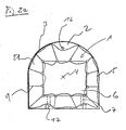
- FIG. 2 schematically shows an exemplary embodiment of a shut-off device 1 with the shut-off screen 5 in a tunnel tube 3 in longitudinal section, in Fig. 2a shows the same embodiment in cross section.
- the tunnel tube 3 is a railway tunnel 3, among other things, appropriate tunnel installations such as an electrical one Catenary 16 for supplying rail vehicles with electrical Energy and tracks 17 includes.
- the transport device 6 is a Rail vehicle 6, which comprises its own travel drive 7, which for Drive include an electric motor, not shown here, for example can, which is preferably independent of the electrical contact line 16 is operable.
- an electric motor not shown here, for example can, which is preferably independent of the electrical contact line 16 is operable.
- the transport device 6 also an internal combustion engine can include as a drive 7 or that in another embodiment according to FIG.
- the transport device 6 does not have to have its own travel drive 7.
- control means not shown here, for remote control of the Shut-off device 1, in particular for remote control of the shut-off screen 5 and or the Trannsportvorides 6 are provided. That's the way it is For example, it is possible that the shut-off screen 5 is opened remotely or is closed and / or that the transport device 6 is remotely controlled is movable.
- the shut-off screen 5 of the shut-off device 1 comprises a screen tarpaulin 51, which is supported and stretched by struts 9.
- the tarpaulin 51 is preferably constructed from a flexible, tear-resistant material that on the one hand has a good kink behavior, so that the shut-off screen 5 with the screen tarpaulin 51 is easily collapsible and any existing Tunnel installations on or near the walls of the tunnel, such as lamps, electrical catenary, rails, pipes, etc. through the tarpaulin 51 flexible and can be enclosed without damage.
- tarpaulins commercial truck tarpaulin in question, especially tarpaulin with a Base fabric according to DIN 60001, such as the one under the name Trevira Novo known tarpaulin material.
- tarpaulin materials especially carbon composite materials possible; the above-mentioned tarpaulin materials are only examples understand.
- non-flammable materials with a high melting point, for example fabrics made of ceramics, and possibly heat reflecting Coatings on the fabric or tarpaulin.
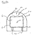
- the schematic cross-sectional illustration according to FIG. 2a is special easy to see how the tarpaulin 51 in the opened state of the Barrier 5 covers the cross section 2 of the tunnel tube 3.
- the Shield tarpaulin 51 encloses tunnels, such as the electrical catenary 16 and the rails 17 flexible and without them to damage.
- the shut-off screen 5 can additionally not shown here Support elements 9 for supporting the tarpaulin 51 in the area of Include tunnel internals, so that the tarpaulin 51 the tunnel internals encloses without exerting significant forces on them.
- FIG. 3 shows a further exemplary embodiment according to FIG. 2 in a top view, at least one support 8 being provided on the transport device 6 for anchoring in the tubular passage 3.
- the negative pressure P 1 prevails in the tunnel section 31, as shown on the right side of the shut-off screen 5, while the greater air pressure P 2 prevails to the right of the screen. Since the air pressure P 2 is greater than the vacuum P 1 , a thrust force F acts on the shut-off device 1 or on the shut-off screen 5 in the direction from the larger air pressure P 2 to the smaller vacuum P 1 .
- the effect of the thrust force F is indicated schematically in Fig. 3 by the arrow.
- the blocking device 1 cannot be fixed in the tunnel tube 3, that is, the shut-off device 1 would under the effect of Thrust F in the example shown in FIG move left to right or experience the corresponding torques.
- the Transport device 6 supports 8 provided on the wall of the Tunnel tube 3 can be supported, so that the thrust F on the Shut-off device 1 can be compensated.
- the supports 8 are preferably so executed and arranged on the transport device 6 that the supports 8th without special structural measures on the wall of the tunnel tube 3 are necessary, can be anchored non-slip.
- the wall of the tunnel tube 3 also appropriate facilities, such as for example, suitable attachments or recesses in the tunnel wall have, in which the support 8 is particularly well anchored.
- the shut-off device 1 in the operating state, is generally positioned in the tunnel tube 3 with respect to the longitudinal axis 4 such that the higher air pressure P 2 acts on the shut-off screen 5 in such a way that the pressure difference between the higher air pressure P 2 on one side of the Barrier screen 5 and the lower negative pressure P 1 on the other side of the barrier screen 5, advantageously supports the opening of the barrier screen 5.
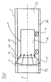
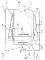
- Fig. 4 is a shut-off device 1 in a schematic representation closable passage opening 12 into an interior 13 of the Transport device 6 outlines, the passage opening 12 as a lock 14 with a lock chamber 141 and at least two lock gates 142 is designed.
- the tunnel section 31 even when the barrier is open Entering or leaving 5 is, as shown schematically in FIG. 4, on the shut-off device 1 is advantageously provided with a passage opening 12.
- the passage opening 12 which acts as a lock gate 142, for example in Form of a sliding door 142 is formed so that the operation of the Lock gate 142 is not complicated by the pressure difference, can also with the barrier 5 open, the tunnel section 31 by the personnel be left or entered and there may be working materials, operating materials and so on through the passage opening 12.
- the passage opening 12 as Lock 14 may be formed, the person or in a known manner
- Material lock comprises two lock gates 142, one Limit lock chamber 141.
- the configuration of the passage opening 12 with a lock chamber 14 is particularly advantageous if, for example, high pressure differences prevail between both sides of the shut-off screen 5, or an exchange the air must be avoidable when the passage opening 12 is open.
- the shut-off device 1 as a safety lock 1 in the Fire event for the mobile blocking of a cross-sectional area 2 of the tubular bushing 3, in particular a road tunnel 3 or a tunnel 3 is used in a mine
- a lock 14 the exchange of Smoke, toxic gases and so on is largely avoidable.
- Particularly can also lock 14 via special devices, for example Suction devices such as fans or the like, for exchanging the air have in the lock chamber 141, so that in the lock chamber 141 contaminants that have entered before opening the lock chamber 141 from it are removable.
- Locking device 1 the lock 14 is also missing, so that only one Passage opening 12 with a lock gate 142 is present.
- the shut-off device 1 has no passage opening 12.
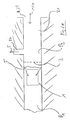
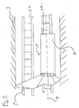
- FIG. 4 is a special embodiment of a Barrier screen 5 shown in a schematic manner, the Barrier 5 a plurality of struts 9 to support the Includes tarpaulin 51, and at least one strut 9 by means of a Connection 10 with a slidably and / or rotatably arranged Clamping element 11 is connected such that the cross-sectional area 2 when Moving and / or rotating the clamping element 11 by the Barrier screen 5 is lockable.
- Shut-off device 1 is the clamping element 11 with a sliding element 111 connected, the along a, attached to the transport device, Bracket 112 is slidably disposed.
- the strut 9 By moving the Sliding element 111, as shown to the right, the strut 9, the for example, at a predeterminable point on the one hand with the Clamping element 11 and is connected at one end to the holder 12, moved outwards from the transport device 6, whereby the Barrier 5 is spanned by the struts 9.
- the Shifting the sliding element 111 or opening the shut-off screen 5 can be accomplished by hand, but preferred, not here shown, drive devices for opening the shut-off screen 5 are provided, for example by means of electric motors, possibly under Use of suitable gears, but especially hydraulic or are pneumatically actuated.
- drive devices for opening the shut-off screen 5 are provided, for example by means of electric motors, possibly under Use of suitable gears, but especially hydraulic or are pneumatically actuated.
- remote control devices can be provided that it allow the shut-off screen 5 to be controlled remotely, for example from outside the tunnel tube 3 from opening or closing.
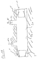
- FIG. 5 finally shows a special representation in a schematic representation Embodiment of a shut-off screen 5 according to the invention, the is designed asymmetrically with respect to the longitudinal axis 4.
- This special Embodiment can be used advantageously in particular if the transport device 6 with respect to a longitudinal axis of the Tunnel tube 3 can only be positioned asymmetrically. Examples of this are below another a tunnel tube 3 of a railroad tunnel or gallery 3 of a mine with several tracks 17 running in parallel Road tunnel 3 with several parallel lanes or similar examples.
- the radius of the shut-off screen 5 can then vary in the circumferential direction, so that the shut-off screen 5 in the opened state even with asymmetrical Positioning of the transport device 6 in the tunnel tube 3 den Cross section 2 still optimally closed off.
- shut-off device By using the shut-off device according to the invention, it is possible, the problems known from the prior art, the for example in the case of emission-related maintenance work in one Tunnel tubes occur, easily and inexpensively, in a particularly efficient manner Way to avoid.
- the barrier of the invention Locking device is by means of the transport device on any Point of the tunnel tube can be positioned so that the tunnel tube at one can be shut off anywhere over its cross-sectional area.
- this section can be largely isolated from the rest of the tunnel, causing an exchange of air through the supply and suction shafts that in the cordoned off area, or in its vicinity in the tunnel tube are particularly effective.
- such a spread of Emissions in the tunnel tube outside the closed area are largely avoided.
- shut-off device in a polluted environment in a tunnel with a room largely unpolluted ambient air can be created in which To stop people safely.
- the method according to the invention can be used in a particularly advantageous manner Shutdown device also as a safety lock in the event of fire for mobile Blocking of a cross-sectional area in a tubular passage, in particular a railway tunnel or a road tunnel or one Stollen used in a mine.
- the shut-off device is in its function as a safety barrier other than as a fire barrier or for example as smoke protection used.
Landscapes
- Health & Medical Sciences (AREA)
- Public Health (AREA)
- Business, Economics & Management (AREA)
- Emergency Management (AREA)
- Life Sciences & Earth Sciences (AREA)
- Biodiversity & Conservation Biology (AREA)
- Ecology (AREA)
- Forests & Forestry (AREA)
- Lining And Supports For Tunnels (AREA)
Priority Applications (1)
| Application Number | Priority Date | Filing Date | Title |
|---|---|---|---|
| EP03405300A EP1473060A1 (fr) | 2003-04-29 | 2003-04-29 | Dispositif d'obturation et l'utilisation du dit dispositif comme barrière de sécurité en cas d'incendie |
Applications Claiming Priority (1)
| Application Number | Priority Date | Filing Date | Title |
|---|---|---|---|
| EP03405300A EP1473060A1 (fr) | 2003-04-29 | 2003-04-29 | Dispositif d'obturation et l'utilisation du dit dispositif comme barrière de sécurité en cas d'incendie |
Publications (1)
| Publication Number | Publication Date |
|---|---|
| EP1473060A1 true EP1473060A1 (fr) | 2004-11-03 |
Family
ID=32982016
Family Applications (1)
| Application Number | Title | Priority Date | Filing Date |
|---|---|---|---|
| EP03405300A Withdrawn EP1473060A1 (fr) | 2003-04-29 | 2003-04-29 | Dispositif d'obturation et l'utilisation du dit dispositif comme barrière de sécurité en cas d'incendie |
Country Status (1)
| Country | Link |
|---|---|
| EP (1) | EP1473060A1 (fr) |
Cited By (3)
| Publication number | Priority date | Publication date | Assignee | Title |
|---|---|---|---|---|
| WO2006043889A1 (fr) | 2004-10-19 | 2006-04-27 | Maria Kumm | Gaine de tunnel pour tunnel permettant une ventilation controlee des gaz |
| WO2008040855A1 (fr) * | 2006-10-06 | 2008-04-10 | Simultron Oy | Dispositif pour améliorer le fonctionnement d'une unité de ventilateur dans un tunnel ou un autre espace muni d'une ouverture de grande dimension |
| EP2243925A1 (fr) * | 2009-04-16 | 2010-10-27 | Montes S.r.l. | Appareil de filtrage d'air dans les tunnels |
Citations (4)
| Publication number | Priority date | Publication date | Assignee | Title |
|---|---|---|---|---|
| GB2056012A (en) * | 1979-08-07 | 1981-03-11 | Kurukulasuriya M | Stopper to Block Circular Pipes Tunnels etc. |
| FR2524327A1 (fr) * | 1982-03-31 | 1983-10-07 | Dromigny Pierre | Procede de protection vis-a-vis d'un incendie dans un tunnel et vehicule permettant sa mise en oeuvre |
| RU2136889C1 (ru) * | 1996-02-05 | 1999-09-10 | Российский научно-исследовательский институт горноспасательного дела (РосНИИГД) | Способ тушения пожара в куполе горной выработки шахты |
| EP1166823A2 (fr) * | 2000-06-19 | 2002-01-02 | Rosenbauer International Aktiengesellschaft | Appareil d'insertion et méthode de déplacement de masses d'air contaminé |
-
2003
- 2003-04-29 EP EP03405300A patent/EP1473060A1/fr not_active Withdrawn
Patent Citations (4)
| Publication number | Priority date | Publication date | Assignee | Title |
|---|---|---|---|---|
| GB2056012A (en) * | 1979-08-07 | 1981-03-11 | Kurukulasuriya M | Stopper to Block Circular Pipes Tunnels etc. |
| FR2524327A1 (fr) * | 1982-03-31 | 1983-10-07 | Dromigny Pierre | Procede de protection vis-a-vis d'un incendie dans un tunnel et vehicule permettant sa mise en oeuvre |
| RU2136889C1 (ru) * | 1996-02-05 | 1999-09-10 | Российский научно-исследовательский институт горноспасательного дела (РосНИИГД) | Способ тушения пожара в куполе горной выработки шахты |
| EP1166823A2 (fr) * | 2000-06-19 | 2002-01-02 | Rosenbauer International Aktiengesellschaft | Appareil d'insertion et méthode de déplacement de masses d'air contaminé |
Cited By (3)
| Publication number | Priority date | Publication date | Assignee | Title |
|---|---|---|---|---|
| WO2006043889A1 (fr) | 2004-10-19 | 2006-04-27 | Maria Kumm | Gaine de tunnel pour tunnel permettant une ventilation controlee des gaz |
| WO2008040855A1 (fr) * | 2006-10-06 | 2008-04-10 | Simultron Oy | Dispositif pour améliorer le fonctionnement d'une unité de ventilateur dans un tunnel ou un autre espace muni d'une ouverture de grande dimension |
| EP2243925A1 (fr) * | 2009-04-16 | 2010-10-27 | Montes S.r.l. | Appareil de filtrage d'air dans les tunnels |
Similar Documents
| Publication | Publication Date | Title |
|---|---|---|
| EP3067633B1 (fr) | Procede de decontamination | |
| DD296210A5 (de) | Verfahren und einrichtung zur entfernung fluechtiger schadstoffe aus erdboeden und vergleichbaren materialien | |
| DE202017007234U1 (de) | Anschlussvorrichtung zum Anschluss an einen Arbeitsraum | |
| DE202020103567U1 (de) | Behandlungsanlage | |
| DE2502392B2 (de) | Anlage zur oberflaechenbehandlung von schweren metallbrammen | |
| EP2042814A2 (fr) | Système d'aération à l'intérieur d'un véhicule d'examen protégé ou analogue ayant un local recevant des échantillons contaminés | |
| DE3421719C2 (de) | Transportable Vorrichtung zum Dekontaminieren von Kleidungsstücken | |
| EP1342959A1 (fr) | Dispositif pour protéger une ouverture dans une installation de traitement de déchets | |
| DE102013000167A1 (de) | Mobile Hochdruckreinigungsvorrichtung | |
| DE1440630A1 (de) | Senkrechtschweissvorrichtung | |
| WO2002046579A1 (fr) | Tunnel de sauvetage dans un tunnel | |
| DE2054178A1 (de) | Vorrichtung zur Lärmunterdruckung fur Flugzeuge mit Strahlantrieb | |
| DE3543041A1 (de) | Arbeitsfahrzeug mit verbrennungskraftmaschinen-antrieb | |
| DE102012019699B4 (de) | Personenschutzsystem und Verfahren zum Betrieb eines Personenschutzsystems | |
| DE4337114A1 (de) | Verfahren zur Asbestentsorgung aus, in, an oder auf Boden-, Decken- oder Wandungsabschnitte oder -durchbrüche angebauten Geräten, insbesodere Feuerschutzklappen, Türen oder dergleichen | |
| DE102005032124A1 (de) | Bearbeitungskabine | |
| DE7313144U (de) | Automatische, diskontinuierlich arbeitende trockenvorrichtung | |
| DE3878512T2 (de) | System zum abbau von in einem raum vorhandenen anlagen und verfahren zu seiner durchfuehrung. | |
| DE102018124502B4 (de) | Mischanlage | |
| DE9014249U1 (de) | Vorrichtung zur Dekontaminierung von schadstoffbelasteten Massen, Böden o.dgl. | |
| EP0478806B1 (fr) | Procédé pour l'élimination de l'asbeste dans des véhicules | |
| EP1094280A2 (fr) | Dispositif transportable et méthode pour réduire la concentration des polluants atmosphériques | |
| DE102022128047B3 (de) | Vorrichtung und Verfahren zur Bearbeitung einer Oberfläche mittels eines Strahls oder Strahlen eines Strahlguts | |
| DE10011618C2 (de) | Schutzeinrichtung für Kernkraftwerke und Verfahren zum Druckabbau in Kernkraftwerke umschließenden Bauwerken | |
| Lauffer‐Neumann | RVS 09.01. 53 Quartz, asbestos, chromium VI–Handling the unavoidable in a tunnel–a guideline |
Legal Events
| Date | Code | Title | Description |
|---|---|---|---|
| PUAI | Public reference made under article 153(3) epc to a published international application that has entered the european phase |
Free format text: ORIGINAL CODE: 0009012 |
|
| AK | Designated contracting states |
Kind code of ref document: A1 Designated state(s): AT BE BG CH CY CZ DE DK EE ES FI FR GB GR HU IE IT LI LU MC NL PT RO SE SI SK TR |
|
| AX | Request for extension of the european patent |
Extension state: AL LT LV MK |
|
| AKX | Designation fees paid | ||
| REG | Reference to a national code |
Ref country code: DE Ref legal event code: 8566 |
|
| STAA | Information on the status of an ep patent application or granted ep patent |
Free format text: STATUS: THE APPLICATION IS DEEMED TO BE WITHDRAWN |
|
| 18D | Application deemed to be withdrawn |
Effective date: 20050505 |