EP1473125A2 - Machine pour déplacer des livres dans une machine pour le rognage des livres - Google Patents
Machine pour déplacer des livres dans une machine pour le rognage des livres Download PDFInfo
- Publication number
- EP1473125A2 EP1473125A2 EP04101353A EP04101353A EP1473125A2 EP 1473125 A2 EP1473125 A2 EP 1473125A2 EP 04101353 A EP04101353 A EP 04101353A EP 04101353 A EP04101353 A EP 04101353A EP 1473125 A2 EP1473125 A2 EP 1473125A2
- Authority
- EP
- European Patent Office
- Prior art keywords
- book block
- gripper
- brings
- book
- block
- Prior art date
- Legal status (The legal status is an assumption and is not a legal conclusion. Google has not performed a legal analysis and makes no representation as to the accuracy of the status listed.)
- Granted
Links
Images



Classifications
-
- B—PERFORMING OPERATIONS; TRANSPORTING
- B26—HAND CUTTING TOOLS; CUTTING; SEVERING
- B26D—CUTTING; DETAILS COMMON TO MACHINES FOR PERFORATING, PUNCHING, CUTTING-OUT, STAMPING-OUT OR SEVERING
- B26D7/00—Details of apparatus for cutting, cutting-out, stamping-out, punching, perforating, or severing by means other than cutting
- B26D7/06—Arrangements for feeding or delivering work of other than sheet, web, or filamentary form
- B26D7/0675—Arrangements for feeding or delivering work of other than sheet, web, or filamentary form specially adapted for piles of sheets
-
- B—PERFORMING OPERATIONS; TRANSPORTING
- B26—HAND CUTTING TOOLS; CUTTING; SEVERING
- B26D—CUTTING; DETAILS COMMON TO MACHINES FOR PERFORATING, PUNCHING, CUTTING-OUT, STAMPING-OUT OR SEVERING
- B26D1/00—Cutting through work characterised by the nature or movement of the cutting member or particular materials not otherwise provided for; Apparatus or machines therefor; Cutting members therefor
- B26D1/01—Cutting through work characterised by the nature or movement of the cutting member or particular materials not otherwise provided for; Apparatus or machines therefor; Cutting members therefor involving a cutting member which does not travel with the work
- B26D1/04—Cutting through work characterised by the nature or movement of the cutting member or particular materials not otherwise provided for; Apparatus or machines therefor; Cutting members therefor involving a cutting member which does not travel with the work having a linearly-movable cutting member
- B26D1/06—Cutting through work characterised by the nature or movement of the cutting member or particular materials not otherwise provided for; Apparatus or machines therefor; Cutting members therefor involving a cutting member which does not travel with the work having a linearly-movable cutting member wherein the cutting member reciprocates
- B26D1/08—Cutting through work characterised by the nature or movement of the cutting member or particular materials not otherwise provided for; Apparatus or machines therefor; Cutting members therefor involving a cutting member which does not travel with the work having a linearly-movable cutting member wherein the cutting member reciprocates of the guillotine type
- B26D1/09—Cutting through work characterised by the nature or movement of the cutting member or particular materials not otherwise provided for; Apparatus or machines therefor; Cutting members therefor involving a cutting member which does not travel with the work having a linearly-movable cutting member wherein the cutting member reciprocates of the guillotine type with a plurality of cutting members
-
- B—PERFORMING OPERATIONS; TRANSPORTING
- B26—HAND CUTTING TOOLS; CUTTING; SEVERING
- B26D—CUTTING; DETAILS COMMON TO MACHINES FOR PERFORATING, PUNCHING, CUTTING-OUT, STAMPING-OUT OR SEVERING
- B26D7/00—Details of apparatus for cutting, cutting-out, stamping-out, punching, perforating, or severing by means other than cutting
- B26D2007/0012—Details, accessories or auxiliary or special operations not otherwise provided for
- B26D2007/0081—Cutting on three sides, e.g. trilateral trimming
-
- Y—GENERAL TAGGING OF NEW TECHNOLOGICAL DEVELOPMENTS; GENERAL TAGGING OF CROSS-SECTIONAL TECHNOLOGIES SPANNING OVER SEVERAL SECTIONS OF THE IPC; TECHNICAL SUBJECTS COVERED BY FORMER USPC CROSS-REFERENCE ART COLLECTIONS [XRACs] AND DIGESTS
- Y10—TECHNICAL SUBJECTS COVERED BY FORMER USPC
- Y10T—TECHNICAL SUBJECTS COVERED BY FORMER US CLASSIFICATION
- Y10T83/00—Cutting
- Y10T83/202—With product handling means
-
- Y—GENERAL TAGGING OF NEW TECHNOLOGICAL DEVELOPMENTS; GENERAL TAGGING OF CROSS-SECTIONAL TECHNOLOGIES SPANNING OVER SEVERAL SECTIONS OF THE IPC; TECHNICAL SUBJECTS COVERED BY FORMER USPC CROSS-REFERENCE ART COLLECTIONS [XRACs] AND DIGESTS
- Y10—TECHNICAL SUBJECTS COVERED BY FORMER USPC
- Y10T—TECHNICAL SUBJECTS COVERED BY FORMER US CLASSIFICATION
- Y10T83/00—Cutting
- Y10T83/202—With product handling means
- Y10T83/2092—Means to move, guide, or permit free fall or flight of product
- Y10T83/2183—Product mover including gripper means
-
- Y—GENERAL TAGGING OF NEW TECHNOLOGICAL DEVELOPMENTS; GENERAL TAGGING OF CROSS-SECTIONAL TECHNOLOGIES SPANNING OVER SEVERAL SECTIONS OF THE IPC; TECHNICAL SUBJECTS COVERED BY FORMER USPC CROSS-REFERENCE ART COLLECTIONS [XRACs] AND DIGESTS
- Y10—TECHNICAL SUBJECTS COVERED BY FORMER USPC
- Y10T—TECHNICAL SUBJECTS COVERED BY FORMER US CLASSIFICATION
- Y10T83/00—Cutting
- Y10T83/748—With work immobilizer
- Y10T83/7487—Means to clamp work
Definitions
- the invention relates to a device for moving book blocks in one Device for trimming book blocks, according to the preamble of claim 1.
- devices of the type mentioned are used in order to three-sided trimming of a book block, this from a first cutting position in which a Leading edge trimming is performed to bring it into a second position Side edge trimming is performed, but the order can also be exact be reversed.
- the cutting position of the leading edge trim is usually variable, since the knife for the leading edge trimming is usually installed and only by the cutting position of the leading edge trim therefore influence the format of the trimmed book blocks in this extent can be taken.
- the cutting position of the side edge trimming is usually fixed because the side knives in the Usually horizontal and symmetrical to the center line of the transport path of a book block are movable, and the side knives along the transport path so far expand that a large number of different sized book blocks are cropped can be.
- a generic device is e.g. from the European patent application EP1132183 A2 known.
- blade receiving plates are the side knives assigned and stored in such a way that these blade receiving plates in interaction with the side knives can be moved.
- a gripper is slidably mounted, the one to be cut Brings the book block into the first and second cutting position.
- the device according to the invention is a device for moving book blocks in a triple cutter, the triple cutter one Performs leading edge trimming in a first position of the book block and one Performs side edge trimming in a second position of the book block, the Device has a first gripper (121) which moves the book block into the first position brings and a second gripper (122) that brings the book block in the second position.
- the device has a control which controls the drive of the first gripper in such a way, that the first gripper moves the book block from a fixed zero position to a variable first Brings position, the distance between the zero position and the first position of the Distance from the spine to the front edge of the trimmed book block corresponds.
- the device has a control which controls a drive of the first gripper in such a way, that the first gripper moves the book block from the first position to a predetermined one Transfer position brings.
- the transfer position is advantageously before Side knives, so that possibly existing clamping devices are not in spatial conflict with the side knives can come.
- the device has a control system which drives the second gripper in such a way controls that the second gripper of the book block from a predetermined transfer position in the second position.
- the device has at least one signal transmitter which controls the device Position of at least one of the grippers transmitted. This is advantageous around the first gripper that moves to the variable cutting position.
- the second gripper can also be equipped with such a signal generator.
- the signal generator is are known in large numbers to the person skilled in the art from the prior art Signal generator, such as an optical or magnetic sensor, on an absolute scale reads the position.
- At least one of the grippers adjusting means which the book block in the gripper at Lift transport from one position to another position. This will Signs of wear and tear on the book block, such as stripes, are avoided arise when the book block is dragged over the cutting pad. Especially at These traces of sanding are noticeably noticeable in black lacquered book covers. Both grippers advantageously have these actuating means for lifting the book block during transportation.
- the device has a first hold-down device which holds the book block in front of the Presses the leading edge trim down over a large area, especially to remove air from the book block to press. This can ensure that the pages of the book block are all dense and lie straight on top of each other and, thanks to the trimming, also straight, high-quality side surfaces of the book block arise.
- the first hold-down on the book block side has an elastic surface.
- an elastic surface Acting for example, a foam, cardboard, or other compliant material.
- the provision of such an elastic surface protects, among other things Book block surface from traces that would otherwise be caused by pressing the book block down would arise.
- the device on stop means which give the book block the zero position.
- Under Zero position is to be understood as the position of the spine from which the width of the trimmed book block is measured, especially the required Travel of the first gripper to reach the first cutting position.
- the Lifting means are advantageously moved into the transport path of the book block, and after aligning again moved out of the transport path to the To release the transport path again for the transport of the book block.
- the device on straight pushing means that the book block in the zero position to the Slings just come across. This ensures that the spine actually occupies the desired position and accordingly the Leading edge trimming can be carried out precisely.
- the Spine aligned at right angles to the direction of transport which is important to follow the Perform all the trims to get a right-angled book.
- a straight shot can be used, for example, transport elements that the book block up to Brought the attack.
- the device has a second hold-down device which is in the vicinity of a transfer position is arranged.
- This second hold-down serves to hold the book block in the Fix transfer position so that the book block also when transferring the first to the second gripper (122) always remains true to position and angle, and accordingly one clean book trimming can be done.
- the second hold-down presses the Book block advantageously down across its entire width transverse to the direction of transport.
- the device advantageously has a controller that a Drives the second hold-down in such a way that the second hold-down Book block holds down when the first gripper moves the book block into a transfer position brought until the second gripper has gripped the book block in the transfer position.
- the drive for the second hold-down device is, for example, a pneumatic drive.
- the device has a controller that drives the first gripper and the second Controls the gripper in such a way that the first gripper moves a book block from a zero position moves to the first position while the second gripper pulls a previous book block from a transfer position to the second position.
- the device according to the invention is a device for moving book blocks in one Three-knife trimmer, the three-knife trimmer having a front knife, for performing a Front edge trimming in a first position of the book block and two page knives has, for performing a side edge trimming in a second position of the Carries book blocks, as well as a conveyor table that the book block to a zero position promotes, the conveyor table is pivotally mounted so that access to the Front knife is relieved. Since the front knife is one across the transport path Book blocks, it is usually extremely cumbersome to change the knife the transport path of the book block is difficult to interrupt can.
- the conveyor table of the feeder of a three-cutter is a good point.
- the conveyor table advantageously has at least one leg that has a wheel is provided so that the swivel joint can be relieved.
- the conveyor table advantageously a lock on to the conveyor table in the operating position locked.
- the device 100 is in a housing 80 Front knife holder 33 with the associated front knife 23 and two Side knife holders 31, 32 arranged with the associated side knives 21, 22.
- Each the knife holder 31, 32, 33 is assigned a drive 91, 92, 96 and with a Drive transmission element 93, 94, 97 connected.
- a controller 99 controls the drives 91, 92, 96 for the movement of the knife holder 31, 32, 33.
- a book block 1 is first depending on the format in a first cutting position relative to that Front knife 23 moves. After performing the leading edge trimming, the Book block 1 in a second cutting position in relation to the two page knives brought. After performing the side edge trimming, the book block 1 is made from the Conveyed device 100.
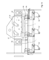
- FIG. 1b In the side view in FIG. 1b, two grippers 121, 122 are shown which hold the book block 1 in the first cutting position, the second cutting position and the device 100 and out of the device 100.
- the first gripper 121 is used to illustrate the Cutting position shown twice.
- the position that the first gripper 121 in FIG. 1b in in the middle is a transfer position in which the book block 1, the one with a Is provided, the second gripper (122) 122 is passed to in to be brought to the second cutting position.
- the second gripper 122 has one Thrust plate 125, with the book block 1 of which can be pushed onto a display 135, while at the same time a book block 1 'is pulled into the second cutting position.
- FIGS. 2a to 21 show the sequence of movements of the first gripper 121 Device according to the invention and its interaction with the device for Carrying out a leading edge trimming and transferring it to the second gripper (122) 122 shown.
- a book block 1 is placed on a base 191, in particular one Conveying table 191 with transport fingers 190 with its spine first in the arrow marked transport direction pushed.
- the first gripper 121 is in its Starting position, parked from book block 1 and along the transport path behind the Stop 182.
- the first gripper is open in this position, e.g. the upper
- the gripper leg 123 and the lower gripper leg 126 are set apart from one another.
- the upper gripper leg 123 can be pneumatically lower to grip, and lower and upper gripper legs 123, 126 can be raise, see also the description of Figures 3a and 3b.
- Fig. 2a shown are at this time the front knife 23, the Front knife hold-down 167, the stop 182, the first hold-down 180 and the second Hold-down device 181 in a passive position set down from the base 191.
- the stop 182 is in the transport path below moved and the book block 1 transported against the stop and with the straight pushers 190, which correspond to the transport fingers 190 in this embodiment, straight encountered.
- the book block 1 thereby assumes its zero position. Then moved the first gripper 121 in its zero position and grips the book block 1 such that the Book block 1 can be conveyed at an angle.
- the book block 1 is then moved into the first cutting position.
- the first gripper back a distance marked with the double arrow, which is the width of the Book block 1 corresponds. This distance depends on the format.
- the first gripper points a signal generator, not shown, which a controller 99 the position of the first Gripper 121 is transmitted so that the controller 99 drives the first, not shown Accordingly, gripper 121 can be driven, so that the required first Cutting position can be approached exactly.
- the first gripper 121 also raised the book block 1 to leave unsightly grinding marks to avoid on the book block 1.
- the first hold-down device 180 now presses the book block 1 in first cutting position.
- the cut will be particularly good if the book block 1 before the cut is pressed as close as possible to the knife 23. So next he presses Front knife hold-down device 167 the book block 1, see Fig. 2e before the cut is made, see Fig. 2f.
- front knives 23, Front knife hold-down device 167 and first hold-down device 180 back to their starting position.
- the spine is lifted using the first gripper and then into the Transfer position, compare Fig. 2g and Fig. 2h pulled and lowered.
- the book block 1 is also transferred from the second hold-down device 181 pressed down so that the alignment of the book block 1 is true to the angle and position preserved.
- the first gripper is released from the book block 1 and first to the rear and then moved back to its starting position under the book block 1.
- the second gripper 122 is moved to the book block 1, see FIGS. 2j, 2k and 21.
- the second gripper 122 moves the book block 1 to the second cutting position after the second gripper 122 has securely gripped the book block 1 and the second hold-down has Book block 1 has been released.
- the first gripper 121 is then already waiting for the following book block 1 '.
- the first gripper 121 is at the time when the second Gripper 122 is already submerged near the spine of book block 1, so that there are no collisions between the first gripper (121) 121 and the second Gripper (122) 122 can come.
- the first gripper 121 and the second gripper 122 differ in their construction Essentially only in the thrust plate 125, which the second gripper has and which serves to a book block 1, in which the side edge trimming has already been performed, from the Eject device for trimming book blocks 1.
- the construction of the grabs is shown in Figures 3a and 3b.
- the upper gripper leg 123 is by means of one upper gripper actuator 124 connected to the lower gripper leg 126.
- the lower gripper leg 126 is rotatably supported at a gripper leg pivot point 131.
- the lower gripper leg 126 is by means of a lower gripper leg actuator 129 and two rods 127, 128, one of the rods 128 around a fastener is rotatable about the pivot point 131.
- the gripper 121, 122 is provided with rollers 133, which are not shown Horizontal guidance are connected.
- the upper and lower gripper control element 124, 129 are e.g. around pneumatic cylinders. Others known to those skilled in the art Adjusting elements such as electric motors can also be used.
- 4a and 4b are details of a conveyor table of a device for moving Book blocks 1 shown by a device for trimming book blocks 1.
- the Transport fingers 190 are in two parallel, symmetrical to the center line of the Transport path arranged slots 197 guided in the conveyor table 191 and protrude from the housing 80 of the three-cutter 100.
- the transition between the conveyor table 191 to the housing 80 is by a pivotally mounted bridging plate 193 covered.
- the conveyor table 191 has a hinge 192 on one side, with which the conveyor table 191 also the three-knife trimmer 100 is connected.
- the Conveyor table 191 On the other side of the transport path, the Conveyor table 191 a lock with which the conveyor table 191 in the working position can be locked so that the conveyor table 191 is not accidentally during the ongoing operation of the triple cutter 100 from the housing 80 of the triple cutter 100 abschwenkt. So that the joint 192 is relieved, the conveyor table has at least one Conveyor table leg 195, which is connected to the floor by a wheel 196, see above that on the one hand a sufficient support effect is achieved and on the other hand that Swiveling the conveyor table 191 is facilitated.
Landscapes
- Life Sciences & Earth Sciences (AREA)
- Forests & Forestry (AREA)
- Engineering & Computer Science (AREA)
- Mechanical Engineering (AREA)
- Nonmetal Cutting Devices (AREA)
- Specific Conveyance Elements (AREA)
- Details Of Cutting Devices (AREA)
- Sawing (AREA)
- Separation, Sorting, Adjustment, Or Bending Of Sheets To Be Conveyed (AREA)
- Apparatuses And Processes For Manufacturing Resistors (AREA)
- Folding Of Thin Sheet-Like Materials, Special Discharging Devices, And Others (AREA)
- Manipulator (AREA)
Applications Claiming Priority (2)
| Application Number | Priority Date | Filing Date | Title |
|---|---|---|---|
| ITMI20030876 ITMI20030876A1 (it) | 2003-04-30 | 2003-04-30 | Dispositivo per muovere blocchi di libri in un dispositivo per tagliare blocchi di libri |
| ITMI20030876 | 2003-04-30 |
Publications (3)
| Publication Number | Publication Date |
|---|---|
| EP1473125A2 true EP1473125A2 (fr) | 2004-11-03 |
| EP1473125A3 EP1473125A3 (fr) | 2004-12-01 |
| EP1473125B1 EP1473125B1 (fr) | 2007-10-03 |
Family
ID=32983218
Family Applications (1)
| Application Number | Title | Priority Date | Filing Date |
|---|---|---|---|
| EP20040101353 Expired - Lifetime EP1473125B1 (fr) | 2003-04-30 | 2004-04-01 | Machine pour déplacer des livres dans une machine pour le rognage des livres |
Country Status (7)
| Country | Link |
|---|---|
| US (1) | US20050016345A1 (fr) |
| EP (1) | EP1473125B1 (fr) |
| JP (1) | JP2004330409A (fr) |
| CN (1) | CN1541817A (fr) |
| AT (1) | ATE374679T1 (fr) |
| DE (2) | DE502004005106D1 (fr) |
| IT (1) | ITMI20030876A1 (fr) |
Families Citing this family (15)
| Publication number | Priority date | Publication date | Assignee | Title |
|---|---|---|---|---|
| US7694350B2 (en) | 2004-05-07 | 2010-04-13 | Hodges Suzanne G | Privacy nursing gown |
| US8291799B2 (en) * | 2007-06-29 | 2012-10-23 | Quad/Graphics, Inc. | Adjustable trimming assembly |
| EP2130654B1 (fr) * | 2008-06-05 | 2012-08-01 | Müller Martini Holding AG | Dispositif de coupe du bord supérieur et/ou inférieur de produits d'impression guidés à l'intérieur par une barre de coupe |
| EP2147759B1 (fr) * | 2008-07-24 | 2013-10-30 | Müller Martini Holding AG | Procédé et dispositif pour la coupe d'au moins un bord latéral de produits d'impression reliés |
| CA2699953A1 (fr) * | 2009-07-21 | 2011-01-21 | World Color Press Inc. | Divers equipement, installations et methodes de rognage du papier |
| DE102010018879A1 (de) * | 2010-04-30 | 2011-11-03 | Heidelberger Druckmaschinen Ag | Vorrichtung zum dreiseitigen Beschnitt von Produkten |
| JP5904641B2 (ja) * | 2012-05-02 | 2016-04-13 | ホリゾン・インターナショナル株式会社 | 三方断裁機における冊子搬送チャック |
| WO2013179380A1 (fr) * | 2012-05-29 | 2013-12-05 | ホリゾン・インターナショナル株式会社 | Appareil de coupe de reliure destiné à couper des bords à deux reprises |
| JP5968087B2 (ja) * | 2012-06-04 | 2016-08-10 | ホリゾン・インターナショナル株式会社 | 冊子支え機構を備えた三方断裁機 |
| JP5950346B2 (ja) * | 2012-08-31 | 2016-07-13 | ホリゾン・インターナショナル株式会社 | 三方断裁機 |
| CN102909742B (zh) * | 2012-10-26 | 2016-07-13 | 安徽工程大学 | 一种切书装置 |
| TWI580966B (zh) * | 2015-12-09 | 2017-05-01 | 博通生技股份有限公司 | 血糖計啟動系統 |
| WO2021130360A1 (fr) * | 2019-12-27 | 2021-07-01 | Meccanotecnica S.P.A. | Dispositif de préhension de fil de couture pour machine à relier avec jet de gaz |
| CN111572213A (zh) * | 2020-06-22 | 2020-08-25 | 威誉智能制造(深圳)有限公司 | 书边印刷装置 |
| CN115946159B (zh) * | 2023-02-13 | 2023-08-08 | 东莞市美隆自动化机械设备有限公司 | 一种全自动三面切的方法及装置 |
Family Cites Families (10)
| Publication number | Priority date | Publication date | Assignee | Title |
|---|---|---|---|---|
| DE1105384B (de) * | 1958-05-02 | 1961-04-27 | Hans Mueller | Vorrichtung zum Foerdern und Anlegen von zu Broschueren vereinigten Papier-bogen an eine Schneidstation |
| US3167987A (en) * | 1963-08-23 | 1965-02-02 | Chicago Machinery Lab Inc | Book trimming machine |
| US4694722A (en) * | 1985-08-06 | 1987-09-22 | Cardinal Industries, Inc. | Apparatus for scoring and cutting wallboard and the like |
| US4982636A (en) * | 1989-03-17 | 1991-01-08 | Becking Paul E | Measured leader length supply system |
| US5172804A (en) * | 1991-08-09 | 1992-12-22 | Chersin Andrew J | Pallet bridge device |
| DE4442916A1 (de) * | 1994-12-01 | 1996-06-05 | Heinrich Baumann Fa | Schneidmaschine und Verfahren zum Beschneiden eines Schneidgut-Stapels |
| EP0941817B1 (fr) * | 1998-03-11 | 2003-06-11 | Grapha-Holding Ag | Machine pour le rognage automatique de produits imprimés, tels des brochures, des magazines ou des livres |
| JP2001252890A (ja) * | 2000-03-08 | 2001-09-18 | Horizon International Inc | 三方断裁機 |
| DE10124068A1 (de) * | 2000-05-17 | 2002-02-21 | Perfecta Schneidemaschinenwerk Gmbh | Vorrichtung und Verfahren zum automatischen Positionieren und Beschneiden von Schneidgut aus Papierwerkstoffen oder papierwerkstoffähnlichen, stapelbaren Materialien |
| DE10204296A1 (de) * | 2002-02-02 | 2003-08-14 | Kolbus Gmbh & Co Kg | Vorrichtung zum dreiseitigen Beschneiden von Druckprodukten |
-
2003
- 2003-04-30 IT ITMI20030876 patent/ITMI20030876A1/it unknown
-
2004
- 2004-03-31 JP JP2004103564A patent/JP2004330409A/ja active Pending
- 2004-04-01 AT AT04101353T patent/ATE374679T1/de not_active IP Right Cessation
- 2004-04-01 EP EP20040101353 patent/EP1473125B1/fr not_active Expired - Lifetime
- 2004-04-01 DE DE200450005106 patent/DE502004005106D1/de not_active Expired - Lifetime
- 2004-04-02 DE DE200410016372 patent/DE102004016372A1/de not_active Withdrawn
- 2004-04-30 US US10/836,500 patent/US20050016345A1/en not_active Abandoned
- 2004-04-30 CN CNA2004100422194A patent/CN1541817A/zh active Pending
Also Published As
| Publication number | Publication date |
|---|---|
| DE102004016372A1 (de) | 2004-11-18 |
| US20050016345A1 (en) | 2005-01-27 |
| JP2004330409A (ja) | 2004-11-25 |
| ITMI20030876A1 (it) | 2004-11-01 |
| ATE374679T1 (de) | 2007-10-15 |
| CN1541817A (zh) | 2004-11-03 |
| DE502004005106D1 (de) | 2007-11-15 |
| EP1473125A3 (fr) | 2004-12-01 |
| EP1473125B1 (fr) | 2007-10-03 |
Similar Documents
| Publication | Publication Date | Title |
|---|---|---|
| EP0242763B1 (fr) | Dispositif pour couper des feuilles empilées | |
| EP1473125A2 (fr) | Machine pour déplacer des livres dans une machine pour le rognage des livres | |
| EP0429941B1 (fr) | Dispositif pour couper des feuilles empilées | |
| DE602004005539T2 (de) | Plattensägemaschine | |
| EP0906161B1 (fr) | Machine d'usinage pour pieces sous forme de plaques, notamment pour produire des bords plies sur des pieces en tole | |
| EP3288731A1 (fr) | Dispositif trancheur | |
| DE3613315C2 (fr) | ||
| EP0418529B1 (fr) | Appareil pour limiter des feuilles imprimées à trois côtés | |
| DE1552613A1 (de) | Einspannvorrichtung fuer Band- und Streifenmaterial | |
| EP1022222A2 (fr) | Dispositif pour enlever une bande de cerclage d'objets liés avec de telles bandes, spécialement des bobines | |
| DE3521210C1 (de) | Vorrichtung zum Abstuetzen eines auf einer Plattenaufteilsaege hergestellten langen und schmalen Werkstueckpakets | |
| EP1018408A1 (fr) | Guillotine pour couper des produits en feuilles empilées | |
| EP1106551B1 (fr) | Appareil et méthode pour couper une bande | |
| DE10124068A1 (de) | Vorrichtung und Verfahren zum automatischen Positionieren und Beschneiden von Schneidgut aus Papierwerkstoffen oder papierwerkstoffähnlichen, stapelbaren Materialien | |
| EP1249408A1 (fr) | Dispositif pour saisir ,transporter et positionner une pile de matériaux en feuilles | |
| DE19914580A1 (de) | Verfahren zum Handhaben von Stapeln von Papier, Pappe o. dgl. an einer Schneidmaschine | |
| DE1291678B (de) | Maschine zum Verpacken von Gruppen flacher Gegenstaende | |
| DE102004016373A1 (de) | Vorrichtung zum Zuschneiden von Buchblöcken | |
| EP0536507B1 (fr) | Dispositif pour diviser une meule de fromage | |
| AT403897B (de) | Aufschnittschneidemaschine mit kreismesser | |
| DE29814009U1 (de) | Schneideanlage mit Schnittguttransportsystem | |
| DE4104428A1 (de) | Vorrichtung zum entfernen der ecken von bogenstapeln | |
| EP2083964B1 (fr) | Dispositif pour souder un matériau en bande | |
| EP2103398B1 (fr) | Dispositif et procédé de coupe de produits d'impression pliés | |
| EP0583742A1 (fr) | Procédé et machine pour enlever un enveloppement en jute d'une balle de tabac |
Legal Events
| Date | Code | Title | Description |
|---|---|---|---|
| PUAI | Public reference made under article 153(3) epc to a published international application that has entered the european phase |
Free format text: ORIGINAL CODE: 0009012 |
|
| PUAL | Search report despatched |
Free format text: ORIGINAL CODE: 0009013 |
|
| AK | Designated contracting states |
Kind code of ref document: A2 Designated state(s): AT BE BG CH CY CZ DE DK EE ES FI FR GB GR HU IE IT LI LU MC NL PL PT RO SE SI SK TR |
|
| AX | Request for extension of the european patent |
Extension state: AL HR LT LV MK |
|
| AK | Designated contracting states |
Kind code of ref document: A3 Designated state(s): AT BE BG CH CY CZ DE DK EE ES FI FR GB GR HU IE IT LI LU MC NL PL PT RO SE SI SK TR |
|
| AX | Request for extension of the european patent |
Extension state: AL HR LT LV MK |
|
| 17P | Request for examination filed |
Effective date: 20050601 |
|
| AKX | Designation fees paid |
Designated state(s): AT BE BG CH CY CZ DE DK EE ES FI FR GB GR HU IE IT LI LU MC NL PL PT RO SE SI SK TR |
|
| GRAP | Despatch of communication of intention to grant a patent |
Free format text: ORIGINAL CODE: EPIDOSNIGR1 |
|
| GRAS | Grant fee paid |
Free format text: ORIGINAL CODE: EPIDOSNIGR3 |
|
| GRAA | (expected) grant |
Free format text: ORIGINAL CODE: 0009210 |
|
| AK | Designated contracting states |
Kind code of ref document: B1 Designated state(s): AT BE BG CH CY CZ DE DK EE ES FI FR GB GR HU IE IT LI LU MC NL PL PT RO SE SI SK TR |
|
| REG | Reference to a national code |
Ref country code: GB Ref legal event code: FG4D Free format text: NOT ENGLISH |
|
| REG | Reference to a national code |
Ref country code: CH Ref legal event code: EP |
|
| REG | Reference to a national code |
Ref country code: IE Ref legal event code: FG4D Free format text: LANGUAGE OF EP DOCUMENT: GERMAN |
|
| REF | Corresponds to: |
Ref document number: 502004005106 Country of ref document: DE Date of ref document: 20071115 Kind code of ref document: P |
|
| NLV1 | Nl: lapsed or annulled due to failure to fulfill the requirements of art. 29p and 29m of the patents act | ||
| GBV | Gb: ep patent (uk) treated as always having been void in accordance with gb section 77(7)/1977 [no translation filed] | ||
| PG25 | Lapsed in a contracting state [announced via postgrant information from national office to epo] |
Ref country code: NL Free format text: LAPSE BECAUSE OF FAILURE TO SUBMIT A TRANSLATION OF THE DESCRIPTION OR TO PAY THE FEE WITHIN THE PRESCRIBED TIME-LIMIT Effective date: 20071003 Ref country code: SE Free format text: LAPSE BECAUSE OF FAILURE TO SUBMIT A TRANSLATION OF THE DESCRIPTION OR TO PAY THE FEE WITHIN THE PRESCRIBED TIME-LIMIT Effective date: 20080103 Ref country code: ES Free format text: LAPSE BECAUSE OF FAILURE TO SUBMIT A TRANSLATION OF THE DESCRIPTION OR TO PAY THE FEE WITHIN THE PRESCRIBED TIME-LIMIT Effective date: 20080114 |
|
| ET | Fr: translation filed | ||
| PG25 | Lapsed in a contracting state [announced via postgrant information from national office to epo] |
Ref country code: PT Free format text: LAPSE BECAUSE OF FAILURE TO SUBMIT A TRANSLATION OF THE DESCRIPTION OR TO PAY THE FEE WITHIN THE PRESCRIBED TIME-LIMIT Effective date: 20080303 Ref country code: BG Free format text: LAPSE BECAUSE OF FAILURE TO SUBMIT A TRANSLATION OF THE DESCRIPTION OR TO PAY THE FEE WITHIN THE PRESCRIBED TIME-LIMIT Effective date: 20080103 Ref country code: PL Free format text: LAPSE BECAUSE OF FAILURE TO SUBMIT A TRANSLATION OF THE DESCRIPTION OR TO PAY THE FEE WITHIN THE PRESCRIBED TIME-LIMIT Effective date: 20071003 |
|
| REG | Reference to a national code |
Ref country code: IE Ref legal event code: FD4D |
|
| PG25 | Lapsed in a contracting state [announced via postgrant information from national office to epo] |
Ref country code: DK Free format text: LAPSE BECAUSE OF FAILURE TO SUBMIT A TRANSLATION OF THE DESCRIPTION OR TO PAY THE FEE WITHIN THE PRESCRIBED TIME-LIMIT Effective date: 20071003 Ref country code: CZ Free format text: LAPSE BECAUSE OF FAILURE TO SUBMIT A TRANSLATION OF THE DESCRIPTION OR TO PAY THE FEE WITHIN THE PRESCRIBED TIME-LIMIT Effective date: 20071003 |
|
| PGFP | Annual fee paid to national office [announced via postgrant information from national office to epo] |
Ref country code: CH Payment date: 20080428 Year of fee payment: 5 |
|
| PLBE | No opposition filed within time limit |
Free format text: ORIGINAL CODE: 0009261 |
|
| STAA | Information on the status of an ep patent application or granted ep patent |
Free format text: STATUS: NO OPPOSITION FILED WITHIN TIME LIMIT |
|
| PG25 | Lapsed in a contracting state [announced via postgrant information from national office to epo] |
Ref country code: SK Free format text: LAPSE BECAUSE OF FAILURE TO SUBMIT A TRANSLATION OF THE DESCRIPTION OR TO PAY THE FEE WITHIN THE PRESCRIBED TIME-LIMIT Effective date: 20071003 Ref country code: RO Free format text: LAPSE BECAUSE OF FAILURE TO SUBMIT A TRANSLATION OF THE DESCRIPTION OR TO PAY THE FEE WITHIN THE PRESCRIBED TIME-LIMIT Effective date: 20071003 |
|
| 26N | No opposition filed |
Effective date: 20080704 |
|
| PGFP | Annual fee paid to national office [announced via postgrant information from national office to epo] |
Ref country code: BE Payment date: 20080428 Year of fee payment: 5 |
|
| PG25 | Lapsed in a contracting state [announced via postgrant information from national office to epo] |
Ref country code: IE Free format text: LAPSE BECAUSE OF FAILURE TO SUBMIT A TRANSLATION OF THE DESCRIPTION OR TO PAY THE FEE WITHIN THE PRESCRIBED TIME-LIMIT Effective date: 20071003 |
|
| PG25 | Lapsed in a contracting state [announced via postgrant information from national office to epo] |
Ref country code: GB Free format text: LAPSE BECAUSE OF FAILURE TO SUBMIT A TRANSLATION OF THE DESCRIPTION OR TO PAY THE FEE WITHIN THE PRESCRIBED TIME-LIMIT Effective date: 20071003 Ref country code: MC Free format text: LAPSE BECAUSE OF NON-PAYMENT OF DUE FEES Effective date: 20080430 |
|
| PG25 | Lapsed in a contracting state [announced via postgrant information from national office to epo] |
Ref country code: GR Free format text: LAPSE BECAUSE OF FAILURE TO SUBMIT A TRANSLATION OF THE DESCRIPTION OR TO PAY THE FEE WITHIN THE PRESCRIBED TIME-LIMIT Effective date: 20080104 Ref country code: EE Free format text: LAPSE BECAUSE OF FAILURE TO SUBMIT A TRANSLATION OF THE DESCRIPTION OR TO PAY THE FEE WITHIN THE PRESCRIBED TIME-LIMIT Effective date: 20071003 |
|
| PG25 | Lapsed in a contracting state [announced via postgrant information from national office to epo] |
Ref country code: SI Free format text: LAPSE BECAUSE OF FAILURE TO SUBMIT A TRANSLATION OF THE DESCRIPTION OR TO PAY THE FEE WITHIN THE PRESCRIBED TIME-LIMIT Effective date: 20071003 |
|
| PG25 | Lapsed in a contracting state [announced via postgrant information from national office to epo] |
Ref country code: CY Free format text: LAPSE BECAUSE OF FAILURE TO SUBMIT A TRANSLATION OF THE DESCRIPTION OR TO PAY THE FEE WITHIN THE PRESCRIBED TIME-LIMIT Effective date: 20071003 |
|
| PG25 | Lapsed in a contracting state [announced via postgrant information from national office to epo] |
Ref country code: AT Free format text: LAPSE BECAUSE OF NON-PAYMENT OF DUE FEES Effective date: 20080401 |
|
| BERE | Be: lapsed |
Owner name: HEIDELBERGER DRUCKMASCHINEN A.G. Effective date: 20090430 |
|
| REG | Reference to a national code |
Ref country code: CH Ref legal event code: PL |
|
| PG25 | Lapsed in a contracting state [announced via postgrant information from national office to epo] |
Ref country code: CH Free format text: LAPSE BECAUSE OF NON-PAYMENT OF DUE FEES Effective date: 20090430 Ref country code: LI Free format text: LAPSE BECAUSE OF NON-PAYMENT OF DUE FEES Effective date: 20090430 |
|
| PG25 | Lapsed in a contracting state [announced via postgrant information from national office to epo] |
Ref country code: FI Free format text: LAPSE BECAUSE OF FAILURE TO SUBMIT A TRANSLATION OF THE DESCRIPTION OR TO PAY THE FEE WITHIN THE PRESCRIBED TIME-LIMIT Effective date: 20071003 |
|
| PG25 | Lapsed in a contracting state [announced via postgrant information from national office to epo] |
Ref country code: BE Free format text: LAPSE BECAUSE OF NON-PAYMENT OF DUE FEES Effective date: 20090430 |
|
| PG25 | Lapsed in a contracting state [announced via postgrant information from national office to epo] |
Ref country code: LU Free format text: LAPSE BECAUSE OF NON-PAYMENT OF DUE FEES Effective date: 20080401 Ref country code: HU Free format text: LAPSE BECAUSE OF FAILURE TO SUBMIT A TRANSLATION OF THE DESCRIPTION OR TO PAY THE FEE WITHIN THE PRESCRIBED TIME-LIMIT Effective date: 20080404 |
|
| PG25 | Lapsed in a contracting state [announced via postgrant information from national office to epo] |
Ref country code: TR Free format text: LAPSE BECAUSE OF FAILURE TO SUBMIT A TRANSLATION OF THE DESCRIPTION OR TO PAY THE FEE WITHIN THE PRESCRIBED TIME-LIMIT Effective date: 20071003 |
|
| PGFP | Annual fee paid to national office [announced via postgrant information from national office to epo] |
Ref country code: FR Payment date: 20110503 Year of fee payment: 8 |
|
| REG | Reference to a national code |
Ref country code: FR Ref legal event code: ST Effective date: 20121228 |
|
| PG25 | Lapsed in a contracting state [announced via postgrant information from national office to epo] |
Ref country code: FR Free format text: LAPSE BECAUSE OF NON-PAYMENT OF DUE FEES Effective date: 20120430 |
|
| REG | Reference to a national code |
Ref country code: DE Ref legal event code: R081 Ref document number: 502004005106 Country of ref document: DE Owner name: MUELLER MARTINI HOLDING AG, CH Free format text: FORMER OWNER: HEIDELBERGER DRUCKMASCHINEN AKTIENGESELLSCHAFT, 69115 HEIDELBERG, DE Effective date: 20141023 |
|
| PGFP | Annual fee paid to national office [announced via postgrant information from national office to epo] |
Ref country code: DE Payment date: 20160415 Year of fee payment: 13 |
|
| PGFP | Annual fee paid to national office [announced via postgrant information from national office to epo] |
Ref country code: IT Payment date: 20160429 Year of fee payment: 13 |
|
| REG | Reference to a national code |
Ref country code: DE Ref legal event code: R119 Ref document number: 502004005106 Country of ref document: DE |
|
| PG25 | Lapsed in a contracting state [announced via postgrant information from national office to epo] |
Ref country code: DE Free format text: LAPSE BECAUSE OF NON-PAYMENT OF DUE FEES Effective date: 20171103 |
|
| PG25 | Lapsed in a contracting state [announced via postgrant information from national office to epo] |
Ref country code: IT Free format text: LAPSE BECAUSE OF NON-PAYMENT OF DUE FEES Effective date: 20170401 |