EP1473135A2 - Zufuhrvorrichtung zur Versorgung von Temperiermittelkanälen eines Spritzgiesswerkzeuges - Google Patents
Zufuhrvorrichtung zur Versorgung von Temperiermittelkanälen eines Spritzgiesswerkzeuges Download PDFInfo
- Publication number
- EP1473135A2 EP1473135A2 EP04003338A EP04003338A EP1473135A2 EP 1473135 A2 EP1473135 A2 EP 1473135A2 EP 04003338 A EP04003338 A EP 04003338A EP 04003338 A EP04003338 A EP 04003338A EP 1473135 A2 EP1473135 A2 EP 1473135A2
- Authority
- EP
- European Patent Office
- Prior art keywords
- temperature control
- lines
- line
- return
- channels
- Prior art date
- Legal status (The legal status is an assumption and is not a legal conclusion. Google has not performed a legal analysis and makes no representation as to the accuracy of the status listed.)
- Withdrawn
Links
Images
Classifications
-
- B—PERFORMING OPERATIONS; TRANSPORTING
- B29—WORKING OF PLASTICS; WORKING OF SUBSTANCES IN A PLASTIC STATE IN GENERAL
- B29C—SHAPING OR JOINING OF PLASTICS; SHAPING OF MATERIAL IN A PLASTIC STATE, NOT OTHERWISE PROVIDED FOR; AFTER-TREATMENT OF THE SHAPED PRODUCTS, e.g. REPAIRING
- B29C45/00—Injection moulding, i.e. forcing the required volume of moulding material through a nozzle into a closed mould; Apparatus therefor
- B29C45/17—Component parts, details or accessories; Auxiliary operations
- B29C45/26—Moulds
- B29C45/263—Moulds with mould wall parts provided with fine grooves or impressions, e.g. for record discs
- B29C45/2642—Heating or cooling means therefor
-
- B—PERFORMING OPERATIONS; TRANSPORTING
- B29—WORKING OF PLASTICS; WORKING OF SUBSTANCES IN A PLASTIC STATE IN GENERAL
- B29C—SHAPING OR JOINING OF PLASTICS; SHAPING OF MATERIAL IN A PLASTIC STATE, NOT OTHERWISE PROVIDED FOR; AFTER-TREATMENT OF THE SHAPED PRODUCTS, e.g. REPAIRING
- B29C33/00—Moulds or cores; Details thereof or accessories therefor
- B29C33/02—Moulds or cores; Details thereof or accessories therefor with incorporated heating or cooling means
- B29C33/04—Moulds or cores; Details thereof or accessories therefor with incorporated heating or cooling means using liquids, gas or steam
-
- B—PERFORMING OPERATIONS; TRANSPORTING
- B29—WORKING OF PLASTICS; WORKING OF SUBSTANCES IN A PLASTIC STATE IN GENERAL
- B29C—SHAPING OR JOINING OF PLASTICS; SHAPING OF MATERIAL IN A PLASTIC STATE, NOT OTHERWISE PROVIDED FOR; AFTER-TREATMENT OF THE SHAPED PRODUCTS, e.g. REPAIRING
- B29C45/00—Injection moulding, i.e. forcing the required volume of moulding material through a nozzle into a closed mould; Apparatus therefor
- B29C45/17—Component parts, details or accessories; Auxiliary operations
- B29C45/72—Heating or cooling
- B29C45/73—Heating or cooling of the mould
- B29C45/7306—Control circuits therefor
-
- B—PERFORMING OPERATIONS; TRANSPORTING
- B29—WORKING OF PLASTICS; WORKING OF SUBSTANCES IN A PLASTIC STATE IN GENERAL
- B29C—SHAPING OR JOINING OF PLASTICS; SHAPING OF MATERIAL IN A PLASTIC STATE, NOT OTHERWISE PROVIDED FOR; AFTER-TREATMENT OF THE SHAPED PRODUCTS, e.g. REPAIRING
- B29C45/00—Injection moulding, i.e. forcing the required volume of moulding material through a nozzle into a closed mould; Apparatus therefor
- B29C45/17—Component parts, details or accessories; Auxiliary operations
- B29C45/72—Heating or cooling
- B29C45/73—Heating or cooling of the mould
- B29C2045/7343—Heating or cooling of the mould heating or cooling different mould parts at different temperatures
-
- B—PERFORMING OPERATIONS; TRANSPORTING
- B29—WORKING OF PLASTICS; WORKING OF SUBSTANCES IN A PLASTIC STATE IN GENERAL
- B29L—INDEXING SCHEME ASSOCIATED WITH SUBCLASS B29C, RELATING TO PARTICULAR ARTICLES
- B29L2017/00—Carriers for sound or information
- B29L2017/001—Carriers of records containing fine grooves or impressions, e.g. disc records for needle playback, cylinder records
- B29L2017/003—Records or discs
- B29L2017/005—CD''s, DVD''s
Definitions
- the invention relates to a supply device for a temperature control agent for supply of temperature control channels in the two mold halves of an injection mold for flat, disc-shaped products, especially CD's and DVD's.
- the mold halves of injection molds are constantly on one elevated temperature of usually 50 - 140 ° C, which is lower than the usual injection temperature of 300 - 360 ° C, but still higher than that Room temperature. This ensures, on the one hand, that what is to be injected Plastic material does not cool down too quickly and the mold cavity completely fills out and that on the other hand the molding or Molding can be removed from the mold in a reasonable time.
- the tool temperature mentioned 50 - 140 ° C is at least in relation to the injection temperature so low that it can be considered as the demolding temperature.
- a special Problem in the production of thin and flat moldings such as CDoder Blank DVDs consists in the fact that these are little because of their disc shape are stable and warp easily.
- DE 195 33 045 A1 deals with a permanent casting mold for, among others Plastic injection molding.
- a guide body made of a material with high thermal conductivity, inside there are one or more channel systems for bath fluids are located.
- the mold surface should be poured onto a desired one brought to elevated temperature and immediately after the pouring process to a desired cooling temperature at a predetermined time be cooled down. Prevented by heating before injecting that the plastic mass solidifies too quickly, so that it is guaranteed that the mold cavity is completely filled.
- the cooling time should be reduced and thus overall, the cycle time can be shortened.
- WO 01/19590 A1 shows and describes a device for tempering of molds of injection molding machines, in which a tempering medium flows through lines in the mold and back through drain lines.
- the invention is therefore based on the object of a device at the outset mentioned type, which allows the cooling phase, in particular of Shorten moldings like CD's and DVD's in such a way that a lateral curvature of them flat, disc-shaped products are absent, and good impression quality the microstructure of the molded surface or high reproducibility the disc shape is guaranteed.
- the device according to the invention is characterized in that that the tempering agent channels on both sides of the mold cavity with branching lines of the supply and return lines of the Feed system that are connected in the sub-lines of the flow line or the return line separately controllable valves are provided, and that between the flow line and the return line a compensating valve is provided, which opens in the opposite direction to the valves in the sub-lines and closes.
- CD's and DVD's are examples of flat, disc-shaped products, which due to their essentially two-dimensional structure has little stability possess and tend to bend towards the third dimension or to arch.
- the procedure according to the invention effect only a short-term impulse cooling, but the consequence has that the cooling of the molding is accelerated. Furthermore, can by controlling the cooling or, more generally, the temperature control in the environment of the mold nest in both mold halves in relation to each other is a possibility be created to influence that the moldings as absolutely straight, flat discs are ejected.
- the cooling impulse can for example, be stronger in one half of the mold than in the other. He can insert earlier in one half of the mold than in the other or in one too last longer than the other.
- a reheating of the environment of the mold cavity to the mold temperature takes place relatively quickly and automatically due to the good heat conduction within the metal mold halves which are constantly increased Temperature, the mentioned tool temperature of e.g. Kept at 50-140 ° C become.
- the short heat withdrawal caused by the inventive Procedure occurs, compensated relatively quickly.
- the device comprises a temperature control fluid system which is based on a temperature control circuit in which a temperature control medium circulates continuously and kept at a predetermined temperature.
- cooling and heating devices are provided, for example a water heater on the one hand and a heat exchanger for cooling the temperature control medium on the other hand.
- Starting from the flow of the temperature control circuit branches the flow line so that each half of the mold is supplied with temperature control agent separately becomes.
- a separate controllable valve is included in each sub-line. This prevents pressure build-up when the valves are closed and the temperature control circuit is kept in motion, a compensating valve is provided, the is a line that connects the flow and return immediately.
- the compensating valve is in the opposite direction to the two in the partial lines of the Valves located controlled controlled, so closes when they are completely are open and will be fully opened if they are closed with corresponding transitions in the intermediate areas. It can switch or Overflow valves are used.
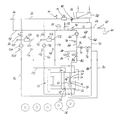
- An injection molding machine 10 is schematically represented in the drawing indicated by two mold halves 12 and 14.
- the mold halves form together a mold cavity 16, for example for the removal of a molding 18 can be opened by pulling the mold half 12 off the mold half 14 becomes.
- the mold cavity 16 is also referred to here as a mold cavity.
- the mold halves 12, 14 each have an inlet 20, 22 at which an inner, Temperature control channel system, not shown, starts at an outlet 24, 26 ends.
- the associated line system for the supply and discharge of a suitable temperature control medium will be explained later.
- the part of the temperature control system described here essentially serves to the mold halves in their entirety to a temperature in the region of the injection temperature, for example, to keep 90 to 120 ° C.
- the second temperature control system with the inlets 28, 30 only provided in the immediate vicinity of the mold cavity after the To deliver a relatively short cooling pulse.
- a temperature control medium is removed from a heat exchanger 38 via a line 36 taken.
- the heat exchanger can, for example, on the water network of the Operation be connected.
- the medium passes through a mixer 40, which will be discussed later to be, to a heater 42, by which the temperature is raised if necessary can become a vent valve 44 and finally one Overflow valve 46. From this position the line of the inner circuit, which we are dealing with here are to be regarded as return line 48. On line 48 there is a pressure accumulator 50 and a further pressure relief valve in the further course 52 and a temperature sensor 54, which is required for control purposes becomes.
- a branch line 56 branches off downstream of the temperature sensor, which makes it possible to Excess tempering medium via a valve 58 into a tank 60 drain.
- a circulation pump follows further downstream in the return line 48 62, which is an essential part of the system according to the invention and both the inner circle described above with lines 36 and 48 in Movement lasts as well as the tempering of the mold cavity, like afterwards to be explained.
- the circulation pump 62 feeds into a line 64, of which first a line 66 branches off with a throttle point 68, which opens into a further return line 70.
- the temperature control medium flows through this return line depending on the position of the Mixer 40 either directly back into line 36 or via the heat exchanger 38 and the first section of line 36 and the mixer in the following section of line 36. This results in a first state of the inner circle mentioned, in which the temperature control fluid via the lines 36 and 48 and the pump 62 circulated in the inner circle.
- the choke point 68 allows a minimum leakage current, which is the minimum circulation maintained in the inner circle.
- the line 64 branches into two sub-lines 80 and 82, in which valves 84 and 86 are located. These valves can be independent can be controlled from each other so that different amounts of temperature control media in the inlets 28 and 30 of the sewer system in the immediate vicinity of the mold cavity 16 can be initiated. After going through this Channel system exits the temperature control medium from the outlets 32 and 34 and arrives via the two return lines 88 and 90, which later on be summarized in the return line 70.
- the system described so far means that with the help of only one pump 62 on the one hand the so-called inner circle in motion and on the desired one Temperature can be maintained and that in the rest of the interaction with valves 84 and 86, the coolant flow rate in the duct system can be controlled on the immediate periphery of the mold cavity. Since the Valves 84 and 86 are adjustable independently of one another, there is the possibility due to different throughputs of the temperature control medium To achieve tempering effects. As mentioned, details are question of testing.
- the throttling points 68 and 74 referred to earlier have been designed so that the upper choke point 68 has a minimum leakage current that allows, in the aforementioned inner circle maintain a constant circulation.
- the lower throttle point 74 is in Series connected with the valve 76.
- This valve 76 is the opposite of that Valves 84 and 86 controlled the temperature control fluid in the temperature control channels 28, 30, 32, 34 in the immediate vicinity of the mold cavity. This means that the temperature control medium is constantly changing over the valves 84 and flow into the two mold halves and directly via the valve 76 can flow back.
- valves 84, 86 When the valves 84, 86 are closed, there is no sudden back pressure of the temperature control agent with the associated negative consequences.
- two feed lines 92 and 94 branch off to the inlets 20 and 22 of the channel system, not shown, for the temperature control of the two Guide mold halves.
- These flow lines 92 and 94 are located one after the other Control valves 96 and 98, vent valves 100 and 102 and pumps 104 and 106 and temperature sensors 108 and 110.
- Return lines emerge from the outlets 24 and 26 of the channel system of the mold halves 112, 114, in which there are temperature sensors 116, 118.
- the Return lines 112 and 114 ultimately open into the return line 48 of the inner one Circle, but are previously via a branch line 120, 122, in which there is a heater 124, 126 are connected to the flow line 92, 94.
- pumps 104, 106 either capture cooler medium from the line 36 of the inner circle or reheated medium from the Branch line 120, 122.
Landscapes
- Engineering & Computer Science (AREA)
- Mechanical Engineering (AREA)
- Manufacturing & Machinery (AREA)
- Moulds For Moulding Plastics Or The Like (AREA)
- Injection Moulding Of Plastics Or The Like (AREA)
Abstract
Description
Claims (5)
- Zufuhrvorrichtung für ein Temperiermittel zur Versorgung von Temperiermittelkanälen (28,30,32,34) in den beiden Formhälften eines Spritzgiesswerkzeuges für flache, scheibenförmige Produkte, insbesondere CD's und DVD's, dadurch gekennzeichnet, dass die Temperiermittelkanäle (28,30,32,34) auf beiden Seiten des Formhohlraumes mit sich verzweigenden Teilleitungen (80,20;32,34) der Vor- und Rücklaufleitung (64,70) des Zufuhrsystems verbunden sind, dass in den Teilleitungen (80,82) der Vorlaufleitung (64) oder der Rücklaufleitung (70) gesondert steuerbare Ventile (84,86) vorgesehen sind, und dass zwischen der Vorlaufleitung (64) und der Rücklaufleitung (70) ein Ausgleichsventil (76) vorgesehen ist, das gegenläufig zu den Ventilen (84,86) in den Teilleitungen öffnet und schliesst.
- Zufuhrvorrichtung nach Anspruch 1, dadurch gekennzeichnet, dass zwischen dem Vorlauf und dem Rücklauf des Temperiermittelkreises (36,48,64,70) parallel zu dem Ausgleichsventil (76) eine mit einer Drosselstelle (68) versehene Verbindungsleitung (66) vorgesehen ist.
- Zufuhrvorrichtung nach Anspruch 1 oder 2, dadurch gekennzeichnet, dass im Temperiermittelkreis (36,48,64,70) ein Durchlauferhitzer (42) und/oder ein Wärmetauscher (38) zur Kühlung des Temperiermediums vorgesehen ist.
- Zufuhrvorrichtung einem der Ansprüche 1 bis 3, dadurch gekennzeichnet, dass von dem Vorlauf des inneren Kreises Vorlaufleitungen (92, 94) abzweigen, die zu den ersten Temperiermittelkanälen (20,22,24,26) führen, dass die Auslässe (24,26) der ersten Temperiermittelkanäle über Rücklaufleitungen (112,114) mit dem Rücklauf des Temperiermittel-Kreises verbunden sind, und dass die Rücklaufleitungen (112,114) der ersten Temperiermittelkanäle jeweils mit den zugehörigen Vorlaufleitungen (92,94) über Verbindungsleitungen (120,122) direkt verbunden sind, in denen Erhitzer (124,126) befinden.
- Zufuhrvorrichtung nach einem der Ansprüche 1 bis 4, dadurch gekennzeichnet, dass in dem Temperiermittel-Kreis eine Umwälzpumpe (62) stromaufwärts der Teilleitungen (80,82) vorgesehen ist.
Applications Claiming Priority (2)
| Application Number | Priority Date | Filing Date | Title |
|---|---|---|---|
| DE10319243 | 2003-04-28 | ||
| DE2003119243 DE10319243B3 (de) | 2003-04-28 | 2003-04-28 | Zufuhrvorrichtung für ein Temperiermittel zur Versorgung von Temperiermittelkanälen |
Publications (2)
| Publication Number | Publication Date |
|---|---|
| EP1473135A2 true EP1473135A2 (de) | 2004-11-03 |
| EP1473135A3 EP1473135A3 (de) | 2005-02-09 |
Family
ID=32731170
Family Applications (1)
| Application Number | Title | Priority Date | Filing Date |
|---|---|---|---|
| EP04003338A Withdrawn EP1473135A3 (de) | 2003-04-28 | 2004-02-14 | Zufuhrvorrichtung zur Versorgung von Temperiermittelkanälen eines Spritzgiesswerkzeuges |
Country Status (3)
| Country | Link |
|---|---|
| EP (1) | EP1473135A3 (de) |
| JP (1) | JP4113853B2 (de) |
| DE (1) | DE10319243B3 (de) |
Cited By (3)
| Publication number | Priority date | Publication date | Assignee | Title |
|---|---|---|---|---|
| EP1775097A1 (de) * | 2005-10-17 | 2007-04-18 | REMAK Maschinenbau GmbH | Gerät zur Temperierung von Formwerkzeugen, beispielsweise von Spritzgießmaschinen |
| CN116476344A (zh) * | 2023-05-06 | 2023-07-25 | 南京欧能机械有限公司 | 一种带有循环预热机构的模温机 |
| CN119871748A (zh) * | 2025-02-24 | 2025-04-25 | 株洲时代新材料科技股份有限公司 | 一种快速加热模具的管路结构及加热方法 |
Families Citing this family (2)
| Publication number | Priority date | Publication date | Assignee | Title |
|---|---|---|---|---|
| DE102005036437B3 (de) * | 2005-08-03 | 2006-12-21 | Technotrans Ag | Verfahren zum Temperieren von Kunststoff-Spritzgießwerkzeugen |
| DE102016119843A1 (de) * | 2016-10-18 | 2018-04-19 | Arburg Gmbh + Co Kg | Anordnung zum Wärmeaustausch und/oder zur Temperierung von Maschinenkomponenten |
Family Cites Families (11)
| Publication number | Priority date | Publication date | Assignee | Title |
|---|---|---|---|---|
| US3259175A (en) * | 1964-06-15 | 1966-07-05 | Robert A Kraus | Heating and cooling system for molds |
| FR1579975A (de) * | 1967-09-18 | 1969-08-29 | ||
| DE1938496A1 (de) * | 1969-07-29 | 1971-02-11 | Wintergerst Prof Dr Ing Siegmu | Verfahren zur Verhinderung von Orientierungen und Eigenspannungen in Spritzgussteilen aus thermoplastischen Massen beim Spritzgiessen und Vorrichtung zur Durchfuehrung des Verfahrens |
| JPS602327A (ja) * | 1983-06-20 | 1985-01-08 | Seiko Epson Corp | 樹脂成形用金型の温度制御方法 |
| AT396575B (de) * | 1985-09-16 | 1993-10-25 | Engel Kg L | Verfahren zur werkzeugtemperierung für die formwerkzeuge von spritzgiessmaschinen |
| JPS62208918A (ja) * | 1986-03-11 | 1987-09-14 | Hitachi Ltd | 金型温度調節装置 |
| JPH0557729A (ja) * | 1991-08-28 | 1993-03-09 | Matsushita Electric Ind Co Ltd | 金型温調法 |
| JPH05318545A (ja) * | 1992-05-22 | 1993-12-03 | Taiyo Yuden Co Ltd | ディスク基板の成形方法 |
| DE19533045A1 (de) * | 1995-09-07 | 1997-03-13 | Gerhard Dr Ing Betz | Dauergießform für Kunststoff-, Metall- und Glasguß |
| JPH10244333A (ja) * | 1997-02-28 | 1998-09-14 | P I D Eng:Kk | 金型温度調節器 |
| ATE271965T1 (de) * | 1999-09-14 | 2004-08-15 | Wittmann Kunststoffgeraete | Verfahren und vorrichtung zum temperieren von formwerkzeugen von spritzgussmaschinen |
-
2003
- 2003-04-28 DE DE2003119243 patent/DE10319243B3/de not_active Expired - Fee Related
-
2004
- 2004-02-14 EP EP04003338A patent/EP1473135A3/de not_active Withdrawn
- 2004-03-31 JP JP2004104676A patent/JP4113853B2/ja not_active Expired - Fee Related
Cited By (4)
| Publication number | Priority date | Publication date | Assignee | Title |
|---|---|---|---|---|
| EP1775097A1 (de) * | 2005-10-17 | 2007-04-18 | REMAK Maschinenbau GmbH | Gerät zur Temperierung von Formwerkzeugen, beispielsweise von Spritzgießmaschinen |
| CN116476344A (zh) * | 2023-05-06 | 2023-07-25 | 南京欧能机械有限公司 | 一种带有循环预热机构的模温机 |
| CN116476344B (zh) * | 2023-05-06 | 2023-10-20 | 南京欧能机械有限公司 | 一种带有循环预热机构的模温机 |
| CN119871748A (zh) * | 2025-02-24 | 2025-04-25 | 株洲时代新材料科技股份有限公司 | 一种快速加热模具的管路结构及加热方法 |
Also Published As
| Publication number | Publication date |
|---|---|
| JP4113853B2 (ja) | 2008-07-09 |
| EP1473135A3 (de) | 2005-02-09 |
| DE10319243B3 (de) | 2004-08-19 |
| JP2004322637A (ja) | 2004-11-18 |
Similar Documents
| Publication | Publication Date | Title |
|---|---|---|
| EP0665780B1 (de) | Temperierbares werkzeug bzw. temperierbare form zur herstellung von kunststofformteilen und verfahren zur herstellung solcher werkzeuge bzw. formen | |
| DE2537037C3 (de) | Fluidgekühltes Formwerkzeug für schmelzflüssiges Glas | |
| EP3661720B1 (de) | Verfahren zur variothermen temperierung von spritzgiesswerkzeugen | |
| EP0335388A2 (de) | Spritzgussverfahren für Kunststoffe und Spritzgussform | |
| DE3242389C2 (de) | ||
| DE102009005142A1 (de) | Streckblasmaschine mit beheizbarer Blasform | |
| EP0666791B2 (de) | Verfahren zum spritzgiessen von formteilen aus thermoplastischem kunststoffmaterial sowie werkzeug zur durchführung desselben | |
| AT516167B1 (de) | Temperiervorrichtung zum variothermen oder konventionellen Temperieren von Formwerkzeugen | |
| DE10329494B3 (de) | Temperiervorrichtung für Spritzgiesswerkzeuge | |
| DE10319243B3 (de) | Zufuhrvorrichtung für ein Temperiermittel zur Versorgung von Temperiermittelkanälen | |
| DE102007019389A1 (de) | Temperiersystem, Vorrichtung mit Temperiersystem und Verfahren zum Temperieren einer Vorrichtung sowie zur Herstellung der Vorrichtung | |
| EP0820374A1 (de) | Heisskanal-spritzwerkzeug | |
| DE102010062260A1 (de) | Temperierbares Formwerkzeugelement | |
| DE2444012C2 (de) | Vorrichtung zum Verarbeiten, insbesondere zum Extrudieren, von schmelzflüssigen Kunststoffen | |
| EP1212184B1 (de) | Verfahren und vorrichtung zum temperieren von formwerkzeugen von spritzgussmaschinen | |
| DE1938496A1 (de) | Verfahren zur Verhinderung von Orientierungen und Eigenspannungen in Spritzgussteilen aus thermoplastischen Massen beim Spritzgiessen und Vorrichtung zur Durchfuehrung des Verfahrens | |
| EP1250992B1 (de) | Verfahren zum Kühlen der beiden Werkzeughälften eines Formwerkzeuges und Mischeinheit zur Durchführung des Verfahrens | |
| DE102004006162B4 (de) | Verfahren und Vorrichtung zur Temperierung eines Sprietzgießwerkzeugs | |
| DE2354134A1 (de) | Verteiler zum spritzgiessen thermoempfindlicher kunststoffe in mehrfachformwerkzeuge | |
| EP0499139B1 (de) | Einrichtung zum Beaufschlagen von mehreren Formen mit einem oder mehreren Fluiden und zum Temperieren der Formen für die Kunststoffverarbeitung | |
| DE102005036437B3 (de) | Verfahren zum Temperieren von Kunststoff-Spritzgießwerkzeugen | |
| DE10329493B3 (de) | Zufuhrvorrichtung für ein Temperiermittel zur Versorgung von Temperiermittelkanälen | |
| DE2317151A1 (de) | Metallgiessverfahren und vorrichtung zur durchfuehrung des verfahrens | |
| EP0953426A2 (de) | Temperierkreislauf für Spritzgussformen | |
| DE2217545A1 (de) | Heiz- und kuehleinrichtung fuer doppelwandige rotationshohlformen |
Legal Events
| Date | Code | Title | Description |
|---|---|---|---|
| PUAI | Public reference made under article 153(3) epc to a published international application that has entered the european phase |
Free format text: ORIGINAL CODE: 0009012 |
|
| AK | Designated contracting states |
Kind code of ref document: A2 Designated state(s): AT BE BG CH CY CZ DE DK EE ES FI FR GB GR HU IE IT LI LU MC NL PT RO SE SI SK TR |
|
| AX | Request for extension of the european patent |
Extension state: AL LT LV MK |
|
| PUAL | Search report despatched |
Free format text: ORIGINAL CODE: 0009013 |
|
| AK | Designated contracting states |
Kind code of ref document: A3 Designated state(s): AT BE BG CH CY CZ DE DK EE ES FI FR GB GR HU IE IT LI LU MC NL PT RO SE SI SK TR |
|
| AX | Request for extension of the european patent |
Extension state: AL LT LV MK |
|
| 17P | Request for examination filed |
Effective date: 20050223 |
|
| AKX | Designation fees paid |
Designated state(s): AT CH DE FR GB IT LI |
|
| 17Q | First examination report despatched |
Effective date: 20100504 |
|
| STAA | Information on the status of an ep patent application or granted ep patent |
Free format text: STATUS: THE APPLICATION IS DEEMED TO BE WITHDRAWN |
|
| 18D | Application deemed to be withdrawn |
Effective date: 20120918 |