EP1473141A1 - Verfahren und Vorrichtung zum Befestigen eines flexiblen Überzuges auf eine Sichtseite eines Paneels - Google Patents
Verfahren und Vorrichtung zum Befestigen eines flexiblen Überzuges auf eine Sichtseite eines Paneels Download PDFInfo
- Publication number
- EP1473141A1 EP1473141A1 EP04076338A EP04076338A EP1473141A1 EP 1473141 A1 EP1473141 A1 EP 1473141A1 EP 04076338 A EP04076338 A EP 04076338A EP 04076338 A EP04076338 A EP 04076338A EP 1473141 A1 EP1473141 A1 EP 1473141A1
- Authority
- EP
- European Patent Office
- Prior art keywords
- covering material
- panel
- installation
- glue
- roller
- Prior art date
- Legal status (The legal status is an assumption and is not a legal conclusion. Google has not performed a legal analysis and makes no representation as to the accuracy of the status listed.)
- Withdrawn
Links
Images




Classifications
-
- B—PERFORMING OPERATIONS; TRANSPORTING
- B29—WORKING OF PLASTICS; WORKING OF SUBSTANCES IN A PLASTIC STATE IN GENERAL
- B29C—SHAPING OR JOINING OF PLASTICS; SHAPING OF MATERIAL IN A PLASTIC STATE, NOT OTHERWISE PROVIDED FOR; AFTER-TREATMENT OF THE SHAPED PRODUCTS, e.g. REPAIRING
- B29C63/00—Lining or sheathing, i.e. applying preformed layers or sheathings of plastics; Apparatus therefor
- B29C63/02—Lining or sheathing, i.e. applying preformed layers or sheathings of plastics; Apparatus therefor using sheet or web-like material
- B29C63/04—Lining or sheathing, i.e. applying preformed layers or sheathings of plastics; Apparatus therefor using sheet or web-like material by folding, winding, bending or the like
- B29C63/044—Lining or sheathing, i.e. applying preformed layers or sheathings of plastics; Apparatus therefor using sheet or web-like material by folding, winding, bending or the like continuously
-
- B—PERFORMING OPERATIONS; TRANSPORTING
- B29—WORKING OF PLASTICS; WORKING OF SUBSTANCES IN A PLASTIC STATE IN GENERAL
- B29C—SHAPING OR JOINING OF PLASTICS; SHAPING OF MATERIAL IN A PLASTIC STATE, NOT OTHERWISE PROVIDED FOR; AFTER-TREATMENT OF THE SHAPED PRODUCTS, e.g. REPAIRING
- B29C63/00—Lining or sheathing, i.e. applying preformed layers or sheathings of plastics; Apparatus therefor
- B29C63/48—Preparation of the surfaces
- B29C2063/483—Preparation of the surfaces by applying a liquid
- B29C2063/485—Preparation of the surfaces by applying a liquid the liquid being an adhesive
Definitions
- the invention relates to a method for fixing a flexible covering material to a visible side of a panel, comprising the steps of:
- Such a method is generally known and is for instance used in the production of wall panels for system walls.
- wall panels generally consist of plaster boards which are covered with a decorative layer, for instance wallpaper, on the visible side, i.e. the side directed toward a space in the fitted state.
- Panels have been supplied heretofore by lifting them manually from a stack and pushing them through between two rollers.
- One of the rollers runs through a glue bath, so that one side of the panel, the visible side, is covered in glue.
- the covered panel is then placed, again manually, on a worktable and a sheet of covering material is placed on the glue-covered side of the panel and pressed in order to remove air bubbles. Finally, and still manually, edges of the covering material possibly protruding outside the panel are cut off. Once the panel has been thus finished, it is once again placed on a stack.
- the invention now has for its object to propose an improved method of the above stated type, wherein said drawbacks do not occur.
- this is achieved in such a method in that the layer of glue is applied to the covering material.
- Applying the glue layer to the covering material, instead of to the panel, provides a number of advantages.
- the side edges of the panel can hereby also be covered in simple manner, while applying of the glue layer can moreover be combined with the supply of the covering material in a manner which saves space.
- the covering material preferably has a width which is greater than the width of the panel, the glue layer is applied substantially over the whole width of the covering material and, along at least one side edge of the panel, an edge part of the covering material protruding outside this panel is folded around the side edge and glued to the side edge and/or a rear side of the panel remote from the visible side.
- the covering material can herein be placed on the panel such that an edge part protrudes on both sides thereof, and the protruding edge parts are folded over on both sides and glued to the side edge and/or the rear side of the panel.
- a panel is thus obtained wherein not only the visible side but also the side edges are covered, whereby the arranging of covering strips on the seams between adjacent panels in a system wall can be dispensed with.
- the new method is distinguished from the known method of covering panels in that the covering material is supplied on a roll, and is placed and pressed onto the visible side of the panel from the roll before being cut.
- the dimensioning of the covering material is thus simplified and it does not have to be pre-cut. Furthermore, little space is hereby necessary for the supply of the covering material.
- the cutting can herein preferably take place mechanically, whereby the number of human operations is reduced.
- supply of the panel and/or supply of the covering material takes place mechanically.
- the amount of manpower required to carry out the method is hereby further reduced.
- the pressing and/or folding takes place mechanically, whereby the number of heavy operations is limited still further.
- the invention also relates to an installation suitable for carrying out the above described method.
- the known installation for covering a panel with covering material does in fact only consist of a glue roller and a worktable.
- the installation according to the invention is distinguished from the known installation in the first instance in that the glue layer-applying device is adapted to apply the glue layer to the covering material.
- the installation can in addition or instead be provided with a device for supplying the panel.
- the panels hereby no longer have to be lifted and transported by hand.
- the panel supplying device advantageously comprises at least one roller table over which the panels can be transported in simple manner. This roller table can be preceded by a lifting unit for carrying the panels from a stack to the height of the roller table.
- the installation can be provided with a device for supplying the covering material, whereby the advantages set forth above can once again be achieved.
- the covering material supplying device herein advantageously comprises at least one roll holder for receiving a supply roll of the covering material. A large quantity of covering material can thus be readily supplied and placed in readiness.
- the invention provides an installation provided with a device for placing onto each other and pressing the visible side of the panel and the covering material, with which these operations can be performed in simple manner.
- the placing and pressing device preferably comprises at least one pressing element and at least one counterpressure element co-acting therewith, whereby a considerable force can be exerted on the covering material and the panel.
- the at least one counterpressure element is advantageously a roller of the roller table and the at least one pressing element is advantageously a pressing roller mounted above the roller table.
- the glue layer-applying device can comprise at least one glue roller which is arranged rotatably in a glue container and placed in the path of the covering material between the roll holder and the placing and pressing device, whereby the glue can be applied uniformly to the covering material.
- the glue-applying device can further comprise at least one glue distributing roller placed in the path of the covering material between the glue roller and the placing and pressing device.
- the at least one glue roller and/or the at least one glue distributing roller preferably has a surface layer with a profile whereby the glue, during rotation of the roller around its axis, is transported parallel to this axis.
- the glue roller and the glue distributing roller can herein have differently profiled surface layers.
- the placing and pressing device preferably has means for folding around at least one side edge of the panel an edge part of the covering material protruding outside thereof, whereby panels with a attractively finished side edge can be obtained.
- An installation with which the covering material can be folded in simple manner is obtained when the folding means comprise at least one deflecting roller placed behind the pressing roller and enclosing an angle therewith.
- a gradual folding operation is herein achieved by means of a number of successively placed deflecting rollers enclosing different angles with the pressing roller.
- the deflecting roller(s) is/are preferably not straight, but has/have a diabolo shape, thereby enhancing the folding operation.
- the covering installation can be provided with a device for cutting the covering material to size. Successive sheets of the covering material can hereby be brought in each case to the same size in simple manner.
- the cutting device for instance comprise one knife movable substantially transversely of the direction of transport of the panel and the covering material.
- An efficient cutting operation is herein achieved when the knife can be moved reciprocally parallel to a main plane of the panel.
- the cutting device is preferably placed between the pressing element and the folding means.
- the invention further relates to a glue layer-applying device, a panel supply device, a covering material supply device, a placing and pressing device and a cutting device for use in the installation as described above.
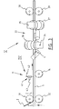
- An installation 20 for fixing a flexible covering material 2 on the visible side Z of a panel 1 comprises in the first instance a device 8 for supplying panel 1 and a device 9 for supplying covering material 2.
- installation 20 is provided with a device 7 for applying a layer of glue 3 between panel 1 and covering material 2, and a device 10 for placing onto each other and pressing panel 1 and covering material 2.
- Installation 20 is further also equipped with a device 11 for cutting the covering material 2 to size.
- the panel supplying device 8 comprises a roller table 12 which is formed by a frame 13 in which a number of rollers 14 supporting panel 1 are rotatably mounted.
- a lifting unit (not shown here) can optionally also be available before roller table 12, on which unit a supply stack of panels is arranged. This stack can then be raised over the thickness of one panel 1 at a time, whereafter the topmost panel of the stack can be pushed onto the roller table.
- the covering material supplying device 9 comprises a roll holder 15, which in the shown embodiment is fixed on frame 13 of roller table 12 and in which a supply roll 16 of the covering material can be accommodated in freely rotatable manner.
- Roll holder 15 is here formed by two parallel posts 17 with a recess 18 on the upper side for mounting a shaft 19 which can be placed through supply roller 16.
- the glue layer-applying device 7 comprises a glue roller 21 which is mounted for rotation about a shaft 22 between two walls 23 connected to frame 13 of roller table 12. Beneath glue roller 21 is arranged a glue container 24 in which a supply of glue is held. This supply is held at all times at a level such that the surface 25 of glue roller 21 always runs through the glue when roller 21 is rotating. The surface 25 of glue roller 21 is profiled in order to hold and distribute as evenly as possible the glue taken up from container 24.
- the glue layer-applying device 7 is further also provided with a glue distributing roller 26, which is placed behind glue roller 21 and is likewise mounted for rotation about a shaft 27 between walls 23.
- This glue distributing roller 26 also has a profiled surface 28, the profile of which is chosen such that, when roller 26 rotates on shaft 27, the glue is hereby transported parallel to this shaft 27 along the surface 28.
- the glue layer-applying device 7 is adapted to apply the layer of glue 3 to the supplied covering material 2, instead of to panel 1 as has been usual heretofore.
- the glue roller 21 and the glue distributing roller 26 are arranged between roll holder 15 and the placing and pressing device 10.
- the width of glue roller 21 and the glue distributing roller 26 is at least as great as the width B of the supplied covering material 2, so that this covering material can be covered over the whole width B with a glue layer 3.
- the side edges 4 thereof can also be covered, as will be elucidated hereinbelow.
- the glue layer-applying device 7 otherwise also has first and second guide rollers 29, 30, which are also mounted rotatably between walls 23.
- the first guide roller 29 is placed between supply roll 16 and glue roller 21, while the second guide roller 30 is placed between glue roller 21 and the glue distributing roller 26. This ensures that covering material 2 comes into close contact with glue roller 21 and the glue distributing roller 26.
- the placing and pressing device 10 comprises a pressing element 31 in the form of a pressing roller placed above roller table 12, and a counterpressure element 32 which is formed by a roller of roller table 12.
- the distance between pressing roller 31 and counterpressure roller 32 corresponds to the thickness of panel 1.
- Both rollers 31, 32 can be covered with an elastic material, whereby panel 1 and covering material 2 can be pressed together firmly and uniformly.
- the placing and pressing device 10 is further provided with means 33 for folding protruding edge parts 5 of covering material 2 around the side edges 4 of panel 1.
- These folding means 33 are here formed by pairs of deflecting rollers 36, 37 mounted on either side in frame 13 of the roller table and rotatable about respective shafts 34, 35.
- the rotation shafts 34, 35 of each pair of deflecting rollers 36, 37 herein enclose different angles with pressing roller 31, and therefore with the main plane of panel 1, whereby folding of the covering material 2 round the side edges 4 of panel 1 can take place gradually.
- the deflecting rollers 36, 37 furthermore each have a diabolo shape, whereby folding over of edge parts 4 is further enhanced.
- a further pressing roller 38 and counterpressure roller 39 Following the final pair of deflecting rollers 37 are arranged a further pressing roller 38 and counterpressure roller 39, whereby the folded side edges 4 of covering material 2 are pressed firmly against the rear side A of panel 1.
- Cutting device 11 is attached to frame 13 of roller table 12 between the foremost and rearmost pairs of pressure and counterpressure rollers 31, 32 and 38, 39 respectively, and comprises a knife 41 which, in the shown embodiment, is movable transversely of the direction of transport of panel 1 through installation 20, i.e. parallel to rollers 14 of roller table 12.
- Knife 41 has a cutting blade 42 which is suspended from a carriage 44 for rotation about a shaft 43, which carriage is fixed to a chain 45 and is guided in a sub-frame 47 by rollers 46.
- Chain 45 is trained around two chain wheels 48, one of which can be driven in two opposing directions by a motor (not shown here).
- installation 20 is also provided with a drive 40 formed by a motor 49 which carries on its output shaft a pulley 50, around which is trained a drive belt 51.
- This drive belt 51 runs over a pulley 52 connected to glue roller 21, a pulley 53 connected to pressing roller 31, a pulley 54 connected to counterpressure roller 32, a pulley 55 connected to the second pressing roller 38, and finally a pulley 56 connected to second counterpressure roller 39.
- panel 1 is lifted from a supply stack and guided onto roller table 12. This can take place by means of a conveyor (not shown here) or a roller table placed before roller table 12. As soon as it enters the pinch between the driven pressing roller 31 and the counterpressure roller 32, panel 1 is automatically carried further along into installation 20.
- the covering material 2 is simultaneously carried from supply roll 16 to the pinch between pressing roller 31 and counterpressure roller 32 via the first guide roller 29, glue roller 21, the second guide roller 30 and the glue distributing roller 26.
- the covering material 2 is also carried along automatically from the pinch.
- a layer of glue 3 is applied by glue roller 21 to covering material 2 as it passes, this layer of glue then being spread even further in width direction B by the glue distributing roller 26.
- covering material 2 meets the visible side Z of panel 1 at the position of pressing roller 31 and counterpressure roller 32, it is pressed thereon. Air bubbles which may be present are here immediately smoothed out over the whole width by the pressure of rollers 31, 32, and a very good adhesion is realized.
- edge parts 4 of the covering material 2 protrude on either side beyond the side edges 5 of panel 1.
- panel 1 with the covering material 2 glued onto the visible side Z thereof is transported further by the rotation of pressure and counterpressure rollers 31, 32, these edge parts 4 come successively into contact with the first and second pairs of deflecting rollers 36, 37. They are hereby folded around side edges 5 of panel 1 and glued thereto in two steps. The edge parts 4 are firmly pressed against and glued to rear side A of panel 1 by passing through the second pressure and counterpressure rollers 38, 39.
- Knife 41 is herein moved in opposite direction at each subsequent cutting operation so that a reciprocating movement is carried out each time, wherein each stroke is in principle utilized efficiently.
- a panel can be covered rapidly and easily with a covering layer, which can furthermore extend around the edges of the panel.
Landscapes
- Engineering & Computer Science (AREA)
- Manufacturing & Machinery (AREA)
- Folding Of Thin Sheet-Like Materials, Special Discharging Devices, And Others (AREA)
Applications Claiming Priority (2)
| Application Number | Priority Date | Filing Date | Title |
|---|---|---|---|
| NL1023331A NL1023331C2 (nl) | 2003-05-02 | 2003-05-02 | Werkwijze en inrichting voor het op een zichtzijde van een paneel bevestigen van een buigzaam afdekmateriaal. |
| NL1023331 | 2003-05-02 |
Publications (1)
| Publication Number | Publication Date |
|---|---|
| EP1473141A1 true EP1473141A1 (de) | 2004-11-03 |
Family
ID=32986061
Family Applications (1)
| Application Number | Title | Priority Date | Filing Date |
|---|---|---|---|
| EP04076338A Withdrawn EP1473141A1 (de) | 2003-05-02 | 2004-05-03 | Verfahren und Vorrichtung zum Befestigen eines flexiblen Überzuges auf eine Sichtseite eines Paneels |
Country Status (2)
| Country | Link |
|---|---|
| EP (1) | EP1473141A1 (de) |
| NL (1) | NL1023331C2 (de) |
Cited By (1)
| Publication number | Priority date | Publication date | Assignee | Title |
|---|---|---|---|---|
| DE102024117477A1 (de) | 2024-06-20 | 2025-12-24 | Kuka Systems Gmbh | Verfahren und Vorrichtung zum automatischen Umschlagen wenigstens eines Folienüberstands einer Folie um eine Kante eines Bleches |
Families Citing this family (1)
| Publication number | Priority date | Publication date | Assignee | Title |
|---|---|---|---|---|
| CN115195100B (zh) * | 2022-06-21 | 2023-06-23 | 厦门微亚智能科技有限公司 | 一种高精度多边贴膜装置及其使用方法 |
Citations (2)
| Publication number | Priority date | Publication date | Assignee | Title |
|---|---|---|---|---|
| FR1470941A (fr) * | 1965-03-12 | 1967-02-24 | C F Roser G M B H | Procédé et dispositif pour appliquer des feuilles de matière synthétique thermoplastique sur des surfaces de pièces |
| US4065333A (en) * | 1977-03-31 | 1977-12-27 | National Gypsum Company | Facing sheet edge trimming |
-
2003
- 2003-05-02 NL NL1023331A patent/NL1023331C2/nl not_active IP Right Cessation
-
2004
- 2004-05-03 EP EP04076338A patent/EP1473141A1/de not_active Withdrawn
Patent Citations (2)
| Publication number | Priority date | Publication date | Assignee | Title |
|---|---|---|---|---|
| FR1470941A (fr) * | 1965-03-12 | 1967-02-24 | C F Roser G M B H | Procédé et dispositif pour appliquer des feuilles de matière synthétique thermoplastique sur des surfaces de pièces |
| US4065333A (en) * | 1977-03-31 | 1977-12-27 | National Gypsum Company | Facing sheet edge trimming |
Cited By (1)
| Publication number | Priority date | Publication date | Assignee | Title |
|---|---|---|---|---|
| DE102024117477A1 (de) | 2024-06-20 | 2025-12-24 | Kuka Systems Gmbh | Verfahren und Vorrichtung zum automatischen Umschlagen wenigstens eines Folienüberstands einer Folie um eine Kante eines Bleches |
Also Published As
| Publication number | Publication date |
|---|---|
| NL1023331C2 (nl) | 2004-11-03 |
Similar Documents
| Publication | Publication Date | Title |
|---|---|---|
| CN110524670B (zh) | 一种胶合板制造自动化封边机 | |
| EP2181799A1 (de) | Automatische Bördelstation für Tafeln mit verschiedenen Peripherieprofilen | |
| CN110053806B (zh) | 一种组合烟花围招的自动包裹装置 | |
| US4849063A (en) | Manual edge bander apparatus | |
| CN106458350B (zh) | 贴标签机 | |
| CN105216423A (zh) | 一种应用于玻璃生产加工的卧式覆膜机 | |
| CN110053808B (zh) | 一种组合烟花顶招底招的自动包覆装置 | |
| CN110843248B (zh) | 一种横刀滚刀一体贴窗机 | |
| JPS63102924A (ja) | シートに塗布し且つこれらシートを積層する方法及び装置 | |
| EP1473141A1 (de) | Verfahren und Vorrichtung zum Befestigen eines flexiblen Überzuges auf eine Sichtseite eines Paneels | |
| KR101475488B1 (ko) | 패널표면 라미네이팅 장치 | |
| CN205009720U (zh) | 一种应用于玻璃生产加工的卧式覆膜机 | |
| CN210503373U (zh) | 一种组合烟花围招的自动包裹装置 | |
| KR20050111394A (ko) | 유리판과 같은 기판에 기능막을 증착하는 방법과 상기방법을 수행하기 위한 막 코팅기 | |
| ITTO930866A1 (it) | Procedimento e macchina per la fabbricazione di copertine per libri e simili, e copertine cosi' realizzate. | |
| CN115009613A (zh) | 一种型材包纸机及方法 | |
| CN114364609B (zh) | 用于将提手安置在包装材料或包装材料组上的设备和方法 | |
| EP2817225B1 (de) | Verfahren und vorrichtung zum verpacken wenigstens eines gegenstandes in einer umhüllung und zum falten der umhüllung aus einem bogen faltbaren materials | |
| JPH1034770A (ja) | 半自動製函装置及び同装置用折畳み作業台 | |
| EP1840064A2 (de) | Vorrichtung zur Herstellung einer Papierrolle | |
| CN111422393A (zh) | 全自动包装设备 | |
| CN210308308U (zh) | 一种方便封边的封边机 | |
| CN114408250B (zh) | 自动胶带缠绕机 | |
| CN215397308U (zh) | 自动纸板包边机 | |
| KR101463199B1 (ko) | 무늬목박판 우드롤 제조장치 및 그 제조방법 |
Legal Events
| Date | Code | Title | Description |
|---|---|---|---|
| PUAI | Public reference made under article 153(3) epc to a published international application that has entered the european phase |
Free format text: ORIGINAL CODE: 0009012 |
|
| AK | Designated contracting states |
Kind code of ref document: A1 Designated state(s): AT BE BG CH CY CZ DE DK EE ES FI FR GB GR HU IE IT LI LU MC NL PL PT RO SE SI SK TR |
|
| AX | Request for extension of the european patent |
Extension state: AL HR LT LV MK |
|
| AKX | Designation fees paid | ||
| REG | Reference to a national code |
Ref country code: DE Ref legal event code: 8566 |
|
| STAA | Information on the status of an ep patent application or granted ep patent |
Free format text: STATUS: THE APPLICATION IS DEEMED TO BE WITHDRAWN |
|
| 18D | Application deemed to be withdrawn |
Effective date: 20050504 |