EP1473174A2 - Elément de prise pour doigt d'insertion à mouvement continu - Google Patents
Elément de prise pour doigt d'insertion à mouvement continu Download PDFInfo
- Publication number
- EP1473174A2 EP1473174A2 EP04252147A EP04252147A EP1473174A2 EP 1473174 A2 EP1473174 A2 EP 1473174A2 EP 04252147 A EP04252147 A EP 04252147A EP 04252147 A EP04252147 A EP 04252147A EP 1473174 A2 EP1473174 A2 EP 1473174A2
- Authority
- EP
- European Patent Office
- Prior art keywords
- envelope
- insert
- pusher
- open envelope
- paper
- Prior art date
- Legal status (The legal status is an assumption and is not a legal conclusion. Google has not performed a legal analysis and makes no representation as to the accuracy of the status listed.)
- Granted
Links
- 238000012856 packing Methods 0.000 claims abstract 8
- 238000005452 bending Methods 0.000 claims abstract 6
- 238000011144 upstream manufacturing Methods 0.000 abstract description 5
- 238000003780 insertion Methods 0.000 description 14
- 230000037431 insertion Effects 0.000 description 14
- 230000000087 stabilizing effect Effects 0.000 description 6
- 238000013459 approach Methods 0.000 description 4
- 238000000576 coating method Methods 0.000 description 4
- 239000011248 coating agent Substances 0.000 description 3
- 239000000463 material Substances 0.000 description 3
- 238000000034 method Methods 0.000 description 3
- 229910001220 stainless steel Inorganic materials 0.000 description 3
- 239000010935 stainless steel Substances 0.000 description 3
- 229920009936 Nylatron GS Polymers 0.000 description 2
- 230000006835 compression Effects 0.000 description 2
- 238000007906 compression Methods 0.000 description 2
- 238000006073 displacement reaction Methods 0.000 description 2
- 239000004696 Poly ether ether ketone Substances 0.000 description 1
- 230000001133 acceleration Effects 0.000 description 1
- 239000000853 adhesive Substances 0.000 description 1
- 230000001070 adhesive effect Effects 0.000 description 1
- JUPQTSLXMOCDHR-UHFFFAOYSA-N benzene-1,4-diol;bis(4-fluorophenyl)methanone Chemical compound OC1=CC=C(O)C=C1.C1=CC(F)=CC=C1C(=O)C1=CC=C(F)C=C1 JUPQTSLXMOCDHR-UHFFFAOYSA-N 0.000 description 1
- 230000003247 decreasing effect Effects 0.000 description 1
- 230000013011 mating Effects 0.000 description 1
- 238000012986 modification Methods 0.000 description 1
- 230000004048 modification Effects 0.000 description 1
- 229920002530 polyetherether ketone Polymers 0.000 description 1
- 239000000843 powder Substances 0.000 description 1
- 230000001105 regulatory effect Effects 0.000 description 1
- 238000003466 welding Methods 0.000 description 1
Images





Classifications
-
- B—PERFORMING OPERATIONS; TRANSPORTING
- B43—WRITING OR DRAWING IMPLEMENTS; BUREAU ACCESSORIES
- B43M—BUREAU ACCESSORIES NOT OTHERWISE PROVIDED FOR
- B43M3/00—Devices for inserting documents into envelopes
- B43M3/04—Devices for inserting documents into envelopes automatic
Definitions
- a method and a device for conveying and pushing one or more sheets of paper or folded inserts into an envelope are provided, and more particularly a pusher finger guide conveying and pushing one or more sheets of paper or folded inserts into an envelope in a continuous motion system is provided.
- One conventional device disclosed in U.S. Patent No. 6,283,276, assigned on its face to Bell & Howell Mail and Messaging Technologies Co. of Durham, NC, and incorporated herein by reference in its entirety, utilizes two side-by-side overhead pusher finger guides or pushers used in tandem so that the insert (whether a flat or folded sheet or group of sheets) received at the upstream position will not skew prior to or at the time of insertion of the insert into the waiting envelope.
- Another conventional chain-driven device disclosed in U.S. Patent No. 5,806,659, also assigned on its face to Bell & Howell Mail and Messaging Technologies Co. of Durham, NC, and incorporated herein by reference in its entirety, utilizes a lightweight chain apparatus bearing a plurality of spaced-apart pusher members attached to the chain and a guide element intended to improve dimensional stability of the pusher members.
- FIG. 1 A conventional overhead conveyor 10 in accord with U.S. Patent No. 6,283,276 is depicted in FIG. 1.
- First and second circular drive members such as sprockets 15,20, are mounted on rotatable drive shafts 16, 17, respectively.
- Sprockets 15, 20 are positioned such that the X axis is tangent to the lowermost point of each of sprockets 15, 20 and, therefore, the lowermost point of each of sprockets 15, 20, lie along the same point of the Z (vertical) axis.
- Drive shaft 16 is connected to drive motor 25, and endless conveyor chain 30 is wrapped around the teeth of sprockets 15, 20 and comprises upper conveyor chain run 30a and lower conveyor chain run 30b.
- overhead conveyor 10 may be an endless belt-based conveyor, in which case, the circular drive members would comprise pulleys.
- a plurality of pusher elements 40 are attached to conveyor chains 30 at a fixed spaced-apart distance.
- Each pusher element has a lower portion 40a for supporting the bottom of a sheet(s) and an indented portion 40b for receiving the rear portion of sheet(s) and pushing the same in paper feed direction F.
- a guide 100 is provided for assuring pusher element 40 moves only in the X direction with no deflection in the Y or -Z directions.
- Guide 100 comprises a guiding element 50 of a selected cross-sectional shape (e.g., a circular cross-section). Sidewalls 42 of the pushers 40 are configured to straddle the respective guiding element 50.
- Motor 25 drives conveyor chain 30 and guide elements 40 (rigidly fixed to endless conveyor chain 30) in the counter-clockwise direction through drive shaft 16 and sprockets 15, 20.
- pusher element 40 on an upper run 30a of endless conveyor chain 30 starts to pass downwardly around sprocket 20 and approaches guide element 50 of guide 100 at the bottom half of sprocket 20.
- the sidewalls 42 of pusher element 40 start to receive therebetween (e.g., straddle) guide element 50, and thereafter a horizontal cross wall 39 of pusher element 40 comes into contact with the top of guide element 50.
- indented portion 40b of pusher element 40 contacts the sheet and pushes it in direction X (paper feed direction F) until it reaches a designated release point (not shown), at which time the sheet S is released and pusher element 40 moves upwardly around sprocket 15 and out of engagement with guide element 150 to permit repetition of the cycle.
- an envelope insert conveyor assembly includes a first pair of rotation members and a second pair of rotation members spaced apart from one another.
- a first conveying member is disposed around the first pair of rotation members and a second conveying member is disposed around the second pair of rotation members to so as to rotate around the first rotation member and the second rotation member.
- a plurality of pusher members are fixed to each of the first conveying member and second conveying member.
- the pusher members each have paired sidewalls, a cross-wall connecting the paired walls, and an indented portion provided in each of the paired sidewalls.
- a gripping element is disposed adjacent an indented portion of one of the paired sidewalls and biased toward an interior surface of the indented portion.
- a pusher member for conveying an envelope insert comprising paired sidewalls and a cross-wall connecting the paired walls.
- Each of the paired sidewalls comprises, at a proximal end, downwardly protruding extensions comprising an attachment member.
- Each of the paired sidewalls also comprises a forwardly disposed generally U-shaped indented portion, wherein one of the generally U-shaped indented portions comprises a gripping element having a gripping member which is resiliently biased toward an interior surface of the indented portion.
- an overhead pusher finger guide system comprising a gripping element for gripping an insert
- a gripping element for gripping an insert
- FIG. 2 depicts a set of left and a right pusher elements 140, each bearing a resilient gripping member 150 in accord with the inventive disclosure.
- the pusher elements 140 are, in one aspect, made of a Nylatron GS material.
- the gripping member 150 is, in one aspect, made from a stainless steel, such as a #300 series. More advantageously, it is preferred that the gripping member 150 (e.g., a stainless steel) be coated with a suitable low-friction coating (e.g., a 95% PEEK/5% PFTE powder coating for application to stainless steel) on a lower portion thereof to reduce friction.
- a suitable low-friction coating e.g., a 95% PEEK/5% PFTE powder coating for application to stainless steel
- Such coating would, in one aspect, have a thickness between about 0.38mm - 0.51mm, but could have a greater or lesser thickness.
- other lower friction coatings known to those of ordinary skill in the art, could be employed.
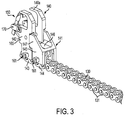
- FIG. 3 shows one such pusher element 140 bearing a resilient gripping member 150 attached to a conveyor chain 130.
- the attachment means includes a set of downwardly protruding extensions 143 that correspond in shape and spacing to the outermost chain link elements 131. The outermost chain link elements 131 are removed and the downwardly protruding extensions 143 are substituted in place thereof.
- a plurality of such pusher elements 140 are attached to the conveyor chain at a spaced-apart distance, which may be a fixed distance.
- Each pusher element has a lower portion 140a for supporting the bottom of a sheet or sheets, a packet, or a folded sheet or sheets (collectively referred to hereinafter as "insert" for brevity).
- An indented portion 140b is configured to receive a rear portion of the insert and push the same in a feed direction for insertion into an envelope.
- a supporting member 141 is attached to the conveyor chain 130 behind the pusher element 140.
- the attachment means includes a set of downwardly protruding extensions 144 that correspond in shape and spacing to the outermost chain link elements 131. The outermost chain link elements 131 are removed and the downwardly protruding extensions 144 are substituted in place thereof.
- Supporting member 141 comprises a generally H-shaped element having two upwardly directed walls 145 and a horizontal cross-wall 146.
- the upwardly directed walls 145 comprise forward projections 147 that engage corresponding recesses 148 in the pusher element 140 when the conveyor chain 130 is substantially horizontal and disengage from the recesses 148 in the pusher element 140 when the conveyor chain 130 deviates from the substantially horizontal, such as when the conveyor chain 130 is passed about at least a portion of a circumference of a gear or. sprocket.
- the combination of the supporting member 141, forward projections 147 and pusher element 140 recesses 148 provide increased rigidity to the pusher element 140, and therefore a greater degree of stability to the pusher element 140 and any object carried thereby.
- recesses 148 and forward projections 147 are provided approximately mid-way up the height of pusher element 140 sidewalls 142, this particular configuration is not required and the recesses 148 and forward projections 147 may be provided either higher or lower relative to the pusher element 140 sidewalls 142 in accord with the embodiment.
- pusher element 140 comprises a generally H-shaped element having sidewalls 142 and a horizontal cross-wall 139.
- holes 160 are provided in sidewalls 142 to permit connection (such as by pinning 161, adhesives, bonding, or suitable welding techniques) of the sidewalls 142 to elements 143 which replace the outermost elements 131 of a conveying chain 130.
- sidewalls 142 themselves may be formed for direct connection to the chain 130.
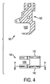
- Gripping member 150 comprises a pivot arm mounted for rotation about a pivot point formed by a pin 170 inserted through corresponding holes in a forward portion of the pusher element 140.
- Pin 170 may be, for example, a McMaster-Carr #90145A414.
- the pivot point generally defines an upper end of the pivot arm above the pivot point or pin 170 and a lower end of the pivot arm below the pivot point or pin 170.
- the lower end of the gripping member 150 pivot arm has a curved lower portion 176 configured to contact an upper inner surface of pusher element 140 lower portion 140a so as to prevent continued rotational movement of the pivot arm gripping member 150 in a counter-clockwise direction past the lower portion 140a.
- a distal end of the curved lower portion 176 optionally curves upwardly away from pusher element 140 lower portion 140a to prevent contact of the edge of the curved lower portion from the insert received within indented portion 140b.
- gripping member 150 may comprise a pivot arm with a straight lower portion, an angled lower portion, or a ball disposed at the lower end of the pivot arm, for example.
- a degree of rotation of the gripping member 150 pivot arm may be regulated by mating protrusions and/or combinations of protrusions and recesses on or in the gripping member 150 and inner surface of sidewalls 142.
- a hole 175 On an upper end of the gripping member 150 pivot arm, above the pin 170, is a hole 175 through which one end of a conventional tension spring 180 having looped ends is engaged.
- the opposite end of spring 180 is attached to sidewall 142 by a pin inserted through a through-hole 165.
- the opposite end of spring 180 enters a hole 185 in the forward edge of sidewall 142, the spring diameter being selected to be accommodated within said hole.
- the spring may include, for example, a Lee Spring # EI-011B-2-M, possessing a 2.38 mm outside diameter (OD). This spring, in combination with the embodiment depicted in FIGS. 2-6(c), provides a downwardly biased force against an insert of about 0.069 lb.
- the pin inserted through through-hole 165 may be, for example, a McMaster-Carr #90145A414.
- gripping member 150 is provided to pivot inwardly when an object, such as the aforementioned insert, encounters the leading or forwardmost edge of the lower end of the pivot arm. This inward pivoting motion exposes a height-wise portion of the indented portion 140b sufficient to receive an insert, which could comprise a range of thickness.
- An assist member comprising one or more rollers (e.g., elastomeric rollers)(see FIG. 9) may be provided, at an upstream (upper left side) of the continuous motion inserting machine 180 depicted in FIG. 7, which lightly press down upon an insert to control the insert as the insert travels forward and into position for engagement with pusher member indented portion 140b and gripper means 150.
- the forward motion imparted to the insert is provided by interface pins acting on a back side of the insert over a portion of the insert feed path up to the point at time in which the pusher members 140 engage and carry the insert.
- the interface pins are disposed to travel in a feed direction of the insert while acting along the back side of the insert at a location which will not interfere with the motion of the pusher elements.
- the pusher elements travel along a path in which they descend from above and behind the moving insert to engage a back side of the insert as it travels forward.
- an assist member may be provided along the path of travel of the pusher member 140 so as to impart a force to a forward or leading edge of the pivot arm immediately prior to contact of the pivot arm by the insert to slightly bias the pivot arm inwardly to facilitate entry of the insert (i.e., an edge thereof) into the indented portion 140b.
- pivot points and spring types are contemplated as being within the scope of the embodiment.
- the leading portions of pusher member 140 could be configured to receive a helical torsion spring acting either about the pivot point of the gripping member 150 or displaced therefrom depending upon the terminus configuration of the torsion spring.
- Additional configurations within the scope of the present concepts could employ a compression spring acting below the pivot point of the gripping member 150 to provide a biasing force against inward movement of the lower end of the gripper means 150 into the indented portion 140b.
- Still further configurations within the present concepts could employ a vertically translatable gripping member, such as the aforementioned pivot arm or even a lightweight roller ball or wheel configured to provide, in combination with a suitably placed spring (e.g., a tension or compression spring), a desired downward force against the pusher member 140 upper inner portion of lower portion 140a.
- the vertically translatable gripper means 150 may be configured to co-act with a guide placed along and adjacent the path of travel of the pusher member 140 to provide the motive force for vertical displacement of the gripper means.
- the guide could force the gripper means 150 from a first state to a second state as the pusher element 140 travels across the guide.
- the gripping member 150 provides a downward force biasing the insert against the pusher member 140 lower portion 140a to ensure that the insert does not slip relative to the pusher member 140.
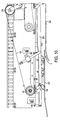
- FIGS. 9-10 An aspect of an apparatus in which the pusher members may advantageously be utilized is shown in FIGS. 9-10.
- the movement of an envelope is denoted by an arrow E passing upwardly between lower plate 300 and upper guide plate 310 and the movement of pusher member 140 is also denoted by an arrow.
- pushing member 140 arcs around sprocket 120, as shown in FIGS. 9-10, pushing member 140 encounters and retains an insert (not shown) provided thereto by an appropriate insert feed device prior to passage beyond upper guide plate 310.
- the envelope is conveyed in a position wherein the leading edge of the envelope is the bottom edge of the envelope and the open flap of the envelope is the trailing edge with the open flap being on the bottom (i.e., the envelope is face-down).
- the envelope is stopped, for a few milliseconds, by a registration stop acting in concert with lower plate 300.
- a vacuum may then be imparted by upper and lower vacuum members (not shown), during the fleeting registration of the envelope, to both the upper and lower sides of the envelope to partially open the envelope and prepare the envelope for receipt of the insert carried by pusher members 140.
- inserting fingers 210 which may in one aspect be shaped in a substantially "taco-like" form, arc around cams 400, 410 in a clockwise direction (as viewed from above) and approach the partially open envelope from the rear in the vicinity of a beginning portion 215 of the envelope travel path within the insertion device.
- the outer surfaces of the inserting fingers 210 (e.g., outer surfaces of the "taco") further open and/or retain the open position of the envelope as an upper vacuum member is disengaged from the envelope back surface, which is face-up.
- the lug 211 of the inserting fingers abuts against the left and right top edges of the envelope and continued motion of the continuously moving inserting fingers 210 starts to push the envelope forward.
- the pushing members 140 bearing the insert approach an inner surface of the inserting fingers 210 tangentially as the inserting fingers 210 arc around cams 400, 410 and the outer leading edges of the insert engage inner surfaces of the around cams 400, 410 (e.g., inner surfaces of the "taco") which support and/or guide the insert into place within the envelope, which in one aspect may already be moving by virtue of the inserting fingers 210.
- the lower vacuum may advantageously be maintained as the envelope continues its downstream travel so as to provide a backforce to facilitate insertion of the insert into the envelope.
- the forward motion of the pusher members 140 removes the stuffed envelope from the insertion fingers 210 (e.g., the velocity of the pusher member 140 is greater than that of the insertion fingers 210).
- this disengagement of the combined envelope and insert from the pusher members 140 is achieved by utilizing a powered (e.g., motor-driven) roller cylinder or drum or a belt provided over a roller cylinder or drum, with one component of the belt driven systems being powered (e.g., motor-driven)(hereinafter simply "drum"), disposed under the path of the filled envelope, rotating such that an outer circumference of the drum is moving in the downstream direction at a velocity greater than that of the filled envelope and pusher member 140 immediately upstream of the drum.
- a powered (e.g., motor-driven) roller cylinder or drum or a belt provided over a roller cylinder or drum with one component of the belt driven systems being powered (e.g., motor-driven)(hereinafter simply "drum"), disposed under the path of the filled envelope, rotating such that an outer circumference of the drum is moving in the downstream direction at a velocity greater than that of the filled envelope and pusher member 140 immediately upstream of the drum.
- a stabilizing roller device is disposed above the path of the filled envelope and above the centerline of the drum to provide a slight downwardly biasing force to stabilize the filled envelope as it is accelerated by the rotating drum.
- the stabilizing roller device may comprise one or more vertically translatable elements, such as passive or reactive rollers disposed on a pneumatic, hydraulic, or solenoid powered piston.
- the stabilizing roller device may comprise rollers configured to rotate at a predetermined velocity matching that of the rotating drum.
- the stabilizing roller device may comprise a substantially stationary drum configured to permit setting of the drum at one of a plurality of preselected displacements from the centerline of the lower drum so as to provide a predetermined gap therebetween corresponding substantially to the thickness of filled envelopes conveyed therethrough.
- the combination of the rotating drum and the stabilizing roller device are configured, in combination, to accelerate both the envelope and the insert disposed therein away from the pusher member 140 such that the insert is pulled away from the gripping member 150 in a controlled manner.
- the orientations of the rotating drum (or belt) and the stabilizing roller device may also be reversed.
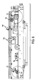
- FIGS. 7 and 8 depict one embodiment of continuous motion inserting machine 180 in which the aforementioned pusher members 140 are utilized.
- a plurality of pusher members 140. are arranged at predetermined intervals along a drive chain (not shown) provided around sprockets 115, 120, 132 and 134. Two such drive chains are provided and are disposed at substantially equal distances from a center of the device, indicated generally by center member 200.
- the pusher members 140 are driven in a counter-clockwise direction toward an upper left-hand portion of FIG. 7, where they engage sprocket 120 and are rotated downwardly to a bottom portion of the continuous motion inserting machine 180.
- Guide member 250 is substantially rectangular and optionally possesses chamfered or angled portions extending along a longitudinal direction of the guide member on upper surfaces thereof.
- the downwardly directed indented portions 140b of the pusher elements 140 are positioned, by virtue of guide 250, to receive an insert.
- the gripping member configuration may be adapted in a myriad of ways to achieve the desired result of providing a slight downward force on an insert received within the indented portion 140b of the pusher member 140, which incidentally may be configured to be shallower or deeper, as desired for the particular configuration of equipment.
- Supporting member 141 may be optionally omitted.
- pusher member 140 may comprise lightweight, durable materials other than Nylatron GS, such materials being known or easily ascertained by one of ordinary skill in the art.
Applications Claiming Priority (2)
| Application Number | Priority Date | Filing Date | Title |
|---|---|---|---|
| US46233803P | 2003-04-14 | 2003-04-14 | |
| US462338P | 2003-04-14 |
Publications (3)
| Publication Number | Publication Date |
|---|---|
| EP1473174A2 true EP1473174A2 (fr) | 2004-11-03 |
| EP1473174A3 EP1473174A3 (fr) | 2010-01-06 |
| EP1473174B1 EP1473174B1 (fr) | 2013-09-18 |
Family
ID=32990966
Family Applications (1)
| Application Number | Title | Priority Date | Filing Date |
|---|---|---|---|
| EP04252147.6A Expired - Lifetime EP1473174B1 (fr) | 2003-04-14 | 2004-04-13 | Machine d'introduction automatique de documents dans des enveloppes |
Country Status (2)
| Country | Link |
|---|---|
| US (1) | US7097028B2 (fr) |
| EP (1) | EP1473174B1 (fr) |
Cited By (1)
| Publication number | Priority date | Publication date | Assignee | Title |
|---|---|---|---|---|
| EP1911602A3 (fr) * | 2006-10-12 | 2010-03-17 | Bowe Bell + Howell Company | Appareils et procédés pour ouvrir des enveloppes de manière variable |
Families Citing this family (3)
| Publication number | Priority date | Publication date | Assignee | Title |
|---|---|---|---|---|
| US20060249894A1 (en) * | 2005-04-22 | 2006-11-09 | Halm Industries Co., Inc. | Adjustable aligner mechanism |
| US7900904B2 (en) * | 2007-04-30 | 2011-03-08 | Xerox Corporation | Modular finishing assembly with function separation |
| ES2994370B2 (es) * | 2023-07-17 | 2025-09-25 | Boix Maquinaria Spain Slu | Sistema de arrastre de una lámina de cartón en una máquina formadora de cajas |
Citations (1)
| Publication number | Priority date | Publication date | Assignee | Title |
|---|---|---|---|---|
| US6283276B1 (en) | 1999-04-15 | 2001-09-04 | Bell & Howell Mail And Messaging Technologies Company | Overhead pusher finger guide system |
Family Cites Families (13)
| Publication number | Priority date | Publication date | Assignee | Title |
|---|---|---|---|---|
| US2455127A (en) * | 1946-10-08 | 1948-11-30 | Atlas Imp Diesel Engine Co | Conveyer gripper member for can bodies |
| CH335093A (de) * | 1955-06-14 | 1958-12-31 | Grafiska Maskin A B | Verfahren zur Ablegung des Druckbogens an Zweitourenpressen und Vorrichtung zur Durchführung des Verfahrens |
| US3667189A (en) * | 1970-11-19 | 1972-06-06 | Reuben H Donnelley Corp The | Envelope window holder for an inserter and method |
| US4499705A (en) * | 1978-09-07 | 1985-02-19 | Mail-Ex Corporation | Semi-automatic insertion machine for envelopes |
| US4527378A (en) * | 1978-09-07 | 1985-07-09 | Mail-Ex Corporation | Semi-automatic insertion machine |
| US5675959A (en) * | 1996-01-18 | 1997-10-14 | Pitney Bowes Inc. | Opening fingers for envelope inserting apparatus |
| US5806659A (en) * | 1996-10-18 | 1998-09-15 | Bell And Howell Mail Processing Systems | Chain apparatus for high-speed media processing |
| US5848518A (en) * | 1997-07-17 | 1998-12-15 | Pitney Bowes Inc. | Envelope throat opening mechanism for inserting machine |
| US5964461A (en) * | 1997-10-03 | 1999-10-12 | Halm Industries Co., Inc. | Pusher block assembly for printing press |
| US6237746B1 (en) * | 1999-08-30 | 2001-05-29 | Pitney Bowes Inc. | Breakaway pusher for a timing belt of a mail inserter |
| IT1313365B1 (it) * | 1999-09-22 | 2002-07-23 | Sitma Spa | Trasportatore a spintori ribaltabili a riposizionamento automatico |
| JP4101482B2 (ja) * | 2001-07-13 | 2008-06-18 | 株式会社サム技研 | 用紙の高速封入装置 |
| US6851544B2 (en) * | 2003-05-19 | 2005-02-08 | Graphic Management Associates, Inc. | Transfer device |
-
2004
- 2004-04-13 EP EP04252147.6A patent/EP1473174B1/fr not_active Expired - Lifetime
- 2004-04-14 US US10/823,791 patent/US7097028B2/en not_active Expired - Fee Related
Patent Citations (1)
| Publication number | Priority date | Publication date | Assignee | Title |
|---|---|---|---|---|
| US6283276B1 (en) | 1999-04-15 | 2001-09-04 | Bell & Howell Mail And Messaging Technologies Company | Overhead pusher finger guide system |
Cited By (1)
| Publication number | Priority date | Publication date | Assignee | Title |
|---|---|---|---|---|
| EP1911602A3 (fr) * | 2006-10-12 | 2010-03-17 | Bowe Bell + Howell Company | Appareils et procédés pour ouvrir des enveloppes de manière variable |
Also Published As
| Publication number | Publication date |
|---|---|
| US7097028B2 (en) | 2006-08-29 |
| US20050067257A1 (en) | 2005-03-31 |
| EP1473174B1 (fr) | 2013-09-18 |
| EP1473174A3 (fr) | 2010-01-06 |
Similar Documents
| Publication | Publication Date | Title |
|---|---|---|
| EP0132617B1 (fr) | Appareil de transfert pour des objets | |
| US4596545A (en) | Orbital feeder | |
| EP1468841B1 (fr) | Machine pour le transport et l'insertion d'enveloppes | |
| US8011495B2 (en) | Transfer device metering apparatus and methods | |
| FI108021B (fi) | Päätön kiertävä kappaletavaroiden kuljetin, joka on varustettu erillisillä kuljetuselimillä | |
| US4779717A (en) | Method and apparatus for gripping, conveying and releasing printed products | |
| FI107322B (fi) | Menetelmä ja laite taitettujen painotuotteiden avaamiseksi | |
| EP1227051B1 (fr) | Procédé et dispositif pour le transport des rames de papier | |
| EP1473174B1 (fr) | Machine d'introduction automatique de documents dans des enveloppes | |
| US6168149B1 (en) | Method and unit for feeding blanks to a user machine | |
| ITMI950790A1 (it) | Dispositivo per l'alimentazione rapida di inserti a foglio ad un trasportatore a spintori di una macchina confezionatrice | |
| US3116924A (en) | Sheet conveying device | |
| US5443256A (en) | Process and device for the formation of a scale-like stream of folded printed copies | |
| EP1454854B1 (fr) | Dispositif pour tourner des paquets | |
| US4850583A (en) | Document transport device | |
| CN114249098B (zh) | 用于对齐包裹的装置 | |
| EP1468840B1 (fr) | Dispositif pour contrôler le rabat d'enveloppe pendant l'insertion | |
| CA2403643C (fr) | Dispositif permettant d'acheminer des objets plats | |
| EP1953104B1 (fr) | Système multi-stations et procédé de traitement d'envois postaux en papier | |
| GB1601166A (en) | Apparatus for conveying stacks of articles | |
| US6705607B2 (en) | Device for transporting printed products | |
| EP2200843B1 (fr) | Appareil et méthode pour la mise en place d'un produit dans une enveloppe | |
| JP5357453B2 (ja) | 丁合搬送装置 | |
| JP6384827B2 (ja) | 棒材の軸方向連続送り装置 | |
| JPH09151018A (ja) | フィルム搬送装置 |
Legal Events
| Date | Code | Title | Description |
|---|---|---|---|
| PUAI | Public reference made under article 153(3) epc to a published international application that has entered the european phase |
Free format text: ORIGINAL CODE: 0009012 |
|
| AK | Designated contracting states |
Kind code of ref document: A2 Designated state(s): AT BE BG CH CY CZ DE DK EE ES FI FR GB GR HU IE IT LI LU MC NL PL PT RO SE SI SK TR |
|
| AX | Request for extension of the european patent |
Extension state: AL HR LT LV MK |
|
| PUAL | Search report despatched |
Free format text: ORIGINAL CODE: 0009013 |
|
| AK | Designated contracting states |
Kind code of ref document: A3 Designated state(s): AT BE BG CH CY CZ DE DK EE ES FI FR GB GR HU IE IT LI LU MC NL PL PT RO SE SI SK TR |
|
| AX | Request for extension of the european patent |
Extension state: AL HR LT LV MK |
|
| 17P | Request for examination filed |
Effective date: 20100706 |
|
| AKX | Designation fees paid |
Designated state(s): AT BE BG CH CY CZ DE DK EE ES FI FR GB GR HU IE IT LI LU MC NL PL PT RO SE SI SK TR |
|
| RAP1 | Party data changed (applicant data changed or rights of an application transferred) |
Owner name: BELL AND HOWELL, LLC |
|
| 111Z | Information provided on other rights and legal means of execution |
Free format text: AT BE BG CH CY CZ DE DK EE ES FI FR GB GR HU IE IT LU MC NL PL PT RO SE SI SK TR Effective date: 20120201 |
|
| 17Q | First examination report despatched |
Effective date: 20120711 |
|
| GRAP | Despatch of communication of intention to grant a patent |
Free format text: ORIGINAL CODE: EPIDOSNIGR1 |
|
| INTG | Intention to grant announced |
Effective date: 20130524 |
|
| GRAS | Grant fee paid |
Free format text: ORIGINAL CODE: EPIDOSNIGR3 |
|
| GRAP | Despatch of communication of intention to grant a patent |
Free format text: ORIGINAL CODE: EPIDOSNIGR1 |
|
| GRAA | (expected) grant |
Free format text: ORIGINAL CODE: 0009210 |
|
| INTG | Intention to grant announced |
Effective date: 20130806 |
|
| AK | Designated contracting states |
Kind code of ref document: B1 Designated state(s): AT BE BG CH CY CZ DE DK EE ES FI FR GB GR HU IE IT LI LU MC NL PL PT RO SE SI SK TR |
|
| REG | Reference to a national code |
Ref country code: GB Ref legal event code: FG4D |
|
| REG | Reference to a national code |
Ref country code: CH Ref legal event code: EP |
|
| REG | Reference to a national code |
Ref country code: IE Ref legal event code: FG4D |
|
| REG | Reference to a national code |
Ref country code: AT Ref legal event code: REF Ref document number: 632528 Country of ref document: AT Kind code of ref document: T Effective date: 20131015 |
|
| REG | Reference to a national code |
Ref country code: DE Ref legal event code: R096 Ref document number: 602004043357 Country of ref document: DE Effective date: 20131114 |
|
| PG25 | Lapsed in a contracting state [announced via postgrant information from national office to epo] |
Ref country code: SE Free format text: LAPSE BECAUSE OF FAILURE TO SUBMIT A TRANSLATION OF THE DESCRIPTION OR TO PAY THE FEE WITHIN THE PRESCRIBED TIME-LIMIT Effective date: 20130918 Ref country code: CY Free format text: LAPSE BECAUSE OF FAILURE TO SUBMIT A TRANSLATION OF THE DESCRIPTION OR TO PAY THE FEE WITHIN THE PRESCRIBED TIME-LIMIT Effective date: 20130703 |
|
| REG | Reference to a national code |
Ref country code: NL Ref legal event code: VDEP Effective date: 20130918 |
|
| REG | Reference to a national code |
Ref country code: AT Ref legal event code: MK05 Ref document number: 632528 Country of ref document: AT Kind code of ref document: T Effective date: 20130918 |
|
| PG25 | Lapsed in a contracting state [announced via postgrant information from national office to epo] |
Ref country code: FI Free format text: LAPSE BECAUSE OF FAILURE TO SUBMIT A TRANSLATION OF THE DESCRIPTION OR TO PAY THE FEE WITHIN THE PRESCRIBED TIME-LIMIT Effective date: 20130918 Ref country code: GR Free format text: LAPSE BECAUSE OF FAILURE TO SUBMIT A TRANSLATION OF THE DESCRIPTION OR TO PAY THE FEE WITHIN THE PRESCRIBED TIME-LIMIT Effective date: 20131219 Ref country code: SI Free format text: LAPSE BECAUSE OF FAILURE TO SUBMIT A TRANSLATION OF THE DESCRIPTION OR TO PAY THE FEE WITHIN THE PRESCRIBED TIME-LIMIT Effective date: 20130918 |
|
| PG25 | Lapsed in a contracting state [announced via postgrant information from national office to epo] |
Ref country code: CY Free format text: LAPSE BECAUSE OF FAILURE TO SUBMIT A TRANSLATION OF THE DESCRIPTION OR TO PAY THE FEE WITHIN THE PRESCRIBED TIME-LIMIT Effective date: 20130918 Ref country code: BE Free format text: LAPSE BECAUSE OF FAILURE TO SUBMIT A TRANSLATION OF THE DESCRIPTION OR TO PAY THE FEE WITHIN THE PRESCRIBED TIME-LIMIT Effective date: 20130918 |
|
| PG25 | Lapsed in a contracting state [announced via postgrant information from national office to epo] |
Ref country code: CZ Free format text: LAPSE BECAUSE OF FAILURE TO SUBMIT A TRANSLATION OF THE DESCRIPTION OR TO PAY THE FEE WITHIN THE PRESCRIBED TIME-LIMIT Effective date: 20130918 Ref country code: EE Free format text: LAPSE BECAUSE OF FAILURE TO SUBMIT A TRANSLATION OF THE DESCRIPTION OR TO PAY THE FEE WITHIN THE PRESCRIBED TIME-LIMIT Effective date: 20130918 Ref country code: NL Free format text: LAPSE BECAUSE OF FAILURE TO SUBMIT A TRANSLATION OF THE DESCRIPTION OR TO PAY THE FEE WITHIN THE PRESCRIBED TIME-LIMIT Effective date: 20130918 Ref country code: RO Free format text: LAPSE BECAUSE OF FAILURE TO SUBMIT A TRANSLATION OF THE DESCRIPTION OR TO PAY THE FEE WITHIN THE PRESCRIBED TIME-LIMIT Effective date: 20130918 Ref country code: SK Free format text: LAPSE BECAUSE OF FAILURE TO SUBMIT A TRANSLATION OF THE DESCRIPTION OR TO PAY THE FEE WITHIN THE PRESCRIBED TIME-LIMIT Effective date: 20130918 |
|
| PG25 | Lapsed in a contracting state [announced via postgrant information from national office to epo] |
Ref country code: PL Free format text: LAPSE BECAUSE OF FAILURE TO SUBMIT A TRANSLATION OF THE DESCRIPTION OR TO PAY THE FEE WITHIN THE PRESCRIBED TIME-LIMIT Effective date: 20130918 Ref country code: ES Free format text: LAPSE BECAUSE OF FAILURE TO SUBMIT A TRANSLATION OF THE DESCRIPTION OR TO PAY THE FEE WITHIN THE PRESCRIBED TIME-LIMIT Effective date: 20130918 Ref country code: AT Free format text: LAPSE BECAUSE OF FAILURE TO SUBMIT A TRANSLATION OF THE DESCRIPTION OR TO PAY THE FEE WITHIN THE PRESCRIBED TIME-LIMIT Effective date: 20130918 |
|
| REG | Reference to a national code |
Ref country code: DE Ref legal event code: R097 Ref document number: 602004043357 Country of ref document: DE |
|
| PG25 | Lapsed in a contracting state [announced via postgrant information from national office to epo] |
Ref country code: PT Free format text: LAPSE BECAUSE OF FAILURE TO SUBMIT A TRANSLATION OF THE DESCRIPTION OR TO PAY THE FEE WITHIN THE PRESCRIBED TIME-LIMIT Effective date: 20140120 |
|
| PLBE | No opposition filed within time limit |
Free format text: ORIGINAL CODE: 0009261 |
|
| STAA | Information on the status of an ep patent application or granted ep patent |
Free format text: STATUS: NO OPPOSITION FILED WITHIN TIME LIMIT |
|
| 26N | No opposition filed |
Effective date: 20140619 |
|
| PG25 | Lapsed in a contracting state [announced via postgrant information from national office to epo] |
Ref country code: IT Free format text: LAPSE BECAUSE OF FAILURE TO SUBMIT A TRANSLATION OF THE DESCRIPTION OR TO PAY THE FEE WITHIN THE PRESCRIBED TIME-LIMIT Effective date: 20130918 |
|
| PG25 | Lapsed in a contracting state [announced via postgrant information from national office to epo] |
Ref country code: DK Free format text: LAPSE BECAUSE OF FAILURE TO SUBMIT A TRANSLATION OF THE DESCRIPTION OR TO PAY THE FEE WITHIN THE PRESCRIBED TIME-LIMIT Effective date: 20130918 |
|
| REG | Reference to a national code |
Ref country code: DE Ref legal event code: R097 Ref document number: 602004043357 Country of ref document: DE Effective date: 20140619 |
|
| PG25 | Lapsed in a contracting state [announced via postgrant information from national office to epo] |
Ref country code: LU Free format text: LAPSE BECAUSE OF FAILURE TO SUBMIT A TRANSLATION OF THE DESCRIPTION OR TO PAY THE FEE WITHIN THE PRESCRIBED TIME-LIMIT Effective date: 20140413 Ref country code: MC Free format text: LAPSE BECAUSE OF FAILURE TO SUBMIT A TRANSLATION OF THE DESCRIPTION OR TO PAY THE FEE WITHIN THE PRESCRIBED TIME-LIMIT Effective date: 20130918 |
|
| GBPC | Gb: european patent ceased through non-payment of renewal fee |
Effective date: 20140413 |
|
| REG | Reference to a national code |
Ref country code: IE Ref legal event code: MM4A |
|
| PG25 | Lapsed in a contracting state [announced via postgrant information from national office to epo] |
Ref country code: GB Free format text: LAPSE BECAUSE OF NON-PAYMENT OF DUE FEES Effective date: 20140413 |
|
| PG25 | Lapsed in a contracting state [announced via postgrant information from national office to epo] |
Ref country code: IE Free format text: LAPSE BECAUSE OF NON-PAYMENT OF DUE FEES Effective date: 20140413 |
|
| REG | Reference to a national code |
Ref country code: FR Ref legal event code: PLFP Year of fee payment: 13 |
|
| PG25 | Lapsed in a contracting state [announced via postgrant information from national office to epo] |
Ref country code: BG Free format text: LAPSE BECAUSE OF FAILURE TO SUBMIT A TRANSLATION OF THE DESCRIPTION OR TO PAY THE FEE WITHIN THE PRESCRIBED TIME-LIMIT Effective date: 20130918 |
|
| PG25 | Lapsed in a contracting state [announced via postgrant information from national office to epo] |
Ref country code: HU Free format text: LAPSE BECAUSE OF FAILURE TO SUBMIT A TRANSLATION OF THE DESCRIPTION OR TO PAY THE FEE WITHIN THE PRESCRIBED TIME-LIMIT; INVALID AB INITIO Effective date: 20040413 Ref country code: TR Free format text: LAPSE BECAUSE OF FAILURE TO SUBMIT A TRANSLATION OF THE DESCRIPTION OR TO PAY THE FEE WITHIN THE PRESCRIBED TIME-LIMIT Effective date: 20130918 |
|
| REG | Reference to a national code |
Ref country code: DE Ref legal event code: R082 Ref document number: 602004043357 Country of ref document: DE Representative=s name: BIRD & BIRD LLP, DE |
|
| REG | Reference to a national code |
Ref country code: FR Ref legal event code: PLFP Year of fee payment: 14 |
|
| REG | Reference to a national code |
Ref country code: FR Ref legal event code: PLFP Year of fee payment: 15 |
|
| PGFP | Annual fee paid to national office [announced via postgrant information from national office to epo] |
Ref country code: FR Payment date: 20210426 Year of fee payment: 18 Ref country code: DE Payment date: 20210428 Year of fee payment: 18 |
|
| PGFP | Annual fee paid to national office [announced via postgrant information from national office to epo] |
Ref country code: CH Payment date: 20210505 Year of fee payment: 18 |
|
| REG | Reference to a national code |
Ref country code: DE Ref legal event code: R119 Ref document number: 602004043357 Country of ref document: DE |
|
| REG | Reference to a national code |
Ref country code: CH Ref legal event code: PL |
|
| PG25 | Lapsed in a contracting state [announced via postgrant information from national office to epo] |
Ref country code: LI Free format text: LAPSE BECAUSE OF NON-PAYMENT OF DUE FEES Effective date: 20220430 Ref country code: FR Free format text: LAPSE BECAUSE OF NON-PAYMENT OF DUE FEES Effective date: 20220430 Ref country code: DE Free format text: LAPSE BECAUSE OF NON-PAYMENT OF DUE FEES Effective date: 20221103 Ref country code: CH Free format text: LAPSE BECAUSE OF NON-PAYMENT OF DUE FEES Effective date: 20220430 |