EP1473232A1 - Vorrichtung zum Bündeln für eine Umreifungsmaschine - Google Patents
Vorrichtung zum Bündeln für eine Umreifungsmaschine Download PDFInfo
- Publication number
- EP1473232A1 EP1473232A1 EP04003978A EP04003978A EP1473232A1 EP 1473232 A1 EP1473232 A1 EP 1473232A1 EP 04003978 A EP04003978 A EP 04003978A EP 04003978 A EP04003978 A EP 04003978A EP 1473232 A1 EP1473232 A1 EP 1473232A1
- Authority
- EP
- European Patent Office
- Prior art keywords
- load
- stop
- strapping machine
- belts
- bundling assembly
- Prior art date
- Legal status (The legal status is an assumption and is not a legal conclusion. Google has not performed a legal analysis and makes no representation as to the accuracy of the status listed.)
- Granted
Links
- 239000000463 material Substances 0.000 claims abstract description 61
- 230000037361 pathway Effects 0.000 claims abstract description 17
- 230000000087 stabilizing effect Effects 0.000 claims abstract description 8
- 239000003381 stabilizer Substances 0.000 description 4
- 230000008901 benefit Effects 0.000 description 3
- 238000000034 method Methods 0.000 description 3
- 230000008569 process Effects 0.000 description 3
- 238000011144 upstream manufacturing Methods 0.000 description 3
- 230000003466 anti-cipated effect Effects 0.000 description 2
- 238000012986 modification Methods 0.000 description 2
- 230000004048 modification Effects 0.000 description 2
- 238000012544 monitoring process Methods 0.000 description 1
Images


Classifications
-
- B—PERFORMING OPERATIONS; TRANSPORTING
- B65—CONVEYING; PACKING; STORING; HANDLING THIN OR FILAMENTARY MATERIAL
- B65B—MACHINES, APPARATUS OR DEVICES FOR, OR METHODS OF, PACKAGING ARTICLES OR MATERIALS; UNPACKING
- B65B27/00—Bundling particular articles presenting special problems using string, wire, or narrow tape or band; Baling fibrous material, e.g. peat, not otherwise provided for
- B65B27/08—Bundling paper sheets, envelopes, bags, newspapers, or other thin flat articles
Definitions
- the present invention is directed to strapping machines. More particularly, the present invention pertains to a bundling assembly for use with a strapping machine.
- Strapping machines are in widespread use for applying a strap, such as a plastic strap, in a tensioned loop around a load.
- a typical strapping machine includes a strap chute for guiding the strap around the load, a strapping head through which the leading end of the strap is fed, and at which the strap is tensioned and sealed to itself, and a strap dispenser to dispense a desired length of strap from a strap material supply.
- the strapping machine is used to strap bundles of printed materials.
- printed materials are often bundled and strapped prior to binding. These materials may also be bundled and strapped after binding and prior to handling for shipping.
- the materials are stacked together to form a stack or log.
- the stack is then positioned in the strapping machine and a strap is positioned around the stack, tensioned, and sealed onto itself.
- the stack or log is formed in a stacker which is located upstream of the strapping machine.
- the pages may fall out of alignment, or the stack may become skewed. This can create problems at the strapping machine, and may result in the damage to the printed materials.
- such a bundling assembly serves to maintain the lateral alignment of the stacked materials and moves the materials into the strapping machine. More desirably, such a machine longitudinally positions the load in the strapping machine and further moves the load out of the strapping machine to a downstream conveyor without any additional process time or handling steps or functions.
- a bundling assembly is configured for use with a strapping machine that positions a strap material around a load and tensions the strap material around the load.
- the bundling assembly serves to maintain the lateral alignment of the stacked materials (load) and moves the materials into the strapping machine.
- the bundling assembly longitudinally positions the load in the strapping machine and further moves the load out of the strapping machine to a downstream conveyor without any additional process time or handling steps or functions after the load is strapped.
- the bundling assembly includes first and second moving belts positioned at the strapping machine entrance in opposing relation to one another.
- the belts each have a paddle mounted thereto and define a pathway through the bundling assembly.
- a movable stop is positioned at the exit of the strapping machine and is movable between a stop position and a convey position.
- the moving belts rotate to contact the paddles with the load, urging the load into the entrance of the strapping machine and into an area under the chute.
- the belts stop rotation, thus stopping movement of the load upon contact of the load with the stop.
- the load is strapped and the movable stop moves to the convey position.
- the moving belts re-commence rotation, such that the paddles move the load out of the exit of the strapping machine.
- the belts each include only one paddle, and a motor is associated with each of the belts.
- the motor are mounted to frames that enclose the belts.
- the stop can include a rotating shaft and a stop element having a depending leg portion mounted to the shaft.
- the shaft rotates to move the leg between the stop position and the convey position.
- An actuator such as a pneumatic cylinder is operably mounted to the shaft for rotating the shaft.
- the stop position is adjustable to accommodate different sizes of materials.
- the bundling assembly can also include a stabilizing assembly disposed between the moving belts and the movable stop.
- the stabilizing assembly is configured to stabilize the stack of materials during the strapping operation.
- a present machine includes a controller.
- the moving belts, the movable stop and the stabilizing assembly are operably connected to the controller.
- FIG. 1 is a front view of a conventional strapping machine
- FIG. 2 is a front view of a strapping machine similar in overall design to that of FIG. 1, having a bundling assembly embodying the principles of the present invention
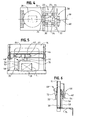
- FIG. 3 is a side view of the machine of FIG. 2 illustrating the bundling assembly
- FIG. 4 is a top view of the machine of FIG. 2;
- FIG. 5 is a rear view of the top portion of the machine showing the bundling assembly and having a stop bar rotated to the discharge position, and further showing the optional load stabilizer;
- FIG. 6 is a side view of the bundling assembly of FIG. 5, illustrating the stop bar and load stabilizer.
- a conventional strapping machine 10 having a workstation such as the illustrated tabletop 12 on which the load L may rest during the strapping operation.
- the machine 10 includes a chute 14 through which the strap S is advanced during the strapping operation and one or more strap dispensers 16 from which the strap S is dispensed to a strapping head 18.
- the strapping head 18 is that component of the machine 10 that withdraws or pulls the strap S from the dispenser 16, feeds the strap S through the chute 14, grasps the leading end of the strap S so as to bring it into contact with a trailing portion of strap, and tensions the trailing portion so as to compress the load L.
- the strap S is then sealed onto itself and severed to allow for removing the load L from the machine 10.
- the overall arrangement and operation of such a strapping machine 10 is disclosed in U.S. Patent Nos. 4,605,456 and 5,299,407, which patents are commonly assigned with the present application and the disclosures of which are incorporated herein by reference.
- the load or material L to be strapped is first oriented or prepared for strapping at an upstream process.
- the materials L may first be formed into a stack.
- the stack is then moved into the strapping machine 10 by automatic means. Referring briefly to FIG. 4, such a stacker is shown at 20, after which the stacked materials L are moved into the strapping machine 10.
- moving the materials L can result in the materials L moving relative to one another such that the stack becomes slightly skewed.
- Such a skew can occur in both the lateral direction d t (that is, that direction that is transverse to the direction of movement d l into the strapping machine 10) as well as in the longitudinal direction d l (the direction parallel to the movement of the materials into the strapping machine 10).
- the present bundling assembly 22 overcomes the problems associated with skew and corrects this skew by maintaining alignment of the materials L and moving the materials L into the strapping machine 10 a predetermined distance.
- the bundling assembly 22 includes a pair of opposing belts 24 mounted at the strapping machine entrance 23, upstream of the strapping machine chute 14, and positioned on either side of the pathway P along which the materials L traverse to enter the strapper 10.
- a bottom surface 26 of the path P is defined generally by a plurality of rollers 28 or other friction reducing means to permit readily moving the materials L into the area 30 under the chute 14.
- the belts 24 rotate around a plurality of rollers 32 to convey the material L toward the chute 14.
- Each belt 24 includes a paddle 34 that extends outwardly from the belt 24 and into the material pathway P.
- the paddles 34 are configured to contact the stacked material L and move the material L through the pathway P.
- the belts 24 are spaced from one another (on opposite sides of the pathway P), a distance d 24 about equal to the width w of the material L that is moved through the bundler 22. In this manner, as the paddles 34 move the material L along the pathway P, the belts 24 maintain the material L stacked in the transverse direction d t or orientation and the paddles 34 maintain the material L stacked in the longitudinal direction d l or orientation while moving the materials L through the bundling assembly 22.
- the belts 34 are mounted within frames 36 that are moveable toward and away from the pathway P centerline (the longitudinal centerline of the bundling machine as indicated at 38) to accommodate materials L of varying widths w.
- the frames 36 include enclosed side walls 40 and top walls 42 to enclose the belts 24 and to provide personnel protection.
- Motors 44 are mounted to the frame top walls 42 to drive the belts 24.
- the motors 44 include encoders (not shown) so that the position of the motor shaft can be continuously monitored.
- the encoders in combination with a control system 46 for the bundling assembly 22, permits controlling the alignment of the stack L (by assuring that the paddles 34 are maintained in opposing relation to one another) and controlling the depth to which the material stack L is moved into the strapping machine 10 (by controlling the distance of movement of the paddles 34 along the pathway P).
- the bundling assembly 22 includes a movable stop 48 positioned at the exit 50 of the strapping machine 10.
- the stop 48 includes a portion that moves into the pathway P to provide a surface or element against which the materials L abut when moved into the area 30 under the chute 14 (the stop position), and which moves out of the pathway P (the convey position, which is illustrated in FIG. 5) to permit moving the materials L out from the area 30 under the chute 14.
- the stop 48 is formed as a leg 52 mounted to a rotating shaft 54.
- the leg 52 has a transverse portion 56 (at which the leg 52 is mounted to the shaft 54) and a depending portion 58 that extends downwardly, toward the work surface 12.
- An actuator 62 is operably mounted to the shaft 54 for rotation.
- the actuator 62 is a pneumatic cylinder.
- Limit switches 64 can be mounted to the cylinder 62 to set the stop 48 at the stop and convey positions.
- An adjusting element 66 permits longitudinal adjustment of the stop bar 48 at the stop position to accommodate different sizes (lengths 1) of materials L.
- the bundling assembly 22 can include a stabilizing assembly 68 to provide pressure on the materials L during the strapping operation.
- the stabilizing assembly 68 includes a bar 70 that is moved into contact with the top of the stacked materials L once positioned in the chute area 30.
- the bar 70 can be moved up and down (into contact with and away from the material L) by, for example, a pneumatic cylinder 72 that is controlled by the overall control system 46.
- a stack of material L is moved into the pathway P and is positioned between the belts 24 with the paddles 34 at the trailing end T of the material L stack.
- the belt motors 44 are actuated and the paddles 34 urge the material L forward, into the area 30 under the strapping machine chute 14.
- the leading end E of the material stack L contacts the stop bar 48 and the belt motors 44 are stopped.
- the belt motors 44 can be set to stop at this position by use of the motor 44 encoders.
- the optional stabilizer 68 can then move down to contact and stabilize the material L stack.
- the strapping machine 10 is then actuated to convey the strap S around the stack, tension and seal the strap onto itself. Contemporaneously with the strapping operation, the stop bar 48 is rotated out of the pathway P.
- the belt motors 44 are again actuated.
- the belts 24 re-commence rotation and the paddles 34 then push or kick the now strapped material L stack out of the area 30 under the chute 14 onto a subsequent downstream conveyor 74.
- the materials can be strapped at a rate of about forty (40) bundles per minute. That is, about 40 bundled and strapped stacks can be formed per minute.
- the control system 46 for use with the bundling assembly 22 includes the necessary elements to monitor the position of the materials L as the materials L move into the machine 22, while the materials L are in the machine 22, and as the materials L are is moved out of the machine 22.
- sensors 76 can be positioned at the entry to the pathway P (e.g., on a bottom panel 78 between the belts 24 and/or mounted to the belt frames 36), and limit switches 64 can be mounted to the stop bar cylinder 62 and stabilizer cylinder 72.
- Other sensors, as well as monitoring and control instrumentation will be appreciated by those skilled in the art.
- the present bundling assembly 22 is shown with one paddle 34 located on each belt 24, it is anticipated that multiple paddles (e.g., two paddles) can be disposed on each belt (equally peripherally spaced from one another (e.g., 180 degrees from one another), in a configuration in which the belts 34 are sufficiently long and define a sufficiently long pathway P.
Landscapes
- Engineering & Computer Science (AREA)
- Mechanical Engineering (AREA)
- Basic Packing Technique (AREA)
Applications Claiming Priority (2)
| Application Number | Priority Date | Filing Date | Title |
|---|---|---|---|
| US10/425,579 US6789469B1 (en) | 2003-04-29 | 2003-04-29 | Bundling assembly for strapping machine |
| US425579 | 2003-04-29 |
Publications (2)
| Publication Number | Publication Date |
|---|---|
| EP1473232A1 true EP1473232A1 (de) | 2004-11-03 |
| EP1473232B1 EP1473232B1 (de) | 2006-08-23 |
Family
ID=32927395
Family Applications (1)
| Application Number | Title | Priority Date | Filing Date |
|---|---|---|---|
| EP04003978A Expired - Lifetime EP1473232B1 (de) | 2003-04-29 | 2004-02-21 | Vorrichtung zum Bündeln für eine Umreifungsmaschine |
Country Status (6)
| Country | Link |
|---|---|
| US (1) | US6789469B1 (de) |
| EP (1) | EP1473232B1 (de) |
| AU (1) | AU2004201754B2 (de) |
| CA (1) | CA2460913C (de) |
| DE (1) | DE602004002024T2 (de) |
| ES (1) | ES2271716T3 (de) |
Cited By (1)
| Publication number | Priority date | Publication date | Assignee | Title |
|---|---|---|---|---|
| CH710406A1 (de) * | 2014-11-25 | 2016-05-31 | Ferag Ag | Vorrichtung zum Umreifen von Produktstapeln. |
Families Citing this family (13)
| Publication number | Priority date | Publication date | Assignee | Title |
|---|---|---|---|---|
| US20050217215A1 (en) * | 2004-04-05 | 2005-10-06 | Illinois Tool Works, Inc. | Horizontal strapping machine |
| ES2296491B1 (es) * | 2005-12-09 | 2009-03-01 | Reparacion De Maquinaria Saizar, S.L. | Cabezal para flejadoras. |
| US7240612B1 (en) * | 2006-05-03 | 2007-07-10 | Illinois Tool Works Inc. | Strapping machine |
| US8025141B1 (en) * | 2008-12-23 | 2011-09-27 | Bouldin Corporation | Contour trimmer for potted plants |
| CH705743A2 (de) | 2011-11-14 | 2013-05-15 | Illinois Tool Works | Umreifungsvorrichtung. |
| US10279945B2 (en) | 2012-10-22 | 2019-05-07 | Encore Packaging Llc | Stretch film roping |
| PL3105127T3 (pl) | 2014-02-10 | 2019-11-29 | Orgapack Gmbh | Urządzenie do spinania taśmą |
| DE102014103331B4 (de) * | 2014-03-12 | 2025-06-26 | Mosca Gmbh | Steuerungsvorrichtung und -verfahren für eine Umreifungsmaschine |
| US10843827B2 (en) | 2016-11-06 | 2020-11-24 | Encore Packaging Llc | Stretch film processing to replace strapping |
| USD864688S1 (en) | 2017-03-28 | 2019-10-29 | Signode Industrial Group Llc | Strapping device |
| USD833493S1 (en) * | 2017-07-14 | 2018-11-13 | Encore Packaging Llc | Stretch strapping device |
| CA192340S (en) * | 2019-07-22 | 2021-12-30 | Ergopack Deutschland Gmbh | Packaging machine |
| US11673710B2 (en) | 2021-01-14 | 2023-06-13 | Encore Packaging Llc | Securing apparatus for packaging and shipping |
Citations (5)
| Publication number | Priority date | Publication date | Assignee | Title |
|---|---|---|---|---|
| US4090441A (en) * | 1976-01-27 | 1978-05-23 | Grapha-Holding Ag | Apparatus for stacking and baling newspapers or the like |
| US4605456A (en) | 1985-05-02 | 1986-08-12 | Signode Corporation | Method and apparatus for feeding and tensioning strap in a strapping machine |
| US5299407A (en) | 1991-11-26 | 1994-04-05 | Signode Bernpak Gmbh | Process and device for avoiding strapping-caused downtime on machine for strapping packages |
| EP0955239A1 (de) * | 1998-05-08 | 1999-11-10 | Gämmerler AG | Vorrichtung zur Behandlung von gestapelten Druckerzeugnissen |
| US20030024217A1 (en) * | 1999-05-05 | 2003-02-06 | Smb Schwede Maschinenbau Gmbh | Strapping machine for strapping a stack of products |
Family Cites Families (5)
| Publication number | Priority date | Publication date | Assignee | Title |
|---|---|---|---|---|
| US4015722A (en) * | 1975-10-16 | 1977-04-05 | Mckenney's, Inc. | Stacking machine and method |
| US4312266A (en) * | 1980-05-30 | 1982-01-26 | Ovalstrapping, Inc. | Object-turning apparatus for a high-speed strapping machine |
| US5560180A (en) * | 1994-08-05 | 1996-10-01 | Sandar Industries, Inc. | Method and apparatus for tying bundles with a paper pulp strap |
| BR9509123A (pt) * | 1994-10-03 | 1997-09-02 | Sig Schweizerische Industrei G | Correia sem fim e máquina de embalagem |
| US5944477A (en) * | 1997-05-27 | 1999-08-31 | Systematic Machinery Llc | Bundle squaring machine |
-
2003
- 2003-04-29 US US10/425,579 patent/US6789469B1/en not_active Expired - Fee Related
-
2004
- 2004-02-21 EP EP04003978A patent/EP1473232B1/de not_active Expired - Lifetime
- 2004-02-21 DE DE602004002024T patent/DE602004002024T2/de not_active Expired - Fee Related
- 2004-02-21 ES ES04003978T patent/ES2271716T3/es not_active Expired - Lifetime
- 2004-03-15 CA CA002460913A patent/CA2460913C/en not_active Expired - Fee Related
- 2004-04-27 AU AU2004201754A patent/AU2004201754B2/en not_active Ceased
Patent Citations (5)
| Publication number | Priority date | Publication date | Assignee | Title |
|---|---|---|---|---|
| US4090441A (en) * | 1976-01-27 | 1978-05-23 | Grapha-Holding Ag | Apparatus for stacking and baling newspapers or the like |
| US4605456A (en) | 1985-05-02 | 1986-08-12 | Signode Corporation | Method and apparatus for feeding and tensioning strap in a strapping machine |
| US5299407A (en) | 1991-11-26 | 1994-04-05 | Signode Bernpak Gmbh | Process and device for avoiding strapping-caused downtime on machine for strapping packages |
| EP0955239A1 (de) * | 1998-05-08 | 1999-11-10 | Gämmerler AG | Vorrichtung zur Behandlung von gestapelten Druckerzeugnissen |
| US20030024217A1 (en) * | 1999-05-05 | 2003-02-06 | Smb Schwede Maschinenbau Gmbh | Strapping machine for strapping a stack of products |
Cited By (1)
| Publication number | Priority date | Publication date | Assignee | Title |
|---|---|---|---|---|
| CH710406A1 (de) * | 2014-11-25 | 2016-05-31 | Ferag Ag | Vorrichtung zum Umreifen von Produktstapeln. |
Also Published As
| Publication number | Publication date |
|---|---|
| DE602004002024T2 (de) | 2007-03-29 |
| ES2271716T3 (es) | 2007-04-16 |
| CA2460913C (en) | 2007-11-06 |
| AU2004201754A1 (en) | 2004-11-18 |
| DE602004002024D1 (de) | 2006-10-05 |
| EP1473232B1 (de) | 2006-08-23 |
| CA2460913A1 (en) | 2004-10-29 |
| AU2004201754B2 (en) | 2006-02-23 |
| US6789469B1 (en) | 2004-09-14 |
Similar Documents
| Publication | Publication Date | Title |
|---|---|---|
| US6789469B1 (en) | Bundling assembly for strapping machine | |
| EP2325087B1 (de) | Maschine zur aufeinanderfolgenden Umreifung von Bündeln | |
| US10703518B2 (en) | Wrapping machine | |
| AU744393B2 (en) | Method and device for strapping individual objects or stacks of objects | |
| USRE30010E (en) | Packaging apparatus and method | |
| US6223500B1 (en) | Apparatus and method for wrapping compressible articles with a web-like wrapping material | |
| US5187922A (en) | Apparatus and method for transferring signatures to a wrapping machine | |
| JPH04242528A (ja) | 連続ウエブの切断方法及びその装置 | |
| JP2010535142A (ja) | コンベアベルト上を移動する実質的平行六面体対象物の群を形成する方法及び装置 | |
| US20260109499A1 (en) | Packaging device and method for packaging discrete medicaments in pouches | |
| US6532719B2 (en) | System for wrapping large objects | |
| EP1810924B1 (de) | Integrierter Packungsschrittmacher für Umreifungsmaschinen | |
| US5009055A (en) | Apparatus and method for wrapping bundles of newspapers or the like | |
| JP4953592B2 (ja) | 包装装置 | |
| US5113639A (en) | Selective article wrapping | |
| US20190389607A1 (en) | Packaging machine for packaging with stretch film and optimized packaging method | |
| US12330822B2 (en) | System and apparatus for strapping packaging articles or packaging materials, and methods of use | |
| EP3753747B1 (de) | Verpackungsanordnung zum verpacken von postsendungen unterschiedlicher grösse | |
| JP5126951B2 (ja) | 包装フィルム切断装置 | |
| JPS63152513A (ja) | 包装装置 | |
| JP3385956B2 (ja) | ストレッチ包装機 | |
| JP3303734B2 (ja) | ストレッチ包装機 | |
| JP2023173458A (ja) | ピロー包装機 | |
| WO2021152279A1 (en) | Wrapping apparatus |
Legal Events
| Date | Code | Title | Description |
|---|---|---|---|
| PUAI | Public reference made under article 153(3) epc to a published international application that has entered the european phase |
Free format text: ORIGINAL CODE: 0009012 |
|
| AK | Designated contracting states |
Kind code of ref document: A1 Designated state(s): AT BE BG CH CY CZ DE DK EE ES FI FR GB GR HU IE IT LI LU MC NL PT RO SE SI SK TR |
|
| AX | Request for extension of the european patent |
Extension state: AL LT LV MK |
|
| 17P | Request for examination filed |
Effective date: 20041021 |
|
| 17Q | First examination report despatched |
Effective date: 20050311 |
|
| AKX | Designation fees paid |
Designated state(s): CH DE ES FR GB IT LI |
|
| GRAP | Despatch of communication of intention to grant a patent |
Free format text: ORIGINAL CODE: EPIDOSNIGR1 |
|
| GRAS | Grant fee paid |
Free format text: ORIGINAL CODE: EPIDOSNIGR3 |
|
| GRAA | (expected) grant |
Free format text: ORIGINAL CODE: 0009210 |
|
| AK | Designated contracting states |
Kind code of ref document: B1 Designated state(s): CH DE ES FR GB IT LI |
|
| PG25 | Lapsed in a contracting state [announced via postgrant information from national office to epo] |
Ref country code: IT Free format text: LAPSE BECAUSE OF FAILURE TO SUBMIT A TRANSLATION OF THE DESCRIPTION OR TO PAY THE FEE WITHIN THE PRESCRIBED TIME-LIMIT;WARNING: LAPSES OF ITALIAN PATENTS WITH EFFECTIVE DATE BEFORE 2007 MAY HAVE OCCURRED AT ANY TIME BEFORE 2007. THE CORRECT EFFECTIVE DATE MAY BE DIFFERENT FROM THE ONE RECORDED. Effective date: 20060823 |
|
| REG | Reference to a national code |
Ref country code: GB Ref legal event code: FG4D |
|
| REG | Reference to a national code |
Ref country code: CH Ref legal event code: EP |
|
| REF | Corresponds to: |
Ref document number: 602004002024 Country of ref document: DE Date of ref document: 20061005 Kind code of ref document: P |
|
| ET | Fr: translation filed | ||
| REG | Reference to a national code |
Ref country code: ES Ref legal event code: FG2A Ref document number: 2271716 Country of ref document: ES Kind code of ref document: T3 |
|
| PLBE | No opposition filed within time limit |
Free format text: ORIGINAL CODE: 0009261 |
|
| STAA | Information on the status of an ep patent application or granted ep patent |
Free format text: STATUS: NO OPPOSITION FILED WITHIN TIME LIMIT |
|
| 26N | No opposition filed |
Effective date: 20070524 |
|
| PGFP | Annual fee paid to national office [announced via postgrant information from national office to epo] |
Ref country code: CH Payment date: 20080228 Year of fee payment: 5 Ref country code: ES Payment date: 20080226 Year of fee payment: 5 |
|
| PGFP | Annual fee paid to national office [announced via postgrant information from national office to epo] |
Ref country code: GB Payment date: 20080227 Year of fee payment: 5 Ref country code: IT Payment date: 20080226 Year of fee payment: 5 |
|
| PGFP | Annual fee paid to national office [announced via postgrant information from national office to epo] |
Ref country code: DE Payment date: 20080331 Year of fee payment: 5 Ref country code: FR Payment date: 20080218 Year of fee payment: 5 |
|
| REG | Reference to a national code |
Ref country code: CH Ref legal event code: PL |
|
| GBPC | Gb: european patent ceased through non-payment of renewal fee |
Effective date: 20090221 |
|
| PG25 | Lapsed in a contracting state [announced via postgrant information from national office to epo] |
Ref country code: CH Free format text: LAPSE BECAUSE OF NON-PAYMENT OF DUE FEES Effective date: 20090228 Ref country code: LI Free format text: LAPSE BECAUSE OF NON-PAYMENT OF DUE FEES Effective date: 20090228 |
|
| REG | Reference to a national code |
Ref country code: FR Ref legal event code: ST Effective date: 20091030 |
|
| PG25 | Lapsed in a contracting state [announced via postgrant information from national office to epo] |
Ref country code: DE Free format text: LAPSE BECAUSE OF NON-PAYMENT OF DUE FEES Effective date: 20090901 |
|
| REG | Reference to a national code |
Ref country code: ES Ref legal event code: FD2A Effective date: 20090223 |
|
| PG25 | Lapsed in a contracting state [announced via postgrant information from national office to epo] |
Ref country code: GB Free format text: LAPSE BECAUSE OF NON-PAYMENT OF DUE FEES Effective date: 20090221 Ref country code: FR Free format text: LAPSE BECAUSE OF NON-PAYMENT OF DUE FEES Effective date: 20090302 |
|
| PG25 | Lapsed in a contracting state [announced via postgrant information from national office to epo] |
Ref country code: ES Free format text: LAPSE BECAUSE OF NON-PAYMENT OF DUE FEES Effective date: 20090223 |