EP1473251A1 - Dispositif pour maintenir un conteneur de collecte de déchets à poste fixe - Google Patents
Dispositif pour maintenir un conteneur de collecte de déchets à poste fixe Download PDFInfo
- Publication number
- EP1473251A1 EP1473251A1 EP04291084A EP04291084A EP1473251A1 EP 1473251 A1 EP1473251 A1 EP 1473251A1 EP 04291084 A EP04291084 A EP 04291084A EP 04291084 A EP04291084 A EP 04291084A EP 1473251 A1 EP1473251 A1 EP 1473251A1
- Authority
- EP
- European Patent Office
- Prior art keywords
- fixed
- cover
- tank
- container
- access
- Prior art date
- Legal status (The legal status is an assumption and is not a legal conclusion. Google has not performed a legal analysis and makes no representation as to the accuracy of the status listed.)
- Granted
Links
Images

Classifications
-
- B—PERFORMING OPERATIONS; TRANSPORTING
- B65—CONVEYING; PACKING; STORING; HANDLING THIN OR FILAMENTARY MATERIAL
- B65F—GATHERING OR REMOVAL OF DOMESTIC OR LIKE REFUSE
- B65F1/00—Refuse receptacles; Accessories therefor
- B65F1/14—Other constructional features; Accessories
- B65F1/141—Supports, racks, stands, posts or the like for holding refuse receptacles
-
- B—PERFORMING OPERATIONS; TRANSPORTING
- B65—CONVEYING; PACKING; STORING; HANDLING THIN OR FILAMENTARY MATERIAL
- B65F—GATHERING OR REMOVAL OF DOMESTIC OR LIKE REFUSE
- B65F2210/00—Equipment of refuse receptacles
- B65F2210/148—Locking means
Definitions
- the present invention relates to a device for holding a container of collection of waste, in particular a rolling bin or a basket, at a fixed post.
- waste collection containers may have a cover provided with an access opening into the interior space of the container.
- This access can be constituted by a circular opening in the case of a container for collecting glass or rectangular bottles for introduction household recyclable packaging, for example.
- This access can be closed for example by an overcap or rubber strips to seal the cover.
- This cover can be locked by means of a locking system in order to prevent wastes other than those for which the container is intended inserted, the cover can be unlocked by the operator who empties the container.
- the implementation of the locking system increases the cost of the container.
- pickup involves many operations because the operator must first unlock the fastening means of the device, then move the container, and then, using a key in particular, open the lid.
- the utility model DE 9413464 describes a locking device for two bins comprising, on the one hand, frames and, on the other hand, a tree carrying hooks and on which are articulated frames.
- the shaft and the hooks are swivel following the actuation of a lever and therefore are not fixed.
- This device locking requires two separate locking means.
- the invention aims in particular to remedy the aforementioned drawbacks.
- the invention relates to a device for holding a collection container. stationary waste, the container comprising a tank and a pivoting cover provided at least one access opening into the interior of the tank when the cover is in the closed position, the device comprising lockable fixing means able to engage with the tank, the device being characterized in that it comprises furthermore at least one holding element capable of being positioned above the cover when the latter is in the closed position and preventing the lid from opening, everything leaving clear said access.
- the waste collection container can be devoid of locking system since the cover is kept in its closed position at means of the holding element of the device.
- the waste collection container can be relatively structured simple, with an advantageous cost price.
- the opening of this device concomitantly releases the lid of the container so that it is not necessary, when collecting waste, to perform many operations.
- the holding element has at least one substantially straight arm.
- the device advantageously comprises two parallel arms capable of being positioned on either side of said access to the cover, these two arms being for example not interconnected.
- the fixing means may comprise a fixed base part and a mobile part articulated on the base part, the mobile part being able to take a open position releasing the tank and a closed position in which the tank is integral with the device.
- the aforementioned holding arm (s) can be fixed on the mobile part.
- the fixed and mobile may include cooperating locking elements to retain the handle on the device.
- the fixed part extending along a longitudinal axis, the fixed and mobile parts are advantageously articulated together along an axis perpendicular to the axis longitudinal above.
- the device is designed to maintain a single station container.
- the device may include a single locking means for locking the fixed and mobile parts, unlike the device described in the utility model DE 9413464 cited above which comprises two separate locking means.
- the container can be arranged in a rolling waste collection bin or in basket constituting an element of urban furniture.
- FIG. 1 shows a device 1 according to the invention, for maintain a container in the form of a fixed waste collection bin 2.
- the tank 2 comprises a tank 3 and a cover 4 hinged at the rear on the tank 3.
- the cover 4 has an access opening 6, when the cover 4 is in closed position, inside the tank 3.
- This access 6 of generally circular shape is substantially closed thanks to rubber strips 7.
- Access 6 can have any other form suitable for a type of waste particular.
- the device 1 comprises a fixing column 10 making it possible to fix it on a post or wall.
- the device 1 further comprises lockable fixing means comprising a fixed base part 11, extending along a longitudinal axis X and a movable part 12 articulated on the fixed part 11 in a direction Y perpendicular to the X axis.
- This fixed part 11 carries two blocking elements 13 able to cooperate respectively with two locking elements 14 of the movable part 12 in order to retain the handles 5 of the tank 3 on the device 1, as illustrated in FIG. 1.
- the locking elements 13 are in the form of a plate rectangular and the locking elements 14 in the form of a square plate coming from apply, in the closed position of the device 1, on the plate 13.
- the movable part 12 has a flat wall 15 extending substantially vertically and to which two parallel arms 16 are connected perpendicularly, and not interconnected.
- each arm 16 is constituted by a tubular element straight with a rectangular cross section.
- These arms 16 are intended, when the device 1 is in the closed position, as illustrated in Figure 1, to be positioned above the pivoting cover 4, from and on the other side of the access 6, in order to prohibit the opening thereof.
- the fixing column 10, the fixed 11 and mobile parts 12 and the arms 16 are made of metal.
- the device 1 comprises a locking system 17 making it possible to lock the fixed 11 and movable 12 elements in the closed position.
- the locking system 17 can be arranged so as to allow the unlocking using a triangle key, for example.
- the device 1 makes it possible, on the one hand, to maintain the tray 2 with fixed position thanks to the cooperation of the handles 5 with the locking elements 13 and 14 of the device 1 and, on the other hand, to prevent the opening of the cover 4 thanks to the arms of holding 16 arranged above the cover 4.
- the holding element may for example be constituted by a rod in the form of U connected at both ends to the movable part 12, the rounded part of the U being arranged between the access 6 and the front edge of the cover 4, for example.
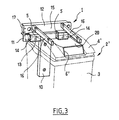
- the container 2 ' has a cover 4' provided 6 'access.
- the latter is substantially rectangular and is formed by a raised wall. 20 of the cover 4 '.
- the device 1 is identical to that of the embodiment illustrated in Figures 1 and 2.
- the device 1 can also be used with a basket forming an element of urban furniture and comprising, like a rolling bin, a tank and a cover.
Landscapes
- Engineering & Computer Science (AREA)
- Mechanical Engineering (AREA)
- Refuse Receptacles (AREA)
- Closures For Containers (AREA)
- Processing Of Solid Wastes (AREA)
- Refuse Collection And Transfer (AREA)
- Accommodation For Nursing Or Treatment Tables (AREA)
Abstract
Description
- la figure 1 représente, schématiquement et partiellement, en perspective, un dispositif conforme à l'invention, permettant de maintenir un conteneur de collecte de déchets à poste fixe, le dispositif étant en position de fermeture,
- la figure 2 représente, schématiquement et partiellement, le dispositif de la figure 1, en position d'ouverture, et
- la figure 3 illustre, schématiquement et partiellement, une variante de mise en oeuvre de l'invention.
Claims (9)
- Dispositif (1) pour maintenir un conteneur de collecte de déchets (2) à poste fixe, le conteneur comportant une cuve (3) et un couvercle pivotant (4) pourvu d'au moins un accès (6) débouchant dans l'espace intérieur de la cuve lorsque le couvercle est en position de fermeture, le dispositif comportant des moyens de fixation verrouillables (11 ; 12) aptes à venir en prise avec la cuve (3), le dispositif (1) comportant en outre au moins un élément de maintien (16) apte à être positionné au-dessus du couvercle lorsque celui-ci est en position de fermeture et à empêcher l'ouverture du couvercle, tout en laissant dégagé ledit accès (6), caractérisé par le fait que les moyens de fixation comprennent une partie de base fixe (11) et une partie mobile (12) articulée sur la partie de base, la partie mobile étant apte à prendre une position d'ouverture libérant la cuve et une position de fermeture dans laquelle la cuve est solidaire du dispositif.
- Dispositif selon la revendication 1, caractérisé par le fait que ledit au moins un élément de maintien (16) comporte au moins un bras sensiblement rectiligne.
- Dispositif selon la revendication 2, caractérisé par le fait qu'il comporte deux bras (16) parallèles aptes à être positionnés de part et d'autre dudit accès (6) du couvercle.
- Dispositif selon la revendication 3, caractérisé par le fait que les deux bras ne sont pas reliés entre eux.
- Dispositif selon l'une quelconque des revendications précédentes, caractérisé par le fait que ledit au moins un bras de maintien (16) est fixé sur la partie mobile (12).
- Dispositif selon l'une quelconque des revendications précédentes, la cuve comportant à l'arrière au moins une poignée (5), caractérisé par le fait que lesdites parties fixe (11) et mobile (12) comportent des éléments de blocage coopérants (13 ; 14) pour retenir la poignée (5) sur le dispositif.
- Dispositif selon l'une quelconque des revendications précédentes, la partie fixe (11) s'étendant suivant un axe longitudinal (X), caractérisé par le fait que les parties fixe (11) et mobile (12) sont articulées entre elles suivant un axe (Y) perpendiculaire à l'axe (X).
- Dispositif selon l'une quelconque des revendications précédentes, caractérisé par le fait qu'il est agencé pour maintenir à poste fixe un unique conteneur.
- Dispositif selon l'une quelconque des revendications précédentes, caractérisé par le fait qu'il comporte un unique moyen de verrouillage (17) pour verrouiller les parties fixe (11) et mobile (12).
Applications Claiming Priority (2)
| Application Number | Priority Date | Filing Date | Title |
|---|---|---|---|
| FR0305156 | 2003-04-28 | ||
| FR0305156A FR2854146B1 (fr) | 2003-04-28 | 2003-04-28 | Dispositif pour maintenir un conteneur de collecte de dechets a poste fixe |
Publications (2)
| Publication Number | Publication Date |
|---|---|
| EP1473251A1 true EP1473251A1 (fr) | 2004-11-03 |
| EP1473251B1 EP1473251B1 (fr) | 2011-06-08 |
Family
ID=32982310
Family Applications (1)
| Application Number | Title | Priority Date | Filing Date |
|---|---|---|---|
| EP04291084A Expired - Lifetime EP1473251B1 (fr) | 2003-04-28 | 2004-04-27 | Dispositif pour maintenir un conteneur de collecte de déchets à poste fixe |
Country Status (3)
| Country | Link |
|---|---|
| EP (1) | EP1473251B1 (fr) |
| AT (1) | ATE512101T1 (fr) |
| FR (1) | FR2854146B1 (fr) |
Cited By (4)
| Publication number | Priority date | Publication date | Assignee | Title |
|---|---|---|---|---|
| GB2471312A (en) * | 2009-06-25 | 2010-12-29 | Recycle 2 Gether Ltd | Bin retaining device |
| FR2959220A1 (fr) * | 2010-04-22 | 2011-10-28 | Michel Alain Billon | Dispositif destine a empecher le basculement des poubelles contenant des dechets menagers. |
| CN106115128A (zh) * | 2016-08-18 | 2016-11-16 | 无锡飞达纺织印染机械有限公司 | 一种家用垃圾桶的固定支架 |
| IT201900020326A1 (it) * | 2019-11-04 | 2021-05-04 | O M G Di Geminiani Gino | Gruppo contenitore per rifiuti. |
Citations (6)
| Publication number | Priority date | Publication date | Assignee | Title |
|---|---|---|---|---|
| US3547273A (en) * | 1968-09-26 | 1970-12-15 | Reuben N Bompart | Garbage can stand with lid holders |
| DE9413464U1 (de) | 1994-05-18 | 1994-10-27 | Paul Villiger Umwelttechnik AG, Oberrüti | Abschließvorrichtung für Mülltonnen |
| GB2298228A (en) * | 1995-02-22 | 1996-08-28 | Edwin Anthony Kurz | Latching device for anchoring a wheeled refuse bin to a wall |
| DE29602468U1 (de) * | 1996-02-13 | 1996-09-12 | Lutz von Wildenradt GmbH, 24613 Aukrug | Vorrichtung zum Verschließen von vorhandenen Abfallbehältern |
| GB2337788A (en) * | 1998-02-17 | 1999-12-01 | John Herd | Wheelie bin lock with bracket mounted retaining member and lock plate insertable within apertures of the bracket to the secure the member |
| GB2346317A (en) * | 1999-02-05 | 2000-08-09 | Paul Verne Tallents | Retaining a refuse container |
-
2003
- 2003-04-28 FR FR0305156A patent/FR2854146B1/fr not_active Expired - Fee Related
-
2004
- 2004-04-27 AT AT04291084T patent/ATE512101T1/de not_active IP Right Cessation
- 2004-04-27 EP EP04291084A patent/EP1473251B1/fr not_active Expired - Lifetime
Patent Citations (6)
| Publication number | Priority date | Publication date | Assignee | Title |
|---|---|---|---|---|
| US3547273A (en) * | 1968-09-26 | 1970-12-15 | Reuben N Bompart | Garbage can stand with lid holders |
| DE9413464U1 (de) | 1994-05-18 | 1994-10-27 | Paul Villiger Umwelttechnik AG, Oberrüti | Abschließvorrichtung für Mülltonnen |
| GB2298228A (en) * | 1995-02-22 | 1996-08-28 | Edwin Anthony Kurz | Latching device for anchoring a wheeled refuse bin to a wall |
| DE29602468U1 (de) * | 1996-02-13 | 1996-09-12 | Lutz von Wildenradt GmbH, 24613 Aukrug | Vorrichtung zum Verschließen von vorhandenen Abfallbehältern |
| GB2337788A (en) * | 1998-02-17 | 1999-12-01 | John Herd | Wheelie bin lock with bracket mounted retaining member and lock plate insertable within apertures of the bracket to the secure the member |
| GB2346317A (en) * | 1999-02-05 | 2000-08-09 | Paul Verne Tallents | Retaining a refuse container |
Cited By (5)
| Publication number | Priority date | Publication date | Assignee | Title |
|---|---|---|---|---|
| GB2471312A (en) * | 2009-06-25 | 2010-12-29 | Recycle 2 Gether Ltd | Bin retaining device |
| FR2959220A1 (fr) * | 2010-04-22 | 2011-10-28 | Michel Alain Billon | Dispositif destine a empecher le basculement des poubelles contenant des dechets menagers. |
| CN106115128A (zh) * | 2016-08-18 | 2016-11-16 | 无锡飞达纺织印染机械有限公司 | 一种家用垃圾桶的固定支架 |
| CN106115128B (zh) * | 2016-08-18 | 2018-10-30 | 无锡飞达纺织印染机械有限公司 | 一种家用垃圾桶的固定支架 |
| IT201900020326A1 (it) * | 2019-11-04 | 2021-05-04 | O M G Di Geminiani Gino | Gruppo contenitore per rifiuti. |
Also Published As
| Publication number | Publication date |
|---|---|
| ATE512101T1 (de) | 2011-06-15 |
| FR2854146A1 (fr) | 2004-10-29 |
| FR2854146B1 (fr) | 2006-06-23 |
| EP1473251B1 (fr) | 2011-06-08 |
Similar Documents
| Publication | Publication Date | Title |
|---|---|---|
| EP1081063B1 (fr) | Dispositif automatique par gravite de verrouillage / deverrouillage du couvercle d'un bac et bac equipe d'un tel dispositif | |
| FR2666076A1 (fr) | Conteneur comprenant un verrou de couvercle. | |
| EP4129764B1 (fr) | Véhicule équipé de barres de toit modulables et inviolables | |
| EP3181491B1 (fr) | Bac pour la collecte de déchets | |
| EP1473251B1 (fr) | Dispositif pour maintenir un conteneur de collecte de déchets à poste fixe | |
| EP1045789B1 (fr) | Dispositif pour le stockage et le transport d'une motocyclette | |
| EP0634344B1 (fr) | Conteneur compartimenté pour la collecte de déchets, notamment d'ordures ménagères | |
| FR2587188A1 (fr) | Corbeille a papier et bride adaptee a la fixation de la corbeille | |
| WO2020193645A1 (fr) | Rack de stockage a acces facilite | |
| FR2707962A1 (fr) | Dispositif de blocage pour conteneur mobile de collecte d'ordures ménagères. | |
| EP0724052B1 (fr) | Poignée de porte de véhicule automobile à montage rapide par système coin-came | |
| EP0477095A1 (fr) | Dispositif de rangement pour roue de secours | |
| FR2728136A1 (fr) | Bac de ramassage a coque de vidange pour tondeuse autoportee a support de bacs amovibles, et tondeuse comportant un tel bac | |
| EP0554185B1 (fr) | Ensemble de rangement comportant une mallette et un support | |
| EP1470984B1 (fr) | Dispositif destiné à faciliter la manipulation d'un bac à deux roues de collecte de déchets | |
| FR2565946A1 (fr) | Poubelle | |
| EP1657229B1 (fr) | Dispositif de compostage de déchets végétaux | |
| FR2846212A1 (fr) | Systeme de separation d'objets disposes sur un support susceptible d'etre en mouvement, du type tapis roulant | |
| EP0592270B1 (fr) | Cuve, porte-cuve et réceptacle à déchets, tel que corbeille à papiers, constitué par de telles pièces | |
| EP1375082A1 (fr) | Ensemble de stockage pour un ouvrage accessible au public | |
| FR2891753A3 (fr) | Recipient de centrifugeuse comprenant une fixation pour poche de sang | |
| EP0916287A2 (fr) | Siège à éléments de garnissage | |
| FR2851550A1 (fr) | Dispositif de fixation d'un couvercle en matiere plastique sur une boite en matiere plastique pour le conditionnement d'articles disposes en vrac dans la boite | |
| FR3003826A1 (fr) | Mecanisme d'inclinaison pour portes-bicyclettes | |
| FR2719031A1 (fr) | Conteneur additionnel à déchets pour conteneur principal et ensemble comprenant deux tels conteneurs séparables l'un de l'autre. |
Legal Events
| Date | Code | Title | Description |
|---|---|---|---|
| PUAI | Public reference made under article 153(3) epc to a published international application that has entered the european phase |
Free format text: ORIGINAL CODE: 0009012 |
|
| AK | Designated contracting states |
Kind code of ref document: A1 Designated state(s): AT BE BG CH CY CZ DE DK EE ES FI FR GB GR HU IE IT LI LU MC NL PL PT RO SE SI SK TR |
|
| AX | Request for extension of the european patent |
Extension state: AL HR LT LV MK |
|
| 17P | Request for examination filed |
Effective date: 20050209 |
|
| AKX | Designation fees paid |
Designated state(s): AT BE BG CH CY CZ DE DK EE ES FI FR GB GR HU IE IT LI LU MC NL PL PT RO SE SI SK TR |
|
| 17Q | First examination report despatched |
Effective date: 20090804 |
|
| GRAP | Despatch of communication of intention to grant a patent |
Free format text: ORIGINAL CODE: EPIDOSNIGR1 |
|
| RIN1 | Information on inventor provided before grant (corrected) |
Inventor name: KNOEFF, ARNOUD ABRAHAM Inventor name: VAN VEEN, PIETER |
|
| GRAS | Grant fee paid |
Free format text: ORIGINAL CODE: EPIDOSNIGR3 |
|
| GRAA | (expected) grant |
Free format text: ORIGINAL CODE: 0009210 |
|
| AK | Designated contracting states |
Kind code of ref document: B1 Designated state(s): AT BE BG CH CY CZ DE DK EE ES FI FR GB GR HU IE IT LI LU MC NL PL PT RO SE SI SK TR |
|
| REG | Reference to a national code |
Ref country code: GB Ref legal event code: FG4D Free format text: NOT ENGLISH |
|
| REG | Reference to a national code |
Ref country code: CH Ref legal event code: EP |
|
| REG | Reference to a national code |
Ref country code: IE Ref legal event code: FG4D Free format text: LANGUAGE OF EP DOCUMENT: FRENCH |
|
| REG | Reference to a national code |
Ref country code: DE Ref legal event code: R096 Ref document number: 602004032939 Country of ref document: DE Effective date: 20110721 |
|
| REG | Reference to a national code |
Ref country code: NL Ref legal event code: T3 |
|
| PG25 | Lapsed in a contracting state [announced via postgrant information from national office to epo] |
Ref country code: SE Free format text: LAPSE BECAUSE OF FAILURE TO SUBMIT A TRANSLATION OF THE DESCRIPTION OR TO PAY THE FEE WITHIN THE PRESCRIBED TIME-LIMIT Effective date: 20110608 |
|
| PG25 | Lapsed in a contracting state [announced via postgrant information from national office to epo] |
Ref country code: ES Free format text: LAPSE BECAUSE OF FAILURE TO SUBMIT A TRANSLATION OF THE DESCRIPTION OR TO PAY THE FEE WITHIN THE PRESCRIBED TIME-LIMIT Effective date: 20110919 Ref country code: GR Free format text: LAPSE BECAUSE OF FAILURE TO SUBMIT A TRANSLATION OF THE DESCRIPTION OR TO PAY THE FEE WITHIN THE PRESCRIBED TIME-LIMIT Effective date: 20110909 Ref country code: AT Free format text: LAPSE BECAUSE OF FAILURE TO SUBMIT A TRANSLATION OF THE DESCRIPTION OR TO PAY THE FEE WITHIN THE PRESCRIBED TIME-LIMIT Effective date: 20110608 Ref country code: SI Free format text: LAPSE BECAUSE OF FAILURE TO SUBMIT A TRANSLATION OF THE DESCRIPTION OR TO PAY THE FEE WITHIN THE PRESCRIBED TIME-LIMIT Effective date: 20110608 Ref country code: CY Free format text: LAPSE BECAUSE OF FAILURE TO SUBMIT A TRANSLATION OF THE DESCRIPTION OR TO PAY THE FEE WITHIN THE PRESCRIBED TIME-LIMIT Effective date: 20110608 Ref country code: FI Free format text: LAPSE BECAUSE OF FAILURE TO SUBMIT A TRANSLATION OF THE DESCRIPTION OR TO PAY THE FEE WITHIN THE PRESCRIBED TIME-LIMIT Effective date: 20110608 |
|
| REG | Reference to a national code |
Ref country code: IE Ref legal event code: FD4D |
|
| PG25 | Lapsed in a contracting state [announced via postgrant information from national office to epo] |
Ref country code: IE Free format text: LAPSE BECAUSE OF FAILURE TO SUBMIT A TRANSLATION OF THE DESCRIPTION OR TO PAY THE FEE WITHIN THE PRESCRIBED TIME-LIMIT Effective date: 20110608 Ref country code: PT Free format text: LAPSE BECAUSE OF FAILURE TO SUBMIT A TRANSLATION OF THE DESCRIPTION OR TO PAY THE FEE WITHIN THE PRESCRIBED TIME-LIMIT Effective date: 20111010 Ref country code: EE Free format text: LAPSE BECAUSE OF FAILURE TO SUBMIT A TRANSLATION OF THE DESCRIPTION OR TO PAY THE FEE WITHIN THE PRESCRIBED TIME-LIMIT Effective date: 20110608 Ref country code: CZ Free format text: LAPSE BECAUSE OF FAILURE TO SUBMIT A TRANSLATION OF THE DESCRIPTION OR TO PAY THE FEE WITHIN THE PRESCRIBED TIME-LIMIT Effective date: 20110608 |
|
| PG25 | Lapsed in a contracting state [announced via postgrant information from national office to epo] |
Ref country code: RO Free format text: LAPSE BECAUSE OF FAILURE TO SUBMIT A TRANSLATION OF THE DESCRIPTION OR TO PAY THE FEE WITHIN THE PRESCRIBED TIME-LIMIT Effective date: 20110608 Ref country code: PL Free format text: LAPSE BECAUSE OF FAILURE TO SUBMIT A TRANSLATION OF THE DESCRIPTION OR TO PAY THE FEE WITHIN THE PRESCRIBED TIME-LIMIT Effective date: 20110608 Ref country code: SK Free format text: LAPSE BECAUSE OF FAILURE TO SUBMIT A TRANSLATION OF THE DESCRIPTION OR TO PAY THE FEE WITHIN THE PRESCRIBED TIME-LIMIT Effective date: 20110608 |
|
| PLBE | No opposition filed within time limit |
Free format text: ORIGINAL CODE: 0009261 |
|
| STAA | Information on the status of an ep patent application or granted ep patent |
Free format text: STATUS: NO OPPOSITION FILED WITHIN TIME LIMIT |
|
| 26N | No opposition filed |
Effective date: 20120309 |
|
| PG25 | Lapsed in a contracting state [announced via postgrant information from national office to epo] |
Ref country code: IT Free format text: LAPSE BECAUSE OF FAILURE TO SUBMIT A TRANSLATION OF THE DESCRIPTION OR TO PAY THE FEE WITHIN THE PRESCRIBED TIME-LIMIT Effective date: 20110608 |
|
| PG25 | Lapsed in a contracting state [announced via postgrant information from national office to epo] |
Ref country code: DK Free format text: LAPSE BECAUSE OF FAILURE TO SUBMIT A TRANSLATION OF THE DESCRIPTION OR TO PAY THE FEE WITHIN THE PRESCRIBED TIME-LIMIT Effective date: 20110608 |
|
| REG | Reference to a national code |
Ref country code: DE Ref legal event code: R097 Ref document number: 602004032939 Country of ref document: DE Effective date: 20120309 |
|
| PG25 | Lapsed in a contracting state [announced via postgrant information from national office to epo] |
Ref country code: MC Free format text: LAPSE BECAUSE OF NON-PAYMENT OF DUE FEES Effective date: 20120430 |
|
| REG | Reference to a national code |
Ref country code: CH Ref legal event code: PL |
|
| GBPC | Gb: european patent ceased through non-payment of renewal fee |
Effective date: 20120427 |
|
| PG25 | Lapsed in a contracting state [announced via postgrant information from national office to epo] |
Ref country code: GB Free format text: LAPSE BECAUSE OF NON-PAYMENT OF DUE FEES Effective date: 20120427 Ref country code: CH Free format text: LAPSE BECAUSE OF NON-PAYMENT OF DUE FEES Effective date: 20120430 Ref country code: LI Free format text: LAPSE BECAUSE OF NON-PAYMENT OF DUE FEES Effective date: 20120430 |
|
| PG25 | Lapsed in a contracting state [announced via postgrant information from national office to epo] |
Ref country code: BG Free format text: LAPSE BECAUSE OF FAILURE TO SUBMIT A TRANSLATION OF THE DESCRIPTION OR TO PAY THE FEE WITHIN THE PRESCRIBED TIME-LIMIT Effective date: 20110908 |
|
| PG25 | Lapsed in a contracting state [announced via postgrant information from national office to epo] |
Ref country code: TR Free format text: LAPSE BECAUSE OF FAILURE TO SUBMIT A TRANSLATION OF THE DESCRIPTION OR TO PAY THE FEE WITHIN THE PRESCRIBED TIME-LIMIT Effective date: 20110608 |
|
| PG25 | Lapsed in a contracting state [announced via postgrant information from national office to epo] |
Ref country code: LU Free format text: LAPSE BECAUSE OF NON-PAYMENT OF DUE FEES Effective date: 20120427 |
|
| PG25 | Lapsed in a contracting state [announced via postgrant information from national office to epo] |
Ref country code: HU Free format text: LAPSE BECAUSE OF FAILURE TO SUBMIT A TRANSLATION OF THE DESCRIPTION OR TO PAY THE FEE WITHIN THE PRESCRIBED TIME-LIMIT Effective date: 20040427 |
|
| REG | Reference to a national code |
Ref country code: FR Ref legal event code: PLFP Year of fee payment: 13 |
|
| REG | Reference to a national code |
Ref country code: FR Ref legal event code: PLFP Year of fee payment: 14 |
|
| REG | Reference to a national code |
Ref country code: FR Ref legal event code: PLFP Year of fee payment: 15 |
|
| REG | Reference to a national code |
Ref country code: DE Ref legal event code: R082 Ref document number: 602004032939 Country of ref document: DE Representative=s name: MAIWALD PATENTANWALTS- UND RECHTSANWALTSGESELL, DE |
|
| PGFP | Annual fee paid to national office [announced via postgrant information from national office to epo] |
Ref country code: NL Payment date: 20180418 Year of fee payment: 15 |
|
| PGFP | Annual fee paid to national office [announced via postgrant information from national office to epo] |
Ref country code: DE Payment date: 20180420 Year of fee payment: 15 |
|
| PGFP | Annual fee paid to national office [announced via postgrant information from national office to epo] |
Ref country code: FR Payment date: 20180424 Year of fee payment: 15 Ref country code: BE Payment date: 20180418 Year of fee payment: 15 |
|
| REG | Reference to a national code |
Ref country code: DE Ref legal event code: R082 Ref document number: 602004032939 Country of ref document: DE Representative=s name: MAIWALD PATENTANWALTS- UND RECHTSANWALTSGESELL, DE Ref country code: DE Ref legal event code: R081 Ref document number: 602004032939 Country of ref document: DE Owner name: PLASTIC OMNIUM SYSTEMES URBAINS, FR Free format text: FORMER OWNER: COMPAGNIE PLASTIC OMNIUM, LYON, FR |
|
| REG | Reference to a national code |
Ref country code: BE Ref legal event code: PD Owner name: PLASTIC OMNIUM SYSTEMES URBAINS; FR Free format text: DETAILS ASSIGNMENT: CHANGE OF OWNER(S), CESSION; FORMER OWNER NAME: COMPAGNIE PLASTIC OMNIUM Effective date: 20190102 |
|
| REG | Reference to a national code |
Ref country code: NL Ref legal event code: PD Owner name: PLASTIC OMNIUM SYSTEMES URBAINS; FR Free format text: DETAILS ASSIGNMENT: CHANGE OF OWNER(S), ASSIGNMENT; FORMER OWNER NAME: COMPAGNIE PLASTIC OMNIUM Effective date: 20181228 |
|
| REG | Reference to a national code |
Ref country code: DE Ref legal event code: R119 Ref document number: 602004032939 Country of ref document: DE |
|
| REG | Reference to a national code |
Ref country code: NL Ref legal event code: MM Effective date: 20190501 |
|
| REG | Reference to a national code |
Ref country code: BE Ref legal event code: MM Effective date: 20190430 |
|
| PG25 | Lapsed in a contracting state [announced via postgrant information from national office to epo] |
Ref country code: DE Free format text: LAPSE BECAUSE OF NON-PAYMENT OF DUE FEES Effective date: 20191101 Ref country code: NL Free format text: LAPSE BECAUSE OF NON-PAYMENT OF DUE FEES Effective date: 20190501 |
|
| PG25 | Lapsed in a contracting state [announced via postgrant information from national office to epo] |
Ref country code: BE Free format text: LAPSE BECAUSE OF NON-PAYMENT OF DUE FEES Effective date: 20190430 |
|
| PG25 | Lapsed in a contracting state [announced via postgrant information from national office to epo] |
Ref country code: FR Free format text: LAPSE BECAUSE OF NON-PAYMENT OF DUE FEES Effective date: 20190430 |