EP1473458B1 - Startsystem für gasmotor mit vorzündung - Google Patents
Startsystem für gasmotor mit vorzündung Download PDFInfo
- Publication number
- EP1473458B1 EP1473458B1 EP02712287.8A EP02712287A EP1473458B1 EP 1473458 B1 EP1473458 B1 EP 1473458B1 EP 02712287 A EP02712287 A EP 02712287A EP 1473458 B1 EP1473458 B1 EP 1473458B1
- Authority
- EP
- European Patent Office
- Prior art keywords
- fuel
- fuel injection
- engine
- pilot oil
- engine speed
- Prior art date
- Legal status (The legal status is an assumption and is not a legal conclusion. Google has not performed a legal analysis and makes no representation as to the accuracy of the status listed.)
- Expired - Lifetime
Links
- 239000000446 fuel Substances 0.000 claims description 181
- 238000002347 injection Methods 0.000 claims description 116
- 239000007924 injection Substances 0.000 claims description 116
- 239000007788 liquid Substances 0.000 claims description 51
- 238000002485 combustion reaction Methods 0.000 claims description 32
- 239000007858 starting material Substances 0.000 claims description 29
- 239000000203 mixture Substances 0.000 claims description 19
- 230000003247 decreasing effect Effects 0.000 claims description 2
- 239000003921 oil Substances 0.000 description 88
- 239000007789 gas Substances 0.000 description 64
- 230000006835 compression Effects 0.000 description 9
- 238000007906 compression Methods 0.000 description 9
- 239000002737 fuel gas Substances 0.000 description 8
- 230000036461 convulsion Effects 0.000 description 5
- 230000005611 electricity Effects 0.000 description 5
- 238000012360 testing method Methods 0.000 description 5
- 239000000295 fuel oil Substances 0.000 description 3
- 229930195733 hydrocarbon Natural products 0.000 description 3
- 150000002430 hydrocarbons Chemical class 0.000 description 3
- 239000000498 cooling water Substances 0.000 description 2
- 238000001514 detection method Methods 0.000 description 2
- 238000004880 explosion Methods 0.000 description 2
- 238000009434 installation Methods 0.000 description 2
- 230000007246 mechanism Effects 0.000 description 2
- 238000010248 power generation Methods 0.000 description 2
- 230000009467 reduction Effects 0.000 description 2
- 230000009471 action Effects 0.000 description 1
- 230000008878 coupling Effects 0.000 description 1
- 238000010168 coupling process Methods 0.000 description 1
- 238000005859 coupling reaction Methods 0.000 description 1
- 230000007423 decrease Effects 0.000 description 1
- 230000007547 defect Effects 0.000 description 1
- 238000010586 diagram Methods 0.000 description 1
- 238000006073 displacement reaction Methods 0.000 description 1
- 238000000034 method Methods 0.000 description 1
- 230000002093 peripheral effect Effects 0.000 description 1
- 230000008569 process Effects 0.000 description 1
- 230000004044 response Effects 0.000 description 1
- 230000007704 transition Effects 0.000 description 1
Images



Classifications
-
- F—MECHANICAL ENGINEERING; LIGHTING; HEATING; WEAPONS; BLASTING
- F02—COMBUSTION ENGINES; HOT-GAS OR COMBUSTION-PRODUCT ENGINE PLANTS
- F02N—STARTING OF COMBUSTION ENGINES; STARTING AIDS FOR SUCH ENGINES, NOT OTHERWISE PROVIDED FOR
- F02N99/00—Subject matter not provided for in the other groups of this subclass
- F02N99/002—Starting combustion engines by ignition means
- F02N99/006—Providing a combustible mixture inside the cylinder
-
- F—MECHANICAL ENGINEERING; LIGHTING; HEATING; WEAPONS; BLASTING
- F02—COMBUSTION ENGINES; HOT-GAS OR COMBUSTION-PRODUCT ENGINE PLANTS
- F02B—INTERNAL-COMBUSTION PISTON ENGINES; COMBUSTION ENGINES IN GENERAL
- F02B19/00—Engines characterised by precombustion chambers
- F02B19/10—Engines characterised by precombustion chambers with fuel introduced partly into pre-combustion chamber, and partly into cylinder
-
- F—MECHANICAL ENGINEERING; LIGHTING; HEATING; WEAPONS; BLASTING
- F02—COMBUSTION ENGINES; HOT-GAS OR COMBUSTION-PRODUCT ENGINE PLANTS
- F02B—INTERNAL-COMBUSTION PISTON ENGINES; COMBUSTION ENGINES IN GENERAL
- F02B19/00—Engines characterised by precombustion chambers
- F02B19/10—Engines characterised by precombustion chambers with fuel introduced partly into pre-combustion chamber, and partly into cylinder
- F02B19/1019—Engines characterised by precombustion chambers with fuel introduced partly into pre-combustion chamber, and partly into cylinder with only one pre-combustion chamber
- F02B19/108—Engines characterised by precombustion chambers with fuel introduced partly into pre-combustion chamber, and partly into cylinder with only one pre-combustion chamber with fuel injection at least into pre-combustion chamber, i.e. injector mounted directly in the pre-combustion chamber
- F02B19/1085—Engines characterised by precombustion chambers with fuel introduced partly into pre-combustion chamber, and partly into cylinder with only one pre-combustion chamber with fuel injection at least into pre-combustion chamber, i.e. injector mounted directly in the pre-combustion chamber controlling fuel injection
-
- F—MECHANICAL ENGINEERING; LIGHTING; HEATING; WEAPONS; BLASTING
- F02—COMBUSTION ENGINES; HOT-GAS OR COMBUSTION-PRODUCT ENGINE PLANTS
- F02B—INTERNAL-COMBUSTION PISTON ENGINES; COMBUSTION ENGINES IN GENERAL
- F02B19/00—Engines characterised by precombustion chambers
- F02B19/12—Engines characterised by precombustion chambers with positive ignition
-
- F—MECHANICAL ENGINEERING; LIGHTING; HEATING; WEAPONS; BLASTING
- F02—COMBUSTION ENGINES; HOT-GAS OR COMBUSTION-PRODUCT ENGINE PLANTS
- F02D—CONTROLLING COMBUSTION ENGINES
- F02D19/00—Controlling engines characterised by their use of non-liquid fuels, pluralities of fuels, or non-fuel substances added to the combustible mixtures
- F02D19/06—Controlling engines characterised by their use of non-liquid fuels, pluralities of fuels, or non-fuel substances added to the combustible mixtures peculiar to engines working with pluralities of fuels, e.g. alternatively with light and heavy fuel oil, other than engines indifferent to the fuel consumed
- F02D19/0602—Control of components of the fuel supply system
- F02D19/0605—Control of components of the fuel supply system to adjust the fuel pressure or temperature
-
- F—MECHANICAL ENGINEERING; LIGHTING; HEATING; WEAPONS; BLASTING
- F02—COMBUSTION ENGINES; HOT-GAS OR COMBUSTION-PRODUCT ENGINE PLANTS
- F02D—CONTROLLING COMBUSTION ENGINES
- F02D19/00—Controlling engines characterised by their use of non-liquid fuels, pluralities of fuels, or non-fuel substances added to the combustible mixtures
- F02D19/06—Controlling engines characterised by their use of non-liquid fuels, pluralities of fuels, or non-fuel substances added to the combustible mixtures peculiar to engines working with pluralities of fuels, e.g. alternatively with light and heavy fuel oil, other than engines indifferent to the fuel consumed
- F02D19/0602—Control of components of the fuel supply system
- F02D19/0607—Control of components of the fuel supply system to adjust the fuel mass or volume flow
- F02D19/061—Control of components of the fuel supply system to adjust the fuel mass or volume flow by controlling fuel injectors
-
- F—MECHANICAL ENGINEERING; LIGHTING; HEATING; WEAPONS; BLASTING
- F02—COMBUSTION ENGINES; HOT-GAS OR COMBUSTION-PRODUCT ENGINE PLANTS
- F02D—CONTROLLING COMBUSTION ENGINES
- F02D19/00—Controlling engines characterised by their use of non-liquid fuels, pluralities of fuels, or non-fuel substances added to the combustible mixtures
- F02D19/06—Controlling engines characterised by their use of non-liquid fuels, pluralities of fuels, or non-fuel substances added to the combustible mixtures peculiar to engines working with pluralities of fuels, e.g. alternatively with light and heavy fuel oil, other than engines indifferent to the fuel consumed
- F02D19/08—Controlling engines characterised by their use of non-liquid fuels, pluralities of fuels, or non-fuel substances added to the combustible mixtures peculiar to engines working with pluralities of fuels, e.g. alternatively with light and heavy fuel oil, other than engines indifferent to the fuel consumed simultaneously using pluralities of fuels
- F02D19/10—Controlling engines characterised by their use of non-liquid fuels, pluralities of fuels, or non-fuel substances added to the combustible mixtures peculiar to engines working with pluralities of fuels, e.g. alternatively with light and heavy fuel oil, other than engines indifferent to the fuel consumed simultaneously using pluralities of fuels peculiar to compression-ignition engines in which the main fuel is gaseous
-
- F—MECHANICAL ENGINEERING; LIGHTING; HEATING; WEAPONS; BLASTING
- F02—COMBUSTION ENGINES; HOT-GAS OR COMBUSTION-PRODUCT ENGINE PLANTS
- F02D—CONTROLLING COMBUSTION ENGINES
- F02D41/00—Electrical control of supply of combustible mixture or its constituents
- F02D41/30—Controlling fuel injection
- F02D41/38—Controlling fuel injection of the high pressure type
- F02D41/40—Controlling fuel injection of the high pressure type with means for controlling injection timing or duration
- F02D41/402—Multiple injections
- F02D41/403—Multiple injections with pilot injections
-
- F—MECHANICAL ENGINEERING; LIGHTING; HEATING; WEAPONS; BLASTING
- F02—COMBUSTION ENGINES; HOT-GAS OR COMBUSTION-PRODUCT ENGINE PLANTS
- F02M—SUPPLYING COMBUSTION ENGINES IN GENERAL WITH COMBUSTIBLE MIXTURES OR CONSTITUENTS THEREOF
- F02M21/00—Apparatus for supplying engines with non-liquid fuels, e.g. gaseous fuels stored in liquid form
- F02M21/02—Apparatus for supplying engines with non-liquid fuels, e.g. gaseous fuels stored in liquid form for gaseous fuels
-
- F—MECHANICAL ENGINEERING; LIGHTING; HEATING; WEAPONS; BLASTING
- F02—COMBUSTION ENGINES; HOT-GAS OR COMBUSTION-PRODUCT ENGINE PLANTS
- F02D—CONTROLLING COMBUSTION ENGINES
- F02D41/00—Electrical control of supply of combustible mixture or its constituents
- F02D41/02—Circuit arrangements for generating control signals
- F02D41/04—Introducing corrections for particular operating conditions
- F02D41/06—Introducing corrections for particular operating conditions for engine starting or warming up
- F02D41/062—Introducing corrections for particular operating conditions for engine starting or warming up for starting
-
- Y—GENERAL TAGGING OF NEW TECHNOLOGICAL DEVELOPMENTS; GENERAL TAGGING OF CROSS-SECTIONAL TECHNOLOGIES SPANNING OVER SEVERAL SECTIONS OF THE IPC; TECHNICAL SUBJECTS COVERED BY FORMER USPC CROSS-REFERENCE ART COLLECTIONS [XRACs] AND DIGESTS
- Y02—TECHNOLOGIES OR APPLICATIONS FOR MITIGATION OR ADAPTATION AGAINST CLIMATE CHANGE
- Y02T—CLIMATE CHANGE MITIGATION TECHNOLOGIES RELATED TO TRANSPORTATION
- Y02T10/00—Road transport of goods or passengers
- Y02T10/10—Internal combustion engine [ICE] based vehicles
- Y02T10/12—Improving ICE efficiencies
-
- Y—GENERAL TAGGING OF NEW TECHNOLOGICAL DEVELOPMENTS; GENERAL TAGGING OF CROSS-SECTIONAL TECHNOLOGIES SPANNING OVER SEVERAL SECTIONS OF THE IPC; TECHNICAL SUBJECTS COVERED BY FORMER USPC CROSS-REFERENCE ART COLLECTIONS [XRACs] AND DIGESTS
- Y02—TECHNOLOGIES OR APPLICATIONS FOR MITIGATION OR ADAPTATION AGAINST CLIMATE CHANGE
- Y02T—CLIMATE CHANGE MITIGATION TECHNOLOGIES RELATED TO TRANSPORTATION
- Y02T10/00—Road transport of goods or passengers
- Y02T10/10—Internal combustion engine [ICE] based vehicles
- Y02T10/30—Use of alternative fuels, e.g. biofuels
-
- Y—GENERAL TAGGING OF NEW TECHNOLOGICAL DEVELOPMENTS; GENERAL TAGGING OF CROSS-SECTIONAL TECHNOLOGIES SPANNING OVER SEVERAL SECTIONS OF THE IPC; TECHNICAL SUBJECTS COVERED BY FORMER USPC CROSS-REFERENCE ART COLLECTIONS [XRACs] AND DIGESTS
- Y02—TECHNOLOGIES OR APPLICATIONS FOR MITIGATION OR ADAPTATION AGAINST CLIMATE CHANGE
- Y02T—CLIMATE CHANGE MITIGATION TECHNOLOGIES RELATED TO TRANSPORTATION
- Y02T10/00—Road transport of goods or passengers
- Y02T10/10—Internal combustion engine [ICE] based vehicles
- Y02T10/40—Engine management systems
Definitions
- the present invention relates to a starter for a precombustion chamber type pilot oil ignition gas engine in which a precombustion chamber with liquid fuel injection valve is provided in a cylinder head, and a mixture of air and gaseous fuel that is introduced into a main combustion chamber and compressed is ignited and burnt by pilot oil injected from the liquid fuel injection valve.
- the engine shown in FIG. 8 is known as a precombustion chamber type pilot oil ignition gas engine that drives a stationary type of power generation installation for industrial or public use.
- This type of gas engine 1 has a cylinder liner (cylinder) 2, a piston 3 that moves reciprocally up and down inside the cylinder liner 2, and a precombustion chamber unit 6 with liquid fuel injection valve that is provided with a liquid fuel injection valve 4 and a precombustion chamber 5.
- Fuel gas gaseous fuel
- a main combustion chamber 8 which walls are formed by the cylinder liner 2, the piston 3, and the cylinder head 7.
- fuel oil corresponding to approximately 1% of the total quantity of heat is injected as pilot oil from the liquid fuel injection valve 4 into the precombustion chamber 5. This results in the pilot oil being compression ignited in a high temperature - high pressure atmosphere and the fuel gas inside the main combustion chamber 8 is then burnt using the pilot oil as an ignition source.
- a jerk fuel injection pump which is designed so that a small discharge quantity can be reliably obtained, is used as the fuel injection pump for supplying fuel oil (i.e., pilot oil) to the liquid fuel injection valve 4. Because this jerk fuel injection pump is driven by revolution of the engine via a camshaft, it is affected by an engine speed.
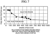
- this jerk fuel pump the relationship between the position of the fuel rack (fuel control rod) which starts fuel injection and the number of engine revolutions (i.e., the engine speed) is shown in FIG. 7 . As can be seen in FIG.
- the smaller the indicated value for the fuel rack position that sets the fuel injection quantity the wider the range of the engine speed where there is no injection (i.e., the region of the engine revolutions where injection of the fuel oil from the liquid fuel injection valve 4 is not started). For example, if the fuel rack position is set to 8 mm, which is the position corresponding to the discharge quantity of the pilot oil is approximately 1% of the total quantity of heat, the pilot oil is not injected from the liquid fuel injection valve until the engine speed reaches approximately 600 rpm.
- this gas engine 1 the compression ratio is lowered in comparison with a diesel engine in order to avoid knocking during gas operation. Therefore, particularly when the engine is in transition from starting to run-up, if the injection of pilot oil from the liquid fuel injection valve has started, compression ignition of this pilot oil is only achieved with difficulty. In particular, if the engine cooling water is at a low temperature, the compression ignition becomes noticeably more difficult.
- an ignition device 9 such as an ignition plug or a glow plug, is provided in addition to the liquid fuel injection valve 4 so that fuel gas introduced into the main combustion chamber 8 is ignited and the engine is started.
- the ignition device 9 is required in addition to the liquid fuel injection valve 4
- Another example of such a gas engine is shown in US-5450829 .
- the present invention was conceived in view of the above circumstances and it is an object thereof to provide a starter for pilot oil ignition gas engine that can reliably inject pilot oil from a liquid fuel injection valve from the time the engine is started, and that can smoothly start the engine.
- the present invention has the following features.
- the first aspect of the present invention is a starter for pilot oil ignition according to claim 1.
- gaseous fuel from a gaseous fuel supply source is mixed with air from an intake port of the cylinder head to form a fuel-air mixture, which is then supplied to the main combustion chamber and compressed by the piston.
- a portion of this compressed fuel-air mixture enters the precombustion chamber and, in the latter half of the compression stroke of the piston, is ignited by pilot oil injected from the liquid fuel injection valve by the operation of the fuel injection pumps.
- the portion of the fuel-air mixture remaining inside the main combustion chamber is then burned by the flames created by this ignition.
- the controller operates and the position of the fuel control rod that adjusts the discharge quantity of the fuel injection pumps is controlled based on the engine speed.
- the discharge quantity of the fuel injection pumps that cause pilot oil to be injected from the liquid fuel injection valve is secured.
- this starter for pilot oil ignition gas engine by adjusting the movement of the fuel control rod to a position where the discharge quantity of the fuel injection pump in the low speed region of the engine speed is increased, it is possible to inject pilot oil from the liquid fuel injection valve from the time of starting of the engine. As a result, the ignition and combustion of a fuel-air mixture of gaseous fuel and air inside the main combustion chamber is performed with certainty and it is possible to start the engine smoothly.
- the second aspect of the present invention is the starter for pilot oil ignition gas engine described above, wherein, in a low speed region of the engine speed, the controller controls the fuel control rod in a position where the discharge quantity of the fuel injection pump is increased, while, in a high speed region of the engine speed, the controller controls the fuel control rod in a position where the discharge quantity of the fuel injection pump is decreased.
- the third aspect of the present invention is the starter for pilot oil ignition gas engine according to the above described second aspect, wherein, in the low speed region where the engine speed is a predetermined value or less, the position of fuel control rod is a fixed position where the discharge quantity of the fuel injection pump is at maximum, while, in the high speed region where the engine speed is a predetermined value or greater, the position of fuel control rod is a fixed position where the discharge quantity of the fuel injection pump is at minimum, while, in an intermediate speed region between the low speed region and the high speed region, the discharge quantity of the fuel injection pump changes in accordance with the engine speed from a fixed position where the discharge quantity of the fuel injection pump is at maximum to a fixed position where the discharge quantity of the fuel injection pump is at minimum.
- the fourth aspect of the present invention is the starter for pilot oil ignition gas engine according to the above described first through third aspects, wherein the controller is provided with an engine speed sensor that detects the engine speed, a position control actuator that adjusts a position of the fuel control rod by moving the fuel control rod, and a control apparatus that, based on a relationship between the engine speed and a position of the fuel control rod that is set in advance, calculates a control objective position for the fuel control rod relative to the engine speed detected by the engine speed sensor, and moves the position control actuator such that the position of the fuel control rod is adjusted to the calculated control objective position.
- the controller is provided with an engine speed sensor that detects the engine speed, a position control actuator that adjusts a position of the fuel control rod by moving the fuel control rod, and a control apparatus that, based on a relationship between the engine speed and a position of the fuel control rod that is set in advance, calculates a control objective position for the fuel control rod relative to the engine speed detected by the engine speed sensor, and moves the position control actuator such that the position
- the position of the fuel control rod is controlled by the control apparatus using the position control actuator, and the discharge quantity of the fuel injection pumps is appropriately set to the quantity of pilot oil needed to start injection by the liquid fuel injection valves in accordance with the engine speed detected by the engine speed sensor.
- the injection of pilot oil from the liquid fuel injection valves into the precombustion chamber proceeds even more efficiently and the engine is started smoothly and reliably.
- the fifth aspect of the present invention is the starter for pilot oil ignition gas engine according to the above described first through fourth aspects, wherein, in the cylinder head there is further provided an ignition device that performs an ignition operation before the pilot oil is injected from the liquid fuel injection valve, and ignites the fuel air mixture of gaseous fuel and air that is compressed inside the main combustion chamber.
- the sixth aspect of the present invention is the starter for pilot oil ignition gas engine according to the above described fifth aspect, wherein the ignition device stops ignition operation when the engine speed reaches the rated speed.
- 10 is a pilot oil ignition gas engine (hereinafter abbreviated to "gas engine”).
- gas engine 10 forms a portion of a stationary power generation installation as a result of a power generator 12 being linked via a coupling 11 to an output shaft thereof.
- the gas engine 10 has a structure in which a cylinder head 7 is mounted on a cylinder liner 2 inside which is inserted a piston 3. Inside the cylinder head 7, the gas engine 10 is further provided with an ignition device 9 and also with a precombustion chamber unit 6 with liquid fuel injection valve that is provided with a liquid fuel injection valve 4 and a precombustion chamber 5.
- the description below of portions peripheral to the combustion chamber, such as the cylinder head 7 of the gas engine 10 is based, according to necessity, on FIG. 8 .
- 13 is a jerk fuel injection pump (i.e., a fuel injection pump) provided for each cylinder head 7 of the gas engine 10.
- the jerk fuel injection pumps 13 are driven by camshafts linked via a gear train, which is formed by an intermediate gear or the like, to a crankshaft of the gas engine 10, and are set such that a small amount of oil is injected in a stable manner. Pilot oil discharged from the fuel injection pumps 13 is supplied via pilot oil pipes (not shown) to the liquid fuel injection valves 4 provided in each cylinder head 7.
- a fuel rack (i.e., a fuel control rod) 14 is linked to each fuel injection pump 13 and simultaneously operates mechanism portions that set the discharge quantity of pilot oil in each fuel injection pump 13.
- the position of the fuel rack 14 can be moved by the operation of a rack control actuator (i.e., a position control actuator) 15 linked to the fuel rack 14.
- the discharge quantity of pilot oil is set relative to the position of the fuel rack 14.
- the rack control actuator 15 is constructed such that it is moved as a result of an operating rod being pulled by an electromagnetic coil, and the distance of the movement of the operating rod is set by the size of quantity of electricity supplied to the electromagnetic coil.
- An example of a relationship between the position of the fuel rack 14 moved by the rack control actuator 15 and the size of the quantity of electricity (i.e., the current) supplied to the rack control actuator 15 is shown in FIG. 2 .
- the speed sensor 16 is a speed sensor that detects the engine speed of the gas engine 10.
- the speed sensor 16 is formed by a magnetic pickup or the like, and is positioned so as to face teeth surfaces of a ring gear 17 mounted on the crankshaft of the gas engine 10.
- the speed sensor 16 detects the teeth surfaces of the ring gear 17 and sends pulses that are thereby generated to a control apparatus 18.
- the control apparatus 18 counts the pulses sent from the speed sensor 16 per unit time, measures the number of engine revolutions (i.e., the engine speed), and calculates a position for the fuel rack 14 that is the control objective for that particular engine speed (i.e., a control objective position) based on a control objective line C2 of the relationship between the engine speed and the position of the fuel rack shown in FIG. 3 .
- control apparatus 18 determines the quantity of electricity corresponding to the control objective position calculated for the fuel rack 14 based on the relationship shown in FIG. 2 , and this is then output to the rack control actuator 15 as a command signal.
- a controller 19 that controls the position of the fuel rack 14, which adjusts the discharge quantity of the fuel injection pumps 13, based on the engine speed is formed by the rack control actuator 15, the speed sensor 16, and the control apparatus 18.
- FIG. 3 shows the relationships obtained when, from the characteristics shown in FIG. 4 , the minimum engine speed in the injection region where the injection of pilot oil from the liquid fuel injection valve 14 is commenced is determined at each position of the fuel rack 14, and this minimum engine speed is then corresponded to the position of the fuel rack 14. From the results shown in FIG. 3 , the characteristic curve C1 showing the boundary between the injection region and the non-injection region is obtained.
- the control objective position of the fuel rack 14 is set at a fixed position of 15 mm, at which position the liquid fuel injection valves 4 inject pilot oil, with a quantity of pilot oil corresponding to a quantity of heat ratio of approximately 8% of the quantity of heat required for rated load operation of the engine taken as the maximum injection quantity.
- the control objective position of the fuel rack 14 is set at a fixed position of 8 mm at which position pilot oil corresponding to 1%, as quantity of heat ratio, is injected.
- the control objective position of the fuel rack 14 is set so as to become gradually smaller from a position of 15 mm to a position of 8 mm.
- the control objective position of the fuel rack is set using the control objective line C2 such that there is a displacement from the characteristic curve C1 that forms the boundary between injection region and the non-injection region of the liquid fuel injection valve 4.
- the control objective position of the fuel rack 14 is set at a uniform fixed position regardless of the engine speed.
- fuel gas i.e., a gaseous fuel
- a gaseous fuel supply source not shown
- the gaseous fuel and air are mixed together in the intake port or the like to form a fuel-air mixture that is then supplied to the main combustion chamber 8.
- This fuel-air mixture is compressed by the piston 3 inside the main combustion chamber 8.
- a portion of the compressed fuel-air mixture goes into the precombustion chamber 5 and, in the latter half of the compression stroke of the piston 3, is ignited by pilot oil injected from the liquid fuel injection valves 4 by the operation of the fuel injection pumps 13.
- the portion of the fuel-air mixture remaining inside the main combustion chamber 8 is then burned by the flames created by the ignition, causing the gas engine 10 to commence revolution.
- the gaseous fuel supplied to the interior of the main combustion chamber 8 is increased by the operation of an engine governor.
- the engine speed of the gas engine 10 gradually increases and reaches a rated speed after a predetermined time.
- the controller 19 operates such that the control apparatus 18 thereof counts the pulses detected by the speed sensor 16 and calculates the engine speed.
- the control apparatus 18 determines a control objective position for the fuel rack that corresponds to the calculated engine speed based on the control objective line C2 shown in FIG. 3 . Because the maximum control objective position corresponding to the low engine speed region is set by the control objective line C2, the control apparatus 18 sends a signal commanding a large quantity of electricity corresponding to this control objective position to the rack control actuator 15.
- the rack control actuator 15 moves the position of the fuel rack 14 by the maximum distance, and the fuel injection pumps 13 are adjusted such that the maximum quantity of pilot oil is discharged.
- the quantity of pilot oil discharged from the fuel injection pumps 13 i.e., the quantity of compressed oil
- the oil pressure inside the pilot oil pipes linking the fuel injection pumps 13 to the liquid fuel injection valves 4 is raised enough for pilot oil to be reliably injected from the liquid fuel injection valves 4 even at a low engine speed.
- the ignition and burning of fuel-air mixture inside the main combustion chamber 8 is reliably performed, and starting of the gas engine 10 is achieved smoothly.
- the maximum discharge quantity from the fuel injection pumps 13 does not exceed the quantity of heat ratio of approximately 8% relative to when the engine is operating at rated load operation, as described above. Accordingly, it is not possible to generate sufficient torque to raise the gas engine 10 to the rated speed, and no obstacle to the operation of the gas engine 10, namely, to the control of the engine speed by the engine governor is created.
- the control apparatus 18 adjusts the control objective position of the fuel rack 14 such that it is gradually lowered from the maximum position, in accordance with the control objective line C2 shown in FIG. 3 , based on the results of detections by the speed sensor 16.
- the rack control actuator 15 adjusts the position of the liquid fuel injection valve to the control objective position such that approximately 1%, as a quantity of heat percentage, of pilot oil is injected from the liquid fuel injection pump 14.
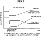
- the ignition plugs (ignition devices) 9 provided in the cylinder head 7 are operated so that the fuel-air mixture inside the main combustion chamber 8 is ignited.
- the precombustion chamber 5 is heated by heat generated by the ignition and combustion of the fuel-air mixture so that the compression ignition of the pilot oil injected from the liquid fuel injection valves 4 is accelerated, the ratio of misfires at engine run-up is reduced and the combustion stability is improved.
- the total hydrocarbons in the exhaust gas are reduced and explosions in the exhaust pipe system are avoided, allowing a reduction in the rise time before the rated speed is reached to be achieved.
- the operating time of the ignition of the ignition plug 9 is set to the commencement time of the starting, and the ignition plug 9 ignites either simultaneously or immediately prior to the injection of pilot oil from the liquid fuel combustion valve 4.
- the stopping time of the ignition is set to the point when the rated speed of the gas engine 10 is detected by the speed sensor 16, or the point when it is detected that the voltage generated by the generator 12 has reached a rated voltage.
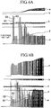
- FIGS. 6A and 6B show the results recorded when a pilot oil ignition gas engine test apparatus having a single cylinder with a cylinder diameter of 260 mm is operated with the fuel rack position set to 8 mm or 15 mm and the ignition plug having been in operation from starting.
- the data for starting of engine is made up of the pressure a inside the pilot oil pipe, the valve lift b of the liquid fuel injection valve, the pressure c inside the gaseous fuel supply pipe, the engine speed d, and the pressure e inside the main combustion chamber.
- a and B correspond to the position of the fuel rack being set to 8 mm and 15 mm respectively.
- the pressure a inside the pilot oil pipe has reached a sufficient pressure to open the liquid fuel injection valve from the first starting cycle S1, and the pilot oil is injected from the liquid fuel injection valve (there is a valve lift b signal). Accordingly, the pressure e inside the main combustion chamber also increases due to the burning of the fuel-air mixture to accompany the supply of fuel gas from the third cycle S3, and the run-up in the engine speed becomes faster.
- the rack control actuator 15 is moved by an electromagnetic coil pulling an operating rod, however, instead of this, it is also possible to employ a structure in which a rotation of an electric servomotor is converted into a rectilinear motion by a bolt mechanism formed by screwing a nut onto a bolt shaft, and for the fuel rack 14 to be moved by this rectilinear motion.
- the rack control actuator 15 may be a hydraulic servo cylinder and is not particularly restricted provided that it is able to move the fuel rack 14 to a predetermined position in response to a command from the control apparatus 18.
- a structure is employed in which the engine speed is measured using pulses generated by the detection of teeth surfaces of a ring gear 17 mounted on a crank shaft using an electromagnetic pickup or the like, however, instead of this it is also possible measure the engine speed by directly measuring the number of revolutions of a camshaft or some other shaft that rotates in conjunction with the engine crankshaft using a tacho generator or the like.
Landscapes
- Engineering & Computer Science (AREA)
- Chemical & Material Sciences (AREA)
- Combustion & Propulsion (AREA)
- Mechanical Engineering (AREA)
- General Engineering & Computer Science (AREA)
- Oil, Petroleum & Natural Gas (AREA)
- Chemical Kinetics & Catalysis (AREA)
- General Chemical & Material Sciences (AREA)
- Output Control And Ontrol Of Special Type Engine (AREA)
- Fuel-Injection Apparatus (AREA)
- Combustion Methods Of Internal-Combustion Engines (AREA)
- Electrical Control Of Air Or Fuel Supplied To Internal-Combustion Engine (AREA)
- Combined Controls Of Internal Combustion Engines (AREA)
- Lubrication Of Internal Combustion Engines (AREA)
Claims (6)
- Anlasser für einen Zündöl-Zündungs-Gasmotor (10) worin, in einer Hauptverbrennungskammer (8), welche in einen Zylinder (2), einen sich in dem Zylinder (2) auf und ab bewegenden Kolben (3), und einen Zylinderkopf (7) mit einer Vorbrennkammer (5) mit einem Flüssigkraftstoff-Einspritzventil (4) aufgeteilt ist, ein in die Hauptbrennkammer (8) eingebrachtes und durch den Kolben (3) komprimiertes Kraftstoff-Luft-Gemisch aus einem gasförmigen Kraftstoff und Luft mittels eines Zündöls entzündet wird, das aus dem Flüssigkraftstoff-Einspritz-Ventil (4) in die Vorbrennkammer (5) eingespritzt und dadurch verbrannt wird, wodurch der Zündöl-Zündungs-Gasmotor eine Antriebs-Ausgabe liefern kann; welcher umfasst, ein Steuergerät (19), worin das Steuergerät (19) eine Position eines Kraftstoff-Kontrollstabs (14) steuert, der eine Ausgabemenge einer Kraftstoff-Einspritzpumpe (13), die das Zündöl zu dem Flüssigkraftstoff-Einspritzventil (4) basierend auf einer Motor-Geschwindigkeit liefert, reguliert worin in einem unteren Geschwindigkeits-Bereich der Motorgeschwindigkeit, das Steuergerät (19) den Kraftstoff-Kontrollstab (14) in eine Position steuert, bei der eine Ausgabemenge der Kraftstoff-Einspritzpumpe (13) erhöht ist, während in einem hohen Geschwindigkeitsbereich der Motor-Geschwindigkeit das Steuergerät (19) den Kraftstoff-Kontrollstab (14) in eine Position steuert, bei der eine Ausgabemenge der Kraftstoff-Einspritzpumpe (13) verringert ist, und worin ein maximales Verhältnis von Zündöl zu gasförmigem Kraftstoff 8% ist.
- Anlasser nach Anspruch 1, worin in dem niedrigen Geschwindigkeitsbereich, bei dem die Motor-Geschwindigkeit einen bestimmten Wert oder weniger aufweist, die Position des Kraftstoff-Kontrollstabs (14) in einer fixierten Position ist, bei der die Ausgabemenge der Kraftstoff-Einspritzpumpe (13) maximal ist, während in dem hohen Geschwindigkeitsbereich, bei dem die Motor-Geschwindigkeit bei einem bestimmten Wert oder darüber ist, die Position des Kraftstoff-Kontrollstabs (14) eine fixierte Position aufweist, bei der die Ausgabemenge der Kraftstoff-Einspritzpumpe (13) minimal ist, während sich in einem mittleren Geschwindigkeitsbereich zwischen dem niedrigen Geschwindigkeitsbereich und dem hohen Geschwindigkeitsbereich die Ausgabemenge der Kraftstoff-Einspritzpumpe (13) gemäß der Motor-Geschwindigkeit von der fixierten Position, bei der die Ausgabemenge der Kraftstoff-Einspritzpumpe (13) maximal ist zu der fixierten Position, bei der die Ausgabemenge der Kraftstoff-Einspritzpumpe (13) minimal ist, ändert.
- Anlasser nach Anspruch 1 oder 2, worin das Steuergerät (19) versehen ist mit einem Geschwindigkeitssensor (16), der die Motor-Geschwindigkeit erfasst, einer Positions-Steuerbetätigungseinrichtung (15), die eine Position des Kraftstoff-Kontrollstabs (14) durch Bewegen des Kraftstoff-Kontrollstabs (14) einstellt, und mit einer Steuervorrichtung (18), welche basierend auf dem Verhältnis zwischen der Motor-Geschwindigkeit und der voreingestellten Position des Kraftstoff-Kontrollstabs (14) eine Steuerziel-Position für den Kraftstoff-Steuerstab (14) relativ zu der Motor-Geschwindigkeit berechnet, die durch den Motor-Geschwindigkeitssensor (16) erfasst wurde, und die Positions-Betätigungseinrichtung (15) bewegt, so dass die Position des Kraftstoff-Kontrollstabs (14) auf die berechnete Steuerziel-Position eingestellt ist.
- Anlasser nach einem der Ansprüche 1 bis 3, worin in dem Zylinderkopf (7) weiter eine Zündvorrichtung (9) bereitgestellt ist, die einen Zündvorgang durchführt, bevor das Zündöl aus dem Flüssigkraftstoff-Einspritzventil (4) eingespritzt wird, und das Kraftstoff-Luft-Gemisch des gasförmigen Kraftstoffes und der Luft, das in der Hauptverbrennungskammer komprimiert wurde, zündet.
- Anlasser nach Anspruch 4, worin die Zündvorrichtung (9) den Zündvorgang einstellt, wenn die Motor-Geschwindigkeit eine bestimmte Geschwindigkeit erreicht.
- Zündöl-Zündungs-Gasmotor (10), welcher den Anlasser nach einem der Ansprüche 1 bis 5 umfasst.
Applications Claiming Priority (2)
| Application Number | Priority Date | Filing Date | Title |
|---|---|---|---|
| JP2000247865A JP3672805B2 (ja) | 2000-08-17 | 2000-08-17 | パイロット着火ガスエンジンの起動装置 |
| PCT/JP2002/001018 WO2003067065A1 (fr) | 2000-08-17 | 2002-02-07 | Systeme de demarrage pour moteur a gaz a allumage par veilleuse |
Publications (3)
| Publication Number | Publication Date |
|---|---|
| EP1473458A1 EP1473458A1 (de) | 2004-11-03 |
| EP1473458A4 EP1473458A4 (de) | 2010-04-07 |
| EP1473458B1 true EP1473458B1 (de) | 2017-08-16 |
Family
ID=29272090
Family Applications (1)
| Application Number | Title | Priority Date | Filing Date |
|---|---|---|---|
| EP02712287.8A Expired - Lifetime EP1473458B1 (de) | 2000-08-17 | 2002-02-07 | Startsystem für gasmotor mit vorzündung |
Country Status (6)
| Country | Link |
|---|---|
| US (1) | US6990946B2 (de) |
| EP (1) | EP1473458B1 (de) |
| JP (1) | JP3672805B2 (de) |
| CN (1) | CN100351508C (de) |
| NO (1) | NO340966B1 (de) |
| WO (1) | WO2003067065A1 (de) |
Families Citing this family (17)
| Publication number | Priority date | Publication date | Assignee | Title |
|---|---|---|---|---|
| CA2406137C (en) * | 2002-10-02 | 2004-12-28 | Westport Research Inc. | Control method and apparatus for gaseous fuelled internal combustion engine |
| JP3861049B2 (ja) * | 2002-12-17 | 2006-12-20 | 三菱重工業株式会社 | ガスエンジンの燃焼制御装置 |
| JP2005005954A (ja) * | 2003-06-11 | 2005-01-06 | Matsushita Electric Ind Co Ltd | アンテナ |
| DE602006019071D1 (de) * | 2005-02-07 | 2011-02-03 | Yanmar Co Ltd | Brennstoffeinspritzvorrichtung eines dieselmotors |
| CN100419239C (zh) * | 2005-05-04 | 2008-09-17 | 通用汽车环球科技运作公司 | 燃油控制系统及其校准方法、系统处理的模型的校准方法 |
| AT506561B1 (de) * | 2009-05-07 | 2011-05-15 | Avl List Gmbh | Verfahren zum starten einer mit brenngas betriebenen brennkraftmaschine |
| AT506560B1 (de) * | 2009-05-07 | 2010-08-15 | Avl List Gmbh | Verfahren zum starten einer mit brenngas betriebenen brennkraftmaschine |
| US8275538B2 (en) * | 2009-06-12 | 2012-09-25 | Ford Global Technologies, Llc | Multi-fuel engine starting control system and method |
| CA2842729C (en) * | 2014-02-11 | 2015-09-01 | Westport Power Inc. | Starting a gaseous and pilot fuelled engine |
| US9689333B2 (en) * | 2014-07-28 | 2017-06-27 | Cummins Inc. | Dual-fuel engine with enhanced cold start capability |
| US10584639B2 (en) | 2014-08-18 | 2020-03-10 | Woodward, Inc. | Torch igniter |
| DE102014017124B4 (de) * | 2014-11-20 | 2024-11-07 | Man Energy Solutions Se | Verfahren und Steuerungseinrichtung zum Betreiben eines Motors |
| DE102017009607A1 (de) * | 2017-10-17 | 2019-04-18 | Daimler Ag | Zuführungs- und Zündvorrichtung für einen Gasmotor und Verfahren zum Betrieb einer Zuführungs- und Zündvorrichtung für einen Gasmotor |
| CN108131205B (zh) * | 2017-11-20 | 2019-06-18 | 北京动力机械研究所 | 一种涡扇发动机燃烧室启动方法 |
| US10539086B2 (en) | 2017-12-15 | 2020-01-21 | Cummins Inc. | Systems and method for a cold start system for a gaseous fuel engine |
| US11421601B2 (en) | 2019-03-28 | 2022-08-23 | Woodward, Inc. | Second stage combustion for igniter |
| CN116209823A (zh) | 2020-06-23 | 2023-06-02 | 伍德沃德有限公司 | 针对功率生成发动机的点火系统 |
Family Cites Families (17)
| Publication number | Priority date | Publication date | Assignee | Title |
|---|---|---|---|---|
| JPS4922242B1 (de) * | 1969-05-27 | 1974-06-07 | ||
| JPS58107834A (ja) * | 1981-12-22 | 1983-06-27 | Niigata Eng Co Ltd | ガスエンジンの着火油噴射量制御装置 |
| JPS58117329A (ja) * | 1981-12-29 | 1983-07-12 | Kubota Ltd | 2元燃料エンジンのパイロツト燃料調整機構 |
| JPS59137349A (ja) | 1983-01-22 | 1984-08-07 | Yamau Sogo Kaihatsu Kk | 硫黄ガラス繊維強化材およびその製造法 |
| JPS59137349U (ja) * | 1983-03-03 | 1984-09-13 | 株式会社クボタ | 二元燃料エンジン |
| JPS59157562U (ja) * | 1983-04-08 | 1984-10-23 | ヤンマーディーゼル株式会社 | ガス燃料機関の始動性向上装置 |
| NZ205140A (en) * | 1983-08-04 | 1987-02-20 | H M Reid | Electronically controlled dual fuel system for diesel engines |
| JPH0643815B2 (ja) * | 1986-10-23 | 1994-06-08 | 三井造船株式会社 | Lng船における二元燃料機関の制御方法 |
| JPH057485Y2 (de) * | 1986-12-27 | 1993-02-25 | ||
| JPH0329567Y2 (de) * | 1987-11-17 | 1991-06-24 | ||
| JP2784549B2 (ja) * | 1990-02-27 | 1998-08-06 | ヤンマーディーゼル株式会社 | 希薄燃焼式ガス機関 |
| JP2520836B2 (ja) * | 1993-02-04 | 1996-07-31 | ヤマハ発動機株式会社 | ガス燃料用内燃機関の起動装置 |
| US5450829A (en) * | 1994-05-03 | 1995-09-19 | Servojet Products International | Electronically controlled pilot fuel injection of compression ignition engines |
| JP3490237B2 (ja) * | 1996-12-26 | 2004-01-26 | 新潟原動機株式会社 | パイロットガスの圧力制御装置及び圧力制御方法 |
| JPH11324750A (ja) * | 1998-05-13 | 1999-11-26 | Niigata Eng Co Ltd | 複合エンジン及びその運転方法 |
| US6209511B1 (en) * | 1998-05-14 | 2001-04-03 | Niigata Engineering Co., Ltd. | Lean combustion gas engine |
| JP3930639B2 (ja) * | 1998-05-14 | 2007-06-13 | 新潟原動機株式会社 | 予燃焼室方式ガスエンジン |
-
2000
- 2000-08-17 JP JP2000247865A patent/JP3672805B2/ja not_active Expired - Lifetime
-
2002
- 2002-02-07 US US10/474,235 patent/US6990946B2/en not_active Expired - Lifetime
- 2002-02-07 CN CNB028078926A patent/CN100351508C/zh not_active Expired - Lifetime
- 2002-02-07 WO PCT/JP2002/001018 patent/WO2003067065A1/ja not_active Ceased
- 2002-02-07 EP EP02712287.8A patent/EP1473458B1/de not_active Expired - Lifetime
-
2003
- 2003-10-03 NO NO20034446A patent/NO340966B1/no not_active IP Right Cessation
Non-Patent Citations (1)
| Title |
|---|
| None * |
Also Published As
| Publication number | Publication date |
|---|---|
| NO340966B1 (no) | 2017-07-31 |
| EP1473458A4 (de) | 2010-04-07 |
| EP1473458A1 (de) | 2004-11-03 |
| NO20034446L (no) | 2003-10-03 |
| WO2003067065A1 (fr) | 2003-08-14 |
| US20040107941A1 (en) | 2004-06-10 |
| JP3672805B2 (ja) | 2005-07-20 |
| CN1502008A (zh) | 2004-06-02 |
| NO20034446D0 (no) | 2003-10-03 |
| US6990946B2 (en) | 2006-01-31 |
| CN100351508C (zh) | 2007-11-28 |
| JP2002061523A (ja) | 2002-02-28 |
Similar Documents
| Publication | Publication Date | Title |
|---|---|---|
| US6990946B2 (en) | Starting system for pilot-ignition gas engine | |
| US6814032B2 (en) | Dual fuel engine | |
| JP4427593B2 (ja) | 内燃機関のスタート方法及び内燃機関 | |
| US6877470B2 (en) | Starting control system of internal combustion engine and starting control method thereof | |
| JP4083571B2 (ja) | 内燃機関を動作させる方法 | |
| EP2330284B1 (de) | Klopfregelungssystem für einen gasmotor | |
| JP5786679B2 (ja) | 圧縮自己着火式エンジンの始動制御装置 | |
| EP1777398A2 (de) | Variable Ventilsteuerung für eine Brennkraftmaschine | |
| CN110462187B (zh) | 用于发动机跳过点火的方法和系统 | |
| EP0945606A2 (de) | Gasbrennkraftmaschine mit Turbolader und Motorgenerator | |
| EP1704318B1 (de) | Vorrichtung und verfahren zum unterdrücken von emissionen von verbrennungsmotoren mit eigenzündung | |
| US6325044B1 (en) | Apparatus and method for suppressing diesel engine emissions | |
| JP3412375B2 (ja) | ディーゼル機関の始動制御装置 | |
| CN108699971B (zh) | 发动机系统及其控制方法 | |
| EP3140535B1 (de) | Verfahren zur steuerung eines zweibrennstoffmotors | |
| US7051715B2 (en) | Apparatus and method for suppressing diesel engine emissions | |
| JP4036165B2 (ja) | 自着火エンジン | |
| EP0323204B1 (de) | Zündanlage für Maschine | |
| US11002163B2 (en) | Valve timing controller and valve timing control method | |
| JP4444280B2 (ja) | 均質な混合気の圧縮による点火によって動作するピストンエンジンの制御方法及びピストンエンジン | |
| KR100831693B1 (ko) | 파일럿 착화 가스엔진의 기동 장치 | |
| CN109736957B (zh) | 一种自由活塞发动机启动过程控制方法 | |
| JP2015214987A (ja) | 機関及び機関の制御方法 | |
| JP2013155708A (ja) | 機関及び機関の制御方法 |
Legal Events
| Date | Code | Title | Description |
|---|---|---|---|
| PUAI | Public reference made under article 153(3) epc to a published international application that has entered the european phase |
Free format text: ORIGINAL CODE: 0009012 |
|
| 17P | Request for examination filed |
Effective date: 20031001 |
|
| AK | Designated contracting states |
Kind code of ref document: A1 Designated state(s): AT BE CH CY DE DK ES FI FR GB GR IE IT LI LU MC NL PT SE TR |
|
| RIN1 | Information on inventor provided before grant (corrected) |
Inventor name: GOTO, SATORU,C/O NIIGATA POWER SYSTEMS CO., LTD. |
|
| A4 | Supplementary search report drawn up and despatched |
Effective date: 20100304 |
|
| 17Q | First examination report despatched |
Effective date: 20100702 |
|
| GRAP | Despatch of communication of intention to grant a patent |
Free format text: ORIGINAL CODE: EPIDOSNIGR1 |
|
| INTG | Intention to grant announced |
Effective date: 20170426 |
|
| GRAS | Grant fee paid |
Free format text: ORIGINAL CODE: EPIDOSNIGR3 |
|
| GRAA | (expected) grant |
Free format text: ORIGINAL CODE: 0009210 |
|
| AK | Designated contracting states |
Kind code of ref document: B1 Designated state(s): AT BE CH CY DE DK ES FI FR GB GR IE IT LI LU MC NL PT SE TR |
|
| RAP1 | Party data changed (applicant data changed or rights of an application transferred) |
Owner name: NIIGATA POWER SYSTEMS CO., LTD. |
|
| REG | Reference to a national code |
Ref country code: GB Ref legal event code: FG4D |
|
| REG | Reference to a national code |
Ref country code: CH Ref legal event code: EP |
|
| REG | Reference to a national code |
Ref country code: IE Ref legal event code: FG4D |
|
| REG | Reference to a national code |
Ref country code: AT Ref legal event code: REF Ref document number: 919308 Country of ref document: AT Kind code of ref document: T Effective date: 20170915 |
|
| REG | Reference to a national code |
Ref country code: DE Ref legal event code: R096 Ref document number: 60249021 Country of ref document: DE |
|
| REG | Reference to a national code |
Ref country code: NL Ref legal event code: MP Effective date: 20170816 |
|
| PG25 | Lapsed in a contracting state [announced via postgrant information from national office to epo] |
Ref country code: NL Free format text: LAPSE BECAUSE OF FAILURE TO SUBMIT A TRANSLATION OF THE DESCRIPTION OR TO PAY THE FEE WITHIN THE PRESCRIBED TIME-LIMIT Effective date: 20170816 Ref country code: SE Free format text: LAPSE BECAUSE OF FAILURE TO SUBMIT A TRANSLATION OF THE DESCRIPTION OR TO PAY THE FEE WITHIN THE PRESCRIBED TIME-LIMIT Effective date: 20170816 |
|
| PG25 | Lapsed in a contracting state [announced via postgrant information from national office to epo] |
Ref country code: ES Free format text: LAPSE BECAUSE OF FAILURE TO SUBMIT A TRANSLATION OF THE DESCRIPTION OR TO PAY THE FEE WITHIN THE PRESCRIBED TIME-LIMIT Effective date: 20170816 Ref country code: GR Free format text: LAPSE BECAUSE OF FAILURE TO SUBMIT A TRANSLATION OF THE DESCRIPTION OR TO PAY THE FEE WITHIN THE PRESCRIBED TIME-LIMIT Effective date: 20171117 |
|
| PG25 | Lapsed in a contracting state [announced via postgrant information from national office to epo] |
Ref country code: DK Free format text: LAPSE BECAUSE OF FAILURE TO SUBMIT A TRANSLATION OF THE DESCRIPTION OR TO PAY THE FEE WITHIN THE PRESCRIBED TIME-LIMIT Effective date: 20170816 |
|
| REG | Reference to a national code |
Ref country code: DE Ref legal event code: R097 Ref document number: 60249021 Country of ref document: DE |
|
| PG25 | Lapsed in a contracting state [announced via postgrant information from national office to epo] |
Ref country code: IT Free format text: LAPSE BECAUSE OF FAILURE TO SUBMIT A TRANSLATION OF THE DESCRIPTION OR TO PAY THE FEE WITHIN THE PRESCRIBED TIME-LIMIT Effective date: 20170816 |
|
| PLBE | No opposition filed within time limit |
Free format text: ORIGINAL CODE: 0009261 |
|
| STAA | Information on the status of an ep patent application or granted ep patent |
Free format text: STATUS: NO OPPOSITION FILED WITHIN TIME LIMIT |
|
| 26N | No opposition filed |
Effective date: 20180517 |
|
| REG | Reference to a national code |
Ref country code: CH Ref legal event code: PL |
|
| PG25 | Lapsed in a contracting state [announced via postgrant information from national office to epo] |
Ref country code: MC Free format text: LAPSE BECAUSE OF FAILURE TO SUBMIT A TRANSLATION OF THE DESCRIPTION OR TO PAY THE FEE WITHIN THE PRESCRIBED TIME-LIMIT Effective date: 20170816 |
|
| GBPC | Gb: european patent ceased through non-payment of renewal fee |
Effective date: 20180207 |
|
| REG | Reference to a national code |
Ref country code: IE Ref legal event code: MM4A |
|
| REG | Reference to a national code |
Ref country code: BE Ref legal event code: MM Effective date: 20180228 |
|
| PG25 | Lapsed in a contracting state [announced via postgrant information from national office to epo] |
Ref country code: CH Free format text: LAPSE BECAUSE OF NON-PAYMENT OF DUE FEES Effective date: 20180228 Ref country code: LI Free format text: LAPSE BECAUSE OF NON-PAYMENT OF DUE FEES Effective date: 20180228 Ref country code: LU Free format text: LAPSE BECAUSE OF NON-PAYMENT OF DUE FEES Effective date: 20180207 |
|
| REG | Reference to a national code |
Ref country code: FR Ref legal event code: ST Effective date: 20181031 |
|
| PG25 | Lapsed in a contracting state [announced via postgrant information from national office to epo] |
Ref country code: IE Free format text: LAPSE BECAUSE OF NON-PAYMENT OF DUE FEES Effective date: 20180207 |
|
| PG25 | Lapsed in a contracting state [announced via postgrant information from national office to epo] |
Ref country code: FR Free format text: LAPSE BECAUSE OF NON-PAYMENT OF DUE FEES Effective date: 20180228 Ref country code: BE Free format text: LAPSE BECAUSE OF NON-PAYMENT OF DUE FEES Effective date: 20180228 Ref country code: GB Free format text: LAPSE BECAUSE OF NON-PAYMENT OF DUE FEES Effective date: 20180207 |
|
| REG | Reference to a national code |
Ref country code: AT Ref legal event code: UEP Ref document number: 919308 Country of ref document: AT Kind code of ref document: T Effective date: 20170816 |
|
| REG | Reference to a national code |
Ref country code: DE Ref legal event code: R082 Ref document number: 60249021 Country of ref document: DE Representative=s name: 2K PATENT- UND RECHTSANWAELTE PARTNERSCHAFT MB, DE |
|
| PG25 | Lapsed in a contracting state [announced via postgrant information from national office to epo] |
Ref country code: TR Free format text: LAPSE BECAUSE OF FAILURE TO SUBMIT A TRANSLATION OF THE DESCRIPTION OR TO PAY THE FEE WITHIN THE PRESCRIBED TIME-LIMIT Effective date: 20170816 |
|
| PG25 | Lapsed in a contracting state [announced via postgrant information from national office to epo] |
Ref country code: PT Free format text: LAPSE BECAUSE OF FAILURE TO SUBMIT A TRANSLATION OF THE DESCRIPTION OR TO PAY THE FEE WITHIN THE PRESCRIBED TIME-LIMIT Effective date: 20170816 |
|
| PG25 | Lapsed in a contracting state [announced via postgrant information from national office to epo] |
Ref country code: CY Free format text: LAPSE BECAUSE OF FAILURE TO SUBMIT A TRANSLATION OF THE DESCRIPTION OR TO PAY THE FEE WITHIN THE PRESCRIBED TIME-LIMIT Effective date: 20170816 |
|
| PGFP | Annual fee paid to national office [announced via postgrant information from national office to epo] |
Ref country code: FI Payment date: 20210218 Year of fee payment: 20 |
|
| PGFP | Annual fee paid to national office [announced via postgrant information from national office to epo] |
Ref country code: AT Payment date: 20210218 Year of fee payment: 20 Ref country code: DE Payment date: 20210217 Year of fee payment: 20 |
|
| REG | Reference to a national code |
Ref country code: AT Ref legal event code: MK07 Ref document number: 919308 Country of ref document: AT Kind code of ref document: T Effective date: 20220207 |
|
| REG | Reference to a national code |
Ref country code: FI Ref legal event code: MAE |