EP1473496A2 - Soupape à moteur électrique pour l'ajustage du débit de fluide, en particulier de fluide de refroidissement - Google Patents
Soupape à moteur électrique pour l'ajustage du débit de fluide, en particulier de fluide de refroidissement Download PDFInfo
- Publication number
- EP1473496A2 EP1473496A2 EP04006989A EP04006989A EP1473496A2 EP 1473496 A2 EP1473496 A2 EP 1473496A2 EP 04006989 A EP04006989 A EP 04006989A EP 04006989 A EP04006989 A EP 04006989A EP 1473496 A2 EP1473496 A2 EP 1473496A2
- Authority
- EP
- European Patent Office
- Prior art keywords
- valve according
- flow control
- valve
- fluids
- flow
- Prior art date
- Legal status (The legal status is an assumption and is not a legal conclusion. Google has not performed a legal analysis and makes no representation as to the accuracy of the status listed.)
- Granted
Links
- 239000012530 fluid Substances 0.000 title claims abstract description 29
- 238000005057 refrigeration Methods 0.000 title description 14
- 239000002775 capsule Substances 0.000 claims abstract description 11
- 230000008878 coupling Effects 0.000 claims abstract description 8
- 238000010168 coupling process Methods 0.000 claims abstract description 8
- 238000005859 coupling reaction Methods 0.000 claims abstract description 8
- 238000005266 casting Methods 0.000 claims description 8
- 230000033001 locomotion Effects 0.000 claims description 4
- 230000000717 retained effect Effects 0.000 claims description 3
- 238000003754 machining Methods 0.000 description 3
- 238000004519 manufacturing process Methods 0.000 description 3
- 238000005516 engineering process Methods 0.000 description 2
- 230000000670 limiting effect Effects 0.000 description 2
- 239000002994 raw material Substances 0.000 description 2
- 239000003507 refrigerant Substances 0.000 description 2
- 238000003466 welding Methods 0.000 description 2
- 230000002860 competitive effect Effects 0.000 description 1
- 230000006835 compression Effects 0.000 description 1
- 238000007906 compression Methods 0.000 description 1
- 230000000694 effects Effects 0.000 description 1
- 239000000463 material Substances 0.000 description 1
- 230000000284 resting effect Effects 0.000 description 1
- 238000007789 sealing Methods 0.000 description 1
- 238000007514 turning Methods 0.000 description 1
- 239000002699 waste material Substances 0.000 description 1
Images

Classifications
-
- F—MECHANICAL ENGINEERING; LIGHTING; HEATING; WEAPONS; BLASTING
- F16—ENGINEERING ELEMENTS AND UNITS; GENERAL MEASURES FOR PRODUCING AND MAINTAINING EFFECTIVE FUNCTIONING OF MACHINES OR INSTALLATIONS; THERMAL INSULATION IN GENERAL
- F16K—VALVES; TAPS; COCKS; ACTUATING-FLOATS; DEVICES FOR VENTING OR AERATING
- F16K31/00—Actuating devices; Operating means; Releasing devices
- F16K31/02—Actuating devices; Operating means; Releasing devices electric; magnetic
- F16K31/04—Actuating devices; Operating means; Releasing devices electric; magnetic using a motor
-
- F—MECHANICAL ENGINEERING; LIGHTING; HEATING; WEAPONS; BLASTING
- F16—ENGINEERING ELEMENTS AND UNITS; GENERAL MEASURES FOR PRODUCING AND MAINTAINING EFFECTIVE FUNCTIONING OF MACHINES OR INSTALLATIONS; THERMAL INSULATION IN GENERAL
- F16C—SHAFTS; FLEXIBLE SHAFTS; ELEMENTS OR CRANKSHAFT MECHANISMS; ROTARY BODIES OTHER THAN GEARING ELEMENTS; BEARINGS
- F16C19/00—Bearings with rolling contact, for exclusively rotary movement
- F16C19/02—Bearings with rolling contact, for exclusively rotary movement with bearing balls essentially of the same size in one or more circular rows
- F16C19/14—Bearings with rolling contact, for exclusively rotary movement with bearing balls essentially of the same size in one or more circular rows for both radial and axial load
- F16C19/18—Bearings with rolling contact, for exclusively rotary movement with bearing balls essentially of the same size in one or more circular rows for both radial and axial load with two or more rows of balls
-
- F—MECHANICAL ENGINEERING; LIGHTING; HEATING; WEAPONS; BLASTING
- F16—ENGINEERING ELEMENTS AND UNITS; GENERAL MEASURES FOR PRODUCING AND MAINTAINING EFFECTIVE FUNCTIONING OF MACHINES OR INSTALLATIONS; THERMAL INSULATION IN GENERAL
- F16C—SHAFTS; FLEXIBLE SHAFTS; ELEMENTS OR CRANKSHAFT MECHANISMS; ROTARY BODIES OTHER THAN GEARING ELEMENTS; BEARINGS
- F16C25/00—Bearings for exclusively rotary movement adjustable for wear or play
- F16C25/06—Ball or roller bearings
- F16C25/08—Ball or roller bearings self-adjusting
-
- F—MECHANICAL ENGINEERING; LIGHTING; HEATING; WEAPONS; BLASTING
- F25—REFRIGERATION OR COOLING; COMBINED HEATING AND REFRIGERATION SYSTEMS; HEAT PUMP SYSTEMS; MANUFACTURE OR STORAGE OF ICE; LIQUEFACTION SOLIDIFICATION OF GASES
- F25B—REFRIGERATION MACHINES, PLANTS OR SYSTEMS; COMBINED HEATING AND REFRIGERATION SYSTEMS; HEAT PUMP SYSTEMS
- F25B41/00—Fluid-circulation arrangements
- F25B41/30—Expansion means; Dispositions thereof
- F25B41/31—Expansion valves
- F25B41/34—Expansion valves with the valve member being actuated by electric means, e.g. by piezoelectric actuators
- F25B41/35—Expansion valves with the valve member being actuated by electric means, e.g. by piezoelectric actuators by rotary motors, e.g. by stepping motors
-
- G—PHYSICS
- G05—CONTROLLING; REGULATING
- G05D—SYSTEMS FOR CONTROLLING OR REGULATING NON-ELECTRIC VARIABLES
- G05D7/00—Control of flow
- G05D7/06—Control of flow characterised by the use of electric means
- G05D7/0617—Control of flow characterised by the use of electric means specially adapted for fluid materials
- G05D7/0629—Control of flow characterised by the use of electric means specially adapted for fluid materials characterised by the type of regulator means
- G05D7/0635—Control of flow characterised by the use of electric means specially adapted for fluid materials characterised by the type of regulator means by action on throttling means
-
- Y—GENERAL TAGGING OF NEW TECHNOLOGICAL DEVELOPMENTS; GENERAL TAGGING OF CROSS-SECTIONAL TECHNOLOGIES SPANNING OVER SEVERAL SECTIONS OF THE IPC; TECHNICAL SUBJECTS COVERED BY FORMER USPC CROSS-REFERENCE ART COLLECTIONS [XRACs] AND DIGESTS
- Y02—TECHNOLOGIES OR APPLICATIONS FOR MITIGATION OR ADAPTATION AGAINST CLIMATE CHANGE
- Y02B—CLIMATE CHANGE MITIGATION TECHNOLOGIES RELATED TO BUILDINGS, e.g. HOUSING, HOUSE APPLIANCES OR RELATED END-USER APPLICATIONS
- Y02B30/00—Energy efficient heating, ventilation or air conditioning [HVAC]
- Y02B30/70—Efficient control or regulation technologies, e.g. for control of refrigerant flow, motor or heating
Definitions
- the present invention relates to a flow-rate adjustment valve for fluids, particularly refrigeration fluids.
- Expansion valves are currently commonly used in refrigeration circuits of the compression type.
- two-way valves are used to control the flow of refrigerant by means of a passage and a flow control element that is preferably actuated by means of an electric motor.
- Such valves which have a thermostatically controlled expansion, are designed to control the flow of circulating refrigerant.
- a flow-rate adjustment valve for fluids, particularly refrigeration fluids, has been devised which is servoactuated by means of an electric motor and is disclosed in EPA 99101786.4 of February 15, 1999. It comprises a valve body provided with intake and discharge ports and a flow control element, and a motor section for actuating and adjusting the flow control element; in such valve, the rotor component of the motor is supported so that it can rotate within a hermetic capsule that is fixed to the valve body; such rotor component, which is fixed axially, is coupled by way of a screw-and-nut coupling to a part of the flow control element, which is coupled to the valve body so as to perform only axial translational motions.
- This valve is capable of performing a fine adjustment of the degree of closure of the passage without the danger of damage or wear to the edges of the passage to be closed.
- valve can also be adapted to refrigeration systems that have already been installed and ensures absolutely a hermetic seal with respect to the outside for the refrigeration fluids that flow through it.
- the structure of the valve is constructively simple and can be provided by virtue of known technologies and means, with consequent low production costs.
- valve body since the valve body is monolithic, in order to be produced it must undergo expensive and long machining, such as internal and external turning, grinding and the like.
- Such machining is onerous not only in terms of labor and machine time, but also because of the amount of waste and therefore discarded raw material that it produces.
- the rotor component is provided by means of a female thread that is obtained by casting and is inserted and fixed in a magnetized substantially tubular element that is internally shaped complementarily so as to accommodate said female thread.
- the aim of the present invention is to provide a flow-rate adjustment valve for fluids, particularly refrigeration fluids, that is constructively simpler than known types and can be obtained by way of cheaper machining and assembly operations than known valves, with a consequent reduction in production costs.
- an object of the present invention is to provide a flow-rate adjustment valve for fluids, particularly refrigeration fluids, by reducing the consumption of raw materials and intermediate components.
- Another object of the present invention is to provide a flow-rate adjustment valve for fluids, particularly refrigeration fluids, whose technical and mechanical capabilities are not inferior to those provided by known structures.
- a further object of the present invention is to provide a flow-rate adjustment valve for fluids, particularly refrigeration fluids, that is particularly flexible in terms of application and can also be adapted to refrigeration systems that have already been installed.
- a still further object of the present invention is to provide a flow-rate adjustment valve for fluids that can be produced with known equipment and technologies and therefore at even more competitive costs.
- a flow-rate adjustment valve for fluids, particularly refrigeration fluids which is servoactuated by means of an electric motor, of the type that comprises, within a hermetically sealed enclosure capsule and supported so that it can rotate by way of means for reducing rotational friction, the rotor component of said electric motor, coupled with a screw-and-nut coupling to a flow control element that is retained so as to perform only axial translational motions in a valve body provided with intake and discharge ports and fixed coaxially to said capsule, said valve being characterized in that said valve body is composed of a tubular cup formed by drawing, which is contoured so as to accommodate a guiding element for said flow control element and so as to engage intake and discharge tubes at said ports, said flow control element being constituted by a stem with a threaded shank and a needle-like opposite flow control end, said stem having an alignment and rotation-preventing block overmolded thereon in an intermediate position, said rotor component comprising a female
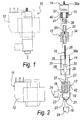
- a flow-rate adjustment valve for fluids, particularly refrigeration fluids, is generally designated by the reference numeral 10.
- the valve 10 is servoactuated by means of an electric motor 11, a stator component of which is designated by the reference numeral 12.
- a rotor component 13 of the electric motor 11 is contained within a hermetic enclosure capsule 14 and is supported so that it can rotate by virtue of means 15 for reducing rotational friction.
- the rotor component 13 has a screw-and-nut coupling with a flow control element 16.
- the flow control element 16 is retained so as to perform only axial translational motions in a valve body 17.
- the valve body 17 is provided with intake and discharge ports 18 and is fixed coaxially to the capsule 14.
- the valve body 17 is constituted by a tubular cup 19 formed by drawing.
- the resulting valve body 17 is shaped so as to accommodate a guiding element 20 for the flow control element 16.
- a cylindrical portion 21 that is coaxial to the cup 19 and is provided with a passage 22 for the flow of the fluid is formed on the bottom of the cup 19.
- the flow control element 16 engages in the opening 22, which forms one of the ports 18, so as to adjust the flow-rate of fluid.
- a hole 23 is formed in the tubular cup 19 and forms another one of the ports 18, also for the flow of the fluid.
- the flow control element 16 is constituted by a stem 25 with a threaded shank 26 and a needle-shaped opposite flow control end 27.
- the stem 25 has a rotation-preventing alignment block 28 overmolded thereon in an intermediate position.
- the block 28 is constituted by a cylinder 29 with a prism-shaped upper portion 30.
- a gasket is conveniently provided on the stem 25, below and adjacent to the block 28, and is capable of ensuring the hydraulic tightness of the valve in the fully closed position.
- Such gasket therefore allows to avoid the expensive fitting of other devices, for example a solenoid valve, suitable to provide the same hydraulic sealing function.
- the prism-like portion 30 of the block 28 engages its edges 31 in the grooves 32 of the guiding element 20, while the cylinder 29 follows the vertical sliding, ensuring minimal hunting for the flow control element 16.
- the guiding element 20 is provided by a turned, broached and drilled hexagonal bar segment.
- the element 20 thus machined is then forced inside the cup 19.
- the rotor component 13 is constituted by a female thread 33 for coupling to the threaded shank 26.
- the female thread 33 is obtained by casting.
- a cylindrical element 34 made of plastoferrite is overmolded on the female thread 33.
- the cylindrical element 34 has an annular guiding and abutment groove 35 for elastic counterthrust means 36 for the means 15 for reducing rotational friction.
- the elastic counterthrust means 36 are constituted by a helical spring.
- the means 15 for reducing rotational friction are constituted by a bearing 37 with two rings of balls.
- the enclosure capsule 14 is provided by a tubular portion 38 that is closed in an upper region by a cap-like portion 39.
- tubular portion 38 and the cap-like portion 39 are constituted respectively by a second tube 38a formed by drawing and by a cap 39a formed by drawing, as shown in Figure 2.
- tubular portion 38 and the cap-like portion 39 are constituted by a single part obtained by deep casting.
- the tube 38 and the cap 39 both abut against an abutment rim 40 that surrounds peripherally the cage 41 of the bearing 37.
- the tube 38 and the cap 39 are sealed at the rim 40 by laser welding.
- the tube 38 by resting against an abutment step 42 with which the upper edge of the cup 19 is provided, is welded to the cup 19 of the valve body 17.
- the intake and discharge tubes 24, obtained by drawing, are inserted in the cylindrical portion 21 and in the hole 23 and are also sealed by laser welding.
- the present invention provides a valve whose components are obtained to a large extent by drawing and casting, with a considerable reduction in production costs.
- the materials employed may be any according to requirements and to the state of the art.
Landscapes
- Engineering & Computer Science (AREA)
- General Engineering & Computer Science (AREA)
- Mechanical Engineering (AREA)
- Physics & Mathematics (AREA)
- Automation & Control Theory (AREA)
- General Physics & Mathematics (AREA)
- Thermal Sciences (AREA)
- Electrically Driven Valve-Operating Means (AREA)
- Lift Valve (AREA)
- Temperature-Responsive Valves (AREA)
- Compression-Type Refrigeration Machines With Reversible Cycles (AREA)
- Safety Valves (AREA)
- Nozzles (AREA)
Applications Claiming Priority (2)
| Application Number | Priority Date | Filing Date | Title |
|---|---|---|---|
| IT000027U ITPD20030027U1 (it) | 2003-03-25 | 2003-03-25 | Struttura di valvola per la regolazione della portata per fluidi in pa rticolare frigoriferi. |
| ITPD20030027U | 2003-03-25 |
Publications (3)
| Publication Number | Publication Date |
|---|---|
| EP1473496A2 true EP1473496A2 (fr) | 2004-11-03 |
| EP1473496A3 EP1473496A3 (fr) | 2004-11-24 |
| EP1473496B1 EP1473496B1 (fr) | 2006-05-17 |
Family
ID=32983229
Family Applications (1)
| Application Number | Title | Priority Date | Filing Date |
|---|---|---|---|
| EP04006989A Expired - Lifetime EP1473496B1 (fr) | 2003-03-25 | 2004-03-23 | Soupape à moteur électrique pour l'ajustage du débit de fluide, en particulier de fluide de refroidissement |
Country Status (7)
| Country | Link |
|---|---|
| US (1) | US20040188650A1 (fr) |
| EP (1) | EP1473496B1 (fr) |
| AT (1) | ATE326657T1 (fr) |
| DE (1) | DE602004000886T2 (fr) |
| DK (1) | DK1473496T3 (fr) |
| IT (1) | ITPD20030027U1 (fr) |
| NO (1) | NO20041230L (fr) |
Cited By (3)
| Publication number | Priority date | Publication date | Assignee | Title |
|---|---|---|---|---|
| EP1777447A2 (fr) | 2005-10-20 | 2007-04-25 | Carel S.p.A. | Vanne |
| WO2011059677A1 (fr) * | 2009-11-13 | 2011-05-19 | Fisher Controls International Llc | Appareil d'accouplement destiné à être utilisé avec des actionneurs électriques |
| US8979063B2 (en) | 2011-11-28 | 2015-03-17 | Fisher Controls International Llc | Failsafe apparatus for use with linear actuators |
Families Citing this family (8)
| Publication number | Priority date | Publication date | Assignee | Title |
|---|---|---|---|---|
| JP5643261B2 (ja) * | 2011-12-07 | 2014-12-17 | 株式会社鷺宮製作所 | 雌ネジ部材をインサート成形によって一体化するインサート成形方法 |
| DE102013012029A1 (de) * | 2013-07-19 | 2015-01-22 | Honeywell Technologies Sarl | Elektronisches Expansionsventil |
| US9657656B2 (en) * | 2014-08-27 | 2017-05-23 | Continental Automotive Systems, Inc. | Idle air control valve for use in a small engine and having a protective shroud with valve seat |
| CN108702122B (zh) * | 2015-10-29 | 2022-06-21 | 超级高铁技术公司 | 变频驱动系统 |
| CN108692042A (zh) * | 2017-04-12 | 2018-10-23 | 杭州三花研究院有限公司 | 电子膨胀阀 |
| CN112901803B (zh) * | 2019-11-19 | 2022-05-13 | 浙江盾安禾田金属有限公司 | 电子膨胀阀 |
| JP7653385B2 (ja) * | 2022-03-29 | 2025-03-28 | 株式会社鷺宮製作所 | 弁装置および冷凍サイクルシステム |
| DE102024118407A1 (de) * | 2024-06-28 | 2025-12-31 | ECO Holding 1 GmbH | Ventilbaugruppe für Kältemittel, Fahrzeugkältemittelsystem mit einer solchen Ventilbaugruppe und Herstellungsverfahren |
Family Cites Families (10)
| Publication number | Priority date | Publication date | Assignee | Title |
|---|---|---|---|---|
| US2956188A (en) * | 1956-04-06 | 1960-10-11 | Fostoria Corp | Sealless motor for valve operation |
| ATE51281T1 (de) * | 1983-01-21 | 1990-04-15 | Fuji Kinzoku Kosaku Kk | Regelventil. |
| JPH0249432B2 (ja) * | 1983-09-26 | 1990-10-30 | Taiheiyo Kogyo Kk | Dendobennobenjikukaitentomeichinochoseihoho |
| JPS6347579A (ja) * | 1986-08-14 | 1988-02-29 | Toyo Eng Corp | 弁 |
| JPS6435185A (en) * | 1987-07-30 | 1989-02-06 | Fuji Photo Film Co Ltd | Flow control valve |
| US5364066A (en) * | 1993-07-15 | 1994-11-15 | Sporlan Valve Company | Dual port valve with stepper motor actuator |
| CA2121067C (fr) * | 1993-09-27 | 1997-11-11 | William E. Hoehn | Vanne pour circuit de fluide |
| ITPD980036A1 (it) * | 1998-02-23 | 1999-08-23 | Luigi Nalini | Valvola di regolazione di portata per fluidi in particolare frigorifer i, servoazionata con un motore elettrico |
| JP3937029B2 (ja) * | 1999-03-26 | 2007-06-27 | 株式会社鷺宮製作所 | 電動弁 |
| JP2005048779A (ja) * | 2001-09-11 | 2005-02-24 | Chiyoda Kucho Kiki Kk | コントロールバルブ |
-
2003
- 2003-03-25 IT IT000027U patent/ITPD20030027U1/it unknown
-
2004
- 2004-03-22 US US10/805,189 patent/US20040188650A1/en not_active Abandoned
- 2004-03-23 EP EP04006989A patent/EP1473496B1/fr not_active Expired - Lifetime
- 2004-03-23 DE DE602004000886T patent/DE602004000886T2/de not_active Expired - Lifetime
- 2004-03-23 DK DK04006989T patent/DK1473496T3/da active
- 2004-03-23 AT AT04006989T patent/ATE326657T1/de not_active IP Right Cessation
- 2004-03-24 NO NO20041230A patent/NO20041230L/no not_active Application Discontinuation
Cited By (9)
| Publication number | Priority date | Publication date | Assignee | Title |
|---|---|---|---|---|
| EP1777447A2 (fr) | 2005-10-20 | 2007-04-25 | Carel S.p.A. | Vanne |
| EP1777447A3 (fr) * | 2005-10-20 | 2007-11-21 | Carel S.p.A. | Vanne |
| US7871059B2 (en) | 2005-10-20 | 2011-01-18 | Carel S.P.A. | Valve for adjusting the flow-rate of fluids, particularly refrigeration fluids |
| WO2011059677A1 (fr) * | 2009-11-13 | 2011-05-19 | Fisher Controls International Llc | Appareil d'accouplement destiné à être utilisé avec des actionneurs électriques |
| CN102656395A (zh) * | 2009-11-13 | 2012-09-05 | 费希尔控制国际公司 | 用于电致动器的耦接装置 |
| US8636262B2 (en) | 2009-11-13 | 2014-01-28 | Fisher Controls International, Llc | Coupling apparatus for use with electric actuators |
| CN102656395B (zh) * | 2009-11-13 | 2014-12-17 | 费希尔控制国际公司 | 用于电致动器的耦接装置 |
| RU2562346C2 (ru) * | 2009-11-13 | 2015-09-10 | Фишер Контролз Интернешнел Ллс | Соединительное устройство для использования с электрическими приводами |
| US8979063B2 (en) | 2011-11-28 | 2015-03-17 | Fisher Controls International Llc | Failsafe apparatus for use with linear actuators |
Also Published As
| Publication number | Publication date |
|---|---|
| EP1473496B1 (fr) | 2006-05-17 |
| EP1473496A3 (fr) | 2004-11-24 |
| DE602004000886D1 (de) | 2006-06-22 |
| ITPD20030027U1 (it) | 2004-09-26 |
| NO20041230L (no) | 2004-09-27 |
| DK1473496T3 (da) | 2006-09-18 |
| ATE326657T1 (de) | 2006-06-15 |
| US20040188650A1 (en) | 2004-09-30 |
| DE602004000886T2 (de) | 2006-12-07 |
Similar Documents
| Publication | Publication Date | Title |
|---|---|---|
| EP3336396B1 (fr) | Soupape de détente électronique | |
| EP1473496B1 (fr) | Soupape à moteur électrique pour l'ajustage du débit de fluide, en particulier de fluide de refroidissement | |
| JP7058744B2 (ja) | 電子膨張弁 | |
| JP3145048U (ja) | 電動膨張弁及び冷凍サイクル | |
| CN109219716B (zh) | 电动阀 | |
| US5502874A (en) | Speed regulating valve for fluid filled door closers | |
| US12104709B2 (en) | Electric valve | |
| EP0937928A1 (fr) | Soupape de réglage actionnée par moteur électrique | |
| CN101622487A (zh) | 回转楔形插装阀机构以及组装和拆卸方法 | |
| CN112324947A (zh) | 一种旋转式换向阀 | |
| US9140469B2 (en) | Refrigeration valve block | |
| CN112361671A (zh) | 一种带有硬密封结构的电磁阀 | |
| CN220488423U (zh) | 电磁阀 | |
| KR20080086878A (ko) | 폐쇄 밸브 및 공기 조화기 | |
| CN214743672U (zh) | 电动阀以及冷冻循环系统 | |
| US3633870A (en) | Water regulating valve | |
| CN213841418U (zh) | 一种带有硬密封结构的电磁阀 | |
| CN110274047A (zh) | 一种按压式磁控锁阀 | |
| CN107178621A (zh) | 一种制冷系统用截止阀及其阀杆 | |
| CN216200549U (zh) | 可视型手动无菌取样阀 | |
| US20150136258A1 (en) | Spool assembly and a valve comprising the same | |
| CN110822109B (zh) | 阀装置 | |
| CN112128408A (zh) | 流体管理组件 | |
| CN224017724U (zh) | 截止阀 | |
| CN218913911U (zh) | 插装式液压阀用电磁铁 |
Legal Events
| Date | Code | Title | Description |
|---|---|---|---|
| PUAI | Public reference made under article 153(3) epc to a published international application that has entered the european phase |
Free format text: ORIGINAL CODE: 0009012 |
|
| PUAL | Search report despatched |
Free format text: ORIGINAL CODE: 0009013 |
|
| AK | Designated contracting states |
Kind code of ref document: A2 Designated state(s): AT BE BG CH CY CZ DE DK EE ES FI FR GB GR HU IE IT LI LU MC NL PL PT RO SE SI SK TR |
|
| AX | Request for extension of the european patent |
Extension state: AL LT LV MK |
|
| AK | Designated contracting states |
Kind code of ref document: A3 Designated state(s): AT BE BG CH CY CZ DE DK EE ES FI FR GB GR HU IE IT LI LU MC NL PL PT RO SE SI SK TR |
|
| AX | Request for extension of the european patent |
Extension state: AL LT LV MK |
|
| 17P | Request for examination filed |
Effective date: 20050412 |
|
| AKX | Designation fees paid |
Designated state(s): AT BE BG CH CY CZ DE DK EE ES FI FR GB GR HU IE IT LI LU MC NL PL PT RO SE SI SK TR |
|
| GRAP | Despatch of communication of intention to grant a patent |
Free format text: ORIGINAL CODE: EPIDOSNIGR1 |
|
| GRAS | Grant fee paid |
Free format text: ORIGINAL CODE: EPIDOSNIGR3 |
|
| GRAA | (expected) grant |
Free format text: ORIGINAL CODE: 0009210 |
|
| AK | Designated contracting states |
Kind code of ref document: B1 Designated state(s): AT BE BG CH CY CZ DE DK EE ES FI FR GB GR HU IE IT LI LU MC NL PL PT RO SE SI SK TR |
|
| PG25 | Lapsed in a contracting state [announced via postgrant information from national office to epo] |
Ref country code: BE Free format text: LAPSE BECAUSE OF FAILURE TO SUBMIT A TRANSLATION OF THE DESCRIPTION OR TO PAY THE FEE WITHIN THE PRESCRIBED TIME-LIMIT Effective date: 20060517 Ref country code: IT Free format text: LAPSE BECAUSE OF FAILURE TO SUBMIT A TRANSLATION OF THE DESCRIPTION OR TO PAY THE FEE WITHIN THE PRESCRIBED TIME-LIMIT;WARNING: LAPSES OF ITALIAN PATENTS WITH EFFECTIVE DATE BEFORE 2007 MAY HAVE OCCURRED AT ANY TIME BEFORE 2007. THE CORRECT EFFECTIVE DATE MAY BE DIFFERENT FROM THE ONE RECORDED. Effective date: 20060517 Ref country code: LI Free format text: LAPSE BECAUSE OF FAILURE TO SUBMIT A TRANSLATION OF THE DESCRIPTION OR TO PAY THE FEE WITHIN THE PRESCRIBED TIME-LIMIT Effective date: 20060517 Ref country code: AT Free format text: LAPSE BECAUSE OF FAILURE TO SUBMIT A TRANSLATION OF THE DESCRIPTION OR TO PAY THE FEE WITHIN THE PRESCRIBED TIME-LIMIT Effective date: 20060517 Ref country code: CZ Free format text: LAPSE BECAUSE OF FAILURE TO SUBMIT A TRANSLATION OF THE DESCRIPTION OR TO PAY THE FEE WITHIN THE PRESCRIBED TIME-LIMIT Effective date: 20060517 Ref country code: FI Free format text: LAPSE BECAUSE OF FAILURE TO SUBMIT A TRANSLATION OF THE DESCRIPTION OR TO PAY THE FEE WITHIN THE PRESCRIBED TIME-LIMIT Effective date: 20060517 Ref country code: PL Free format text: LAPSE BECAUSE OF FAILURE TO SUBMIT A TRANSLATION OF THE DESCRIPTION OR TO PAY THE FEE WITHIN THE PRESCRIBED TIME-LIMIT Effective date: 20060517 Ref country code: RO Free format text: LAPSE BECAUSE OF FAILURE TO SUBMIT A TRANSLATION OF THE DESCRIPTION OR TO PAY THE FEE WITHIN THE PRESCRIBED TIME-LIMIT Effective date: 20060517 Ref country code: NL Free format text: LAPSE BECAUSE OF FAILURE TO SUBMIT A TRANSLATION OF THE DESCRIPTION OR TO PAY THE FEE WITHIN THE PRESCRIBED TIME-LIMIT Effective date: 20060517 Ref country code: SI Free format text: LAPSE BECAUSE OF FAILURE TO SUBMIT A TRANSLATION OF THE DESCRIPTION OR TO PAY THE FEE WITHIN THE PRESCRIBED TIME-LIMIT Effective date: 20060517 Ref country code: SK Free format text: LAPSE BECAUSE OF FAILURE TO SUBMIT A TRANSLATION OF THE DESCRIPTION OR TO PAY THE FEE WITHIN THE PRESCRIBED TIME-LIMIT Effective date: 20060517 Ref country code: CH Free format text: LAPSE BECAUSE OF FAILURE TO SUBMIT A TRANSLATION OF THE DESCRIPTION OR TO PAY THE FEE WITHIN THE PRESCRIBED TIME-LIMIT Effective date: 20060517 |
|
| REG | Reference to a national code |
Ref country code: GB Ref legal event code: FG4D |
|
| REG | Reference to a national code |
Ref country code: SE Ref legal event code: TRGR |
|
| REG | Reference to a national code |
Ref country code: CH Ref legal event code: EP |
|
| REG | Reference to a national code |
Ref country code: IE Ref legal event code: FG4D |
|
| REF | Corresponds to: |
Ref document number: 602004000886 Country of ref document: DE Date of ref document: 20060622 Kind code of ref document: P |
|
| PG25 | Lapsed in a contracting state [announced via postgrant information from national office to epo] |
Ref country code: ES Free format text: LAPSE BECAUSE OF FAILURE TO SUBMIT A TRANSLATION OF THE DESCRIPTION OR TO PAY THE FEE WITHIN THE PRESCRIBED TIME-LIMIT Effective date: 20060828 |
|
| REG | Reference to a national code |
Ref country code: DK Ref legal event code: T3 |
|
| PG25 | Lapsed in a contracting state [announced via postgrant information from national office to epo] |
Ref country code: PT Free format text: LAPSE BECAUSE OF FAILURE TO SUBMIT A TRANSLATION OF THE DESCRIPTION OR TO PAY THE FEE WITHIN THE PRESCRIBED TIME-LIMIT Effective date: 20061017 |
|
| ET | Fr: translation filed | ||
| NLV1 | Nl: lapsed or annulled due to failure to fulfill the requirements of art. 29p and 29m of the patents act | ||
| REG | Reference to a national code |
Ref country code: CH Ref legal event code: PL |
|
| PLBE | No opposition filed within time limit |
Free format text: ORIGINAL CODE: 0009261 |
|
| STAA | Information on the status of an ep patent application or granted ep patent |
Free format text: STATUS: NO OPPOSITION FILED WITHIN TIME LIMIT |
|
| 26N | No opposition filed |
Effective date: 20070220 |
|
| PG25 | Lapsed in a contracting state [announced via postgrant information from national office to epo] |
Ref country code: IE Free format text: LAPSE BECAUSE OF NON-PAYMENT OF DUE FEES Effective date: 20070323 Ref country code: MC Free format text: LAPSE BECAUSE OF NON-PAYMENT OF DUE FEES Effective date: 20070331 |
|
| PG25 | Lapsed in a contracting state [announced via postgrant information from national office to epo] |
Ref country code: GR Free format text: LAPSE BECAUSE OF FAILURE TO SUBMIT A TRANSLATION OF THE DESCRIPTION OR TO PAY THE FEE WITHIN THE PRESCRIBED TIME-LIMIT Effective date: 20060818 |
|
| PG25 | Lapsed in a contracting state [announced via postgrant information from national office to epo] |
Ref country code: BG Free format text: LAPSE BECAUSE OF FAILURE TO SUBMIT A TRANSLATION OF THE DESCRIPTION OR TO PAY THE FEE WITHIN THE PRESCRIBED TIME-LIMIT Effective date: 20060817 |
|
| PG25 | Lapsed in a contracting state [announced via postgrant information from national office to epo] |
Ref country code: EE Free format text: LAPSE BECAUSE OF FAILURE TO SUBMIT A TRANSLATION OF THE DESCRIPTION OR TO PAY THE FEE WITHIN THE PRESCRIBED TIME-LIMIT Effective date: 20060517 |
|
| PG25 | Lapsed in a contracting state [announced via postgrant information from national office to epo] |
Ref country code: CY Free format text: LAPSE BECAUSE OF FAILURE TO SUBMIT A TRANSLATION OF THE DESCRIPTION OR TO PAY THE FEE WITHIN THE PRESCRIBED TIME-LIMIT Effective date: 20060517 Ref country code: LU Free format text: LAPSE BECAUSE OF NON-PAYMENT OF DUE FEES Effective date: 20070323 |
|
| PG25 | Lapsed in a contracting state [announced via postgrant information from national office to epo] |
Ref country code: HU Free format text: LAPSE BECAUSE OF FAILURE TO SUBMIT A TRANSLATION OF THE DESCRIPTION OR TO PAY THE FEE WITHIN THE PRESCRIBED TIME-LIMIT Effective date: 20061118 Ref country code: TR Free format text: LAPSE BECAUSE OF FAILURE TO SUBMIT A TRANSLATION OF THE DESCRIPTION OR TO PAY THE FEE WITHIN THE PRESCRIBED TIME-LIMIT Effective date: 20060517 |
|
| PGFP | Annual fee paid to national office [announced via postgrant information from national office to epo] |
Ref country code: SE Payment date: 20130322 Year of fee payment: 10 |
|
| REG | Reference to a national code |
Ref country code: SE Ref legal event code: EUG |
|
| PG25 | Lapsed in a contracting state [announced via postgrant information from national office to epo] |
Ref country code: SE Free format text: LAPSE BECAUSE OF NON-PAYMENT OF DUE FEES Effective date: 20140324 |
|
| REG | Reference to a national code |
Ref country code: FR Ref legal event code: PLFP Year of fee payment: 13 |
|
| PGFP | Annual fee paid to national office [announced via postgrant information from national office to epo] |
Ref country code: DE Payment date: 20160310 Year of fee payment: 13 Ref country code: IT Payment date: 20160223 Year of fee payment: 13 Ref country code: DK Payment date: 20160318 Year of fee payment: 13 |
|
| PGFP | Annual fee paid to national office [announced via postgrant information from national office to epo] |
Ref country code: GB Payment date: 20160219 Year of fee payment: 13 Ref country code: FR Payment date: 20160310 Year of fee payment: 13 |
|
| REG | Reference to a national code |
Ref country code: DE Ref legal event code: R119 Ref document number: 602004000886 Country of ref document: DE |
|
| REG | Reference to a national code |
Ref country code: DK Ref legal event code: EBP Effective date: 20170331 |
|
| GBPC | Gb: european patent ceased through non-payment of renewal fee |
Effective date: 20170323 |
|
| REG | Reference to a national code |
Ref country code: FR Ref legal event code: ST Effective date: 20171130 |
|
| PG25 | Lapsed in a contracting state [announced via postgrant information from national office to epo] |
Ref country code: FR Free format text: LAPSE BECAUSE OF NON-PAYMENT OF DUE FEES Effective date: 20170331 Ref country code: DE Free format text: LAPSE BECAUSE OF NON-PAYMENT OF DUE FEES Effective date: 20171003 |
|
| PG25 | Lapsed in a contracting state [announced via postgrant information from national office to epo] |
Ref country code: GB Free format text: LAPSE BECAUSE OF NON-PAYMENT OF DUE FEES Effective date: 20170323 Ref country code: IT Free format text: LAPSE BECAUSE OF NON-PAYMENT OF DUE FEES Effective date: 20170323 |
|
| PG25 | Lapsed in a contracting state [announced via postgrant information from national office to epo] |
Ref country code: DK Free format text: LAPSE BECAUSE OF NON-PAYMENT OF DUE FEES Effective date: 20170331 |