EP1473541A2 - Linienerzeugungsvorrichtung - Google Patents
Linienerzeugungsvorrichtung Download PDFInfo
- Publication number
- EP1473541A2 EP1473541A2 EP04009822A EP04009822A EP1473541A2 EP 1473541 A2 EP1473541 A2 EP 1473541A2 EP 04009822 A EP04009822 A EP 04009822A EP 04009822 A EP04009822 A EP 04009822A EP 1473541 A2 EP1473541 A2 EP 1473541A2
- Authority
- EP
- European Patent Office
- Prior art keywords
- pin
- assembly
- disposed
- legs
- housing
- Prior art date
- Legal status (The legal status is an assumption and is not a legal conclusion. Google has not performed a legal analysis and makes no representation as to the accuracy of the status listed.)
- Withdrawn
Links
Images
Classifications
-
- G—PHYSICS
- G01—MEASURING; TESTING
- G01C—MEASURING DISTANCES, LEVELS OR BEARINGS; SURVEYING; NAVIGATION; GYROSCOPIC INSTRUMENTS; PHOTOGRAMMETRY OR VIDEOGRAMMETRY
- G01C15/00—Surveying instruments or accessories not provided for in groups G01C1/00 - G01C13/00
- G01C15/002—Active optical surveying means
- G01C15/004—Reference lines, planes or sectors
-
- G—PHYSICS
- G01—MEASURING; TESTING
- G01C—MEASURING DISTANCES, LEVELS OR BEARINGS; SURVEYING; NAVIGATION; GYROSCOPIC INSTRUMENTS; PHOTOGRAMMETRY OR VIDEOGRAMMETRY
- G01C15/00—Surveying instruments or accessories not provided for in groups G01C1/00 - G01C13/00
- G01C15/002—Active optical surveying means
- G01C15/008—Active optical surveying means combined with inclination sensor
Definitions
- the present invention generally relates to line generating devices and more specifically to laser line generating devices.
- an improved line generating device may include a housing, a support assembly mounted within the housing, a light source mounted on the support assembly, a lens mounted on at least one of the support assembly and the light source, the lens receiving light and projecting the light in the shape of a fan within a plane, and a first level vial mounted on the support assembly, wherein the first level vial is coplanar or perpendicular to the plane.
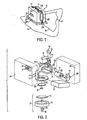
- Line generating device 10 may comprise a frame assembly 11, a diode assembly 12, a lens 13 mounted onto the diode barrel 12, level vials 16, 17 mounted on frame assembly 11, printed circuit board 20, with a switch 21 mounted thereon, battery B received on the frame assembly 11, a switch actuator 25 for actuating switch 21, and a housing 22 for receiving for enclosing most, if not all, of the elements described above.
- Frame assembly 11 is preferably made of metal, such as magnesium or zinc.
- Frame assembly 11 preferably has a substantially horizontal planar support 11C, a substantially vertical post 11P connected to planar support 11C, and support section 11S for receiving and/or supporting several components.
- support portion 11S receives and supports diode assembly 12 and/or level vials 16, 17.
- Battery B may be disposed between planar support 11C and support portion 11S. Battery B may be a 9 volt battery.
- diode assembly 12 may be disposed into support portion 11S.
- diode assembly 12 has a laser diode (not shown) and/or a collimating lens (not shown).
- the laser diode and/or the collimating lens may be disposed in a barrel 12B.
- a projection lens 13 may be disposed in front of the laser diode and/or the diode assembly 12.
- lens 13 is substantially cylindrical, so that it can receives the light from the laser diode and project it in the shape of a fan.
- Barrel 12B may have slots 12S for receiving pins 13P protruding from cylindrical lens 13.
- cylindrical lens 13 may be mounted unto barrel 12B and/or support portion 11S using other means.
- the diode assembly 12 and the cylindrical lens 13 will generate a laser light plane LP which, will generate a laser line LL on a surface S, as shown in FIG. 1.
- the diode assembly 12 and cylindrical lens 13 are received within the support portion 11S of frame assembly 11. It is preferable to provide a means for adjusting the diode assembly 12 relative to frame assembly 11.
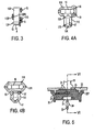
- One such mechanism includes a spring 14, which is preferably captured between barrel 12B and support portion 11S, a set screw 15 threadingly engaged to support portion 11S, and pivot portion 11 SP formed by part of the support portion 11S disposed between the spring 14 and set screw 15. It may be preferable to dispose a slot 12BS on barrel 12B to engage the pivot portion 11 SP.
- barrel 12B when the set screw 15 is rotated, barrel 12B will preferably pivot about the pivot portion 11SP. If set screw 15 is rotated in the other direction, spring 14 will cause rotation of the barrel 12B about pivot portion 11SP.
- Rapid cure adhesive may work well for such application.
- level vials 16, 17 are provided on line generating device 10.
- Level vial 16 is preferably disposed on frame assembly 11 so that, when line generating device 10 is substantially vertically on a vertical wall, level vial 16 will show the degree of verticality of line generating device 10.
- level vial 17 will be disposed on frame assembly 11 so that, when the line generating device 10 is disposed substantially horizontally against a vertical wall, level vial 17 will show the degree of horizontality of line generating device 10. It is thus preferable to adjust the level vials 16, 17 relative to the laser plane LP so that level vials 16, 17 will provide an accurate reading thereof.
- level vial 17 it is preferable to dispose level vial 17 on support portion 11S.
- level vial 17 will be captured between ribs 11R on support portion 11S.
- one end of level vial 16 may be captured within ribs of 11R disposed on support portion 11S.
- a ramp screw head 18 which threadingly engages support portion 11S and contacts the other end of level vial 16.
- a compression plug 19 On the other side of level vial 16, it is preferable to provide a compression plug 19. Accordingly, by rotating ramp screw head 18, the level vial 16 can be rotated to the appropriate position.
- FIG. 4B illustrates a different method of adjusting level vials 16, 17.
- level vial 16 is captured between ribs 11R on support portion 11S.
- Level vial 17 is captured at one end by ribs 11R as well.
- the set screw 18' is threadingly engaged to support portion 11S and contacts one side of level vial 17.
- Compression plug 19 is disposed on the other side of level vial 17. Accordingly, the level vial 17 can be adjusted by rotating set screw 18'.
- level vial 16, 17 unto support portion 11S with potting adhesive. Further ribs can be added if necessary.
- level vial 17 is preferably fixed on frame assembly 11, barrel 12B is then adjusted and locked relative to level vial 17, and level vial 16 is adjusted and locked relative to barrel 12B and/or the laser plane LP.
- level vial 16 may be fixed on frame assembly 11, barrel 12B is then adjusted and locked relative to level vial 16, and level vial 17 is adjusted and locked relative to barrel 12B and/or the laser plane LP. Preferably, such adjustments will be conducted when device 10 is placed on a substantially vertical surface.
- housing 22 preferably comprises two clamshell halves which define an opening 220 for allowing the laser light plane LP to exit from housing 22.
- housing 22 may have openings such as 170 for allowing the user to see the level vial 16, 17.
- the edge of the openings are such as 170E are beveled or inclined to maximize this ability of the level vial 16 and/or 17.
- Housing 22 may have a reference indicia 22R, which is preferably coplanar with light plane LP.
- any electronics necessary to power the laser diode are preferably disposed on printed circuit board 20.
- a switch 21 may be disposed on the printed circuit board 20 for controlling the flow of power to the laser diode.
- a switch actuator 25 may be disposed on housing 22 for actuating switch 21, allowing the user to turn the laser diode (and thus the line generating device 10) on and/or off.
- a magnet 24 may be placed and glued onto a magnet holder 23, which is preferably disposed on the planar support 11C of frame assembly 11.
- housing 22 does not cover magnet 24.
- providing magnet 24 will enable the user to dispose device 10 onto a ferrous surface, etc.
- pin assembly 30 may include a body 31, a metal plate 32 disposed in body 31 and a pin 33 connected to body 31.
- pin 33 is attached to pivoting body 35, which is in turn pivotally attached to body 31. With such construction, pin 33 can be extended into a position where it can be inserted into drywall or retracted into a folded position within main body 31, as shown in FIG. 6 in solid and broken lines, respectively.
- pivoting body 35 and body 31 will have a small protrusion (not shown) engaging a hole or notch (not shown) in the other of the pivoting body 35 and body 31, in effect providing a detent for maintaining the pin 33 in the extended and/or retracted positions.
- a detent for maintaining the pin 33 in the extended and/or retracted positions.
- Persons skilled in the art will know how to design such detent so that it maintains the pin 33 in the extended position when the user is inserting pin 33 into drywall.
- Persons skilled in the art will also know how to design such detent so that it allows pin 33 to move into the folded position when pin assembly 30 is dropped unto the floor, etc.
- Housing 22 may have flanges 22F which engage the inside of main body 31.
- pin assembly 30 may be disposed on housing 22 and held in place via the magnetic relationship between magnet 24 and metal plate 32.
- magnet 24 may be disposed on the pin assembly 30 and metal plate may be disposed on housing 22.
- the user can dispose line generating device on a wall by inserting pin assembly 30 into the wall and then disposing line generating device 10 on pin assembly 30. It may be preferable to provide a flat portion 34 on pin 33 to prevent the pin 33 (and thus pin assembly 30) from rotating when inserted into drywall, etc.
- pin 33 be coplanar with laser light plane LP.
- reference indicia 22R will also be coplanar with pin 33.
- housing 22 may have reference indicia 22PR which is coplanar with pin 33 along a plane which is substantially perpendicular with laser light plane LP.
- friction means on the wall side of main body 31 to reduce the chance of rotation of main body 31 relative to the wall.
- friction means could include rubber buttons, adhesive disks etc.
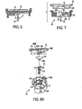
- FIG. 7 illustrates another embodiment of the pin assembly 30, where like numbers refer to like parts. Persons skilled in the art will recognize that the teachings of the previous embodiment are hereby incorporated by reference.
- pin assembly 30 may include a body 31 and a pin 33 connected to body 31.
- pin 33 is attached to pivoting body 35, which is in turn pivotally attached to body 31.
- pin 33 can be extended into a position where it can be inserted into drywall or retracted into a folded position within main body 31, as shown in FIG. 7 in solid and broken lines, respectively.
- Pivoting body 35 may be made of a ferrous material, so that it can be attracted by magnet 24, and thus pin assembly 30 is magnetically attached to device 10. Pivoting body 35 may also have a surface 35S, which contacts ledge 31L of body 31, to limit the angular movement range of pivoting body 35. Persons skilled in the art will recognize that it is preferable to ensure that surface 35S and ledge 31L contact when pin 33 is extended in the desired position.
- Pivoting body 35 may also have a surface 35F which, when pin 33 is in the folded position, is adjacent and/or contacting magnet 24. This allows the user to maintain pin assembly 30 on device 10 even when pin 33 is in the folded position.
- Pin assembly 30 may also have a magnet 37 on body 31.
- Pin 33 is preferably made of a ferrous material, and thus can be attracted to magnet 37. Accordingly, magnet 37 can maintain pin 33 in the folded position.
- device 10 can also be disposed on a wall mounting assembly 40.
- wall mounting assembly 40 includes a main body 41.
- Main body 41 may receive at least two (preferably three) L-shaped legs 42, which would extend through a hole 41H in main body 41.
- a coil spring or collar 43 preferably maintains legs 42 together.
- Main body 41 may have posts 41P and/or slots 41S in walls 41C, which receive legs 42 and prevent legs 42 from rotating about hole 41H.
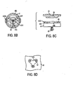
- Wall mounting assembly 40 may also include a cam ring 45.
- Cam ring 45 may have at least two (preferably three) inclined slots 45S, which each slot 45S receiving one leg 42.
- Cam ring 45 may also have a plate 44.
- Plate 44 is preferably made of a ferrous material, so that it can be attracted to magnet 24, thus keeping wall mounting assembly 40 in contact with device 10.
- Plate 44 may also have a substantially spherical portion 44S, which preferably contacts the bends of legs 42. Persons skilled in the art will recognize that spherical portion 44 need not be integral to plate 44 and can thus be a separate element, such as a ball.
- Cam ring 45 is preferably disposed unto main body 41. Accordingly, cam ring 45 may have a ledge 45L which is engaged by hooks 41SH of main body 41 for retaining cam ring 45. Preferably, hooks 41 are relatively resilient so that they act as snap hooks. Persons skilled in the art will recognize that ledge 45L and hooks 41SH could also be disposed on main body 41 and cam ring 45, respectively.
- Cam ring 45 may also have at least one knob 45K to allow the user to rotate cam ring 45 relative to main body 41.
- cam ring 45 can be rotated to move legs 42 from a retracted position (shown in solid lines in FIG. 8C) to an expanded position (shown in broken lines in FIG. 8C). This would allow the user to drill a hole in a wall, install the wall mounting assembly 40 unto the wall, and dispose device 10 unto wall mounting assembly 40 for operation. Due to the expanding movement of legs 42, the dimensions of the hole is not critical.
- the inclined slots 45S lift the legs 42 in an axial direction.
- the legs 42 move along inclined slots and towards spherical portion 44S.
- Spherical portion 44S in turn provides a central force at or near the bends of legs 42. The force is provided equally to each leg 42. Because legs 42 cannot rotate about the axial direction due to the posts 41P and/or slots 41 S, legs 42 rotate towards the expanded position. As torque on the cam ring 45 is increased, the gripping force of legs 42 in the expanded position is increased.
- the user need only rotate cam ring 45 in the opposite direction in order to move legs 42 towards the retracted position.
- Slot 45S may be provided with protrusions 45SP along the length of each slot. These protrusions 45SP define valleys 45SV where each leg 42 can remain until leg 42 is moved over the next protrusion 45SP and towards the next valley 45SV.
- hole 41H may be designed to limit the rotational movement about the hole 41H. Accordingly, hole 41H may have slots extending from the center of the hole 41H, as shown in FIG. 8D.
- wall mounting assembly 40 may not just be mounted to a wall, but could be mounted unto other surfaces, such as a power tool housing, etc.
Landscapes
- Physics & Mathematics (AREA)
- Engineering & Computer Science (AREA)
- General Physics & Mathematics (AREA)
- Radar, Positioning & Navigation (AREA)
- Remote Sensing (AREA)
- Catching Or Destruction (AREA)
- Radiation-Therapy Devices (AREA)
- Light Guides In General And Applications Therefor (AREA)
- Adornments (AREA)
- Toys (AREA)
- Medical Preparation Storing Or Oral Administration Devices (AREA)
Applications Claiming Priority (4)
| Application Number | Priority Date | Filing Date | Title |
|---|---|---|---|
| US46668503P | 2003-04-30 | 2003-04-30 | |
| US466685P | 2003-04-30 | ||
| US46916003P | 2003-05-09 | 2003-05-09 | |
| US469160P | 2003-05-09 |
Publications (2)
| Publication Number | Publication Date |
|---|---|
| EP1473541A2 true EP1473541A2 (de) | 2004-11-03 |
| EP1473541A3 EP1473541A3 (de) | 2005-04-06 |
Family
ID=32995076
Family Applications (1)
| Application Number | Title | Priority Date | Filing Date |
|---|---|---|---|
| EP04009822A Withdrawn EP1473541A3 (de) | 2003-04-30 | 2004-04-26 | Linienerzeugungsvorrichtung |
Country Status (6)
| Country | Link |
|---|---|
| US (1) | US6931740B2 (de) |
| EP (1) | EP1473541A3 (de) |
| CN (1) | CN100559117C (de) |
| AU (1) | AU2004201652A1 (de) |
| NZ (1) | NZ532555A (de) |
| TW (1) | TW200513634A (de) |
Cited By (2)
| Publication number | Priority date | Publication date | Assignee | Title |
|---|---|---|---|---|
| CN103712633A (zh) * | 2013-12-20 | 2014-04-09 | 江苏大学 | 激光投线仪光线自动调校的方法 |
| EP3536465A1 (de) * | 2018-03-09 | 2019-09-11 | Stanley Black & Decker, Inc. | Chirurgisches laserwerkzeug |
Families Citing this family (18)
| Publication number | Priority date | Publication date | Assignee | Title |
|---|---|---|---|---|
| US6914930B2 (en) * | 2002-05-31 | 2005-07-05 | Black & Decker Inc. | Laser level |
| TWM242685U (en) * | 2003-03-04 | 2004-09-01 | Quarton Inc | Three-direction laser indicator |
| US7181853B2 (en) * | 2003-07-11 | 2007-02-27 | Zircon Corporation | Modular laser layout system |
| CN101614812B (zh) * | 2004-11-30 | 2010-12-22 | 亚洲光学股份有限公司 | 镭射尺的光轴调整机构 |
| TWI260403B (en) * | 2004-12-07 | 2006-08-21 | Asia Optical Co Inc | Optical axis adjusting device of laser ruler |
| TWI311391B (en) * | 2005-04-08 | 2009-06-21 | Quarton Inc | Laser module for projecting a linear laser beam |
| US7497019B2 (en) * | 2005-08-04 | 2009-03-03 | Irwin Industrial Tool Company | Laser reference device |
| US7328516B2 (en) | 2005-08-05 | 2008-02-12 | Irwin Industrial Tool Company | Laser level |
| US7861424B2 (en) * | 2006-11-13 | 2011-01-04 | Robert Bosch Tool Corporation | Pipe laser |
| US8269612B2 (en) | 2008-07-10 | 2012-09-18 | Black & Decker Inc. | Communication protocol for remotely controlled laser devices |
| US9908182B2 (en) | 2012-01-30 | 2018-03-06 | Black & Decker Inc. | Remote programming of a power tool |
| US20130327552A1 (en) | 2012-06-08 | 2013-12-12 | Black & Decker Inc. | Power tool having multiple operating modes |
| EP2840355A1 (de) * | 2013-08-21 | 2015-02-25 | HILTI Aktiengesellschaft | Lasergerät und Haltevorrichtung zur Befestigung eines Lasergerätes an einem Halteelement |
| US10014674B1 (en) * | 2017-07-05 | 2018-07-03 | Seeless Solutions, Inc. | Recessed wall mounting apparatus and method |
| CN108759794B (zh) * | 2018-05-14 | 2021-03-02 | 南京涵曦月自动化科技有限公司 | 多功能建筑标线灯 |
| CA3053026A1 (en) | 2018-09-07 | 2020-03-07 | Signalisation D'urgence Rh Inc. | Collapsible warning device and method for emitting a light signal |
| US11247326B2 (en) * | 2019-09-25 | 2022-02-15 | Nation Wide Products Llc | Mechanism for forming orthogonal joints in conduits |
| CN115750552A (zh) * | 2022-12-14 | 2023-03-07 | 中山卡宴摄影器材有限公司 | 一种伸缩支脚锁定装置 |
Family Cites Families (10)
| Publication number | Priority date | Publication date | Assignee | Title |
|---|---|---|---|---|
| GB191022821A (en) * | 1910-10-03 | 1911-05-25 | William Jones Salisbury | Improvements in and relating to Spirit Levels. |
| US5063679A (en) * | 1990-10-10 | 1991-11-12 | Schwandt Bruce E | Protractor bubble level |
| IT1275249B (it) * | 1995-02-22 | 1997-07-31 | Micro Italiana Spa | Dispositivo proiettore di uno o piu' fasci piani di raggi laser divergenti autolivellante a gravita' per la proiezione di una o piu' rette orizzontali e/o verticali su corpi del tipo parete o simili |
| IT1292923B1 (it) * | 1997-05-15 | 1999-02-11 | Massimo Moretti | Filo laser a livello. |
| US20010029675A1 (en) * | 1999-12-21 | 2001-10-18 | James Webb | Laser beam alignment device |
| US6398179B1 (en) * | 2000-01-19 | 2002-06-04 | General Motors Corporation | Fastener-less spring assembly |
| US6502319B1 (en) * | 2000-10-04 | 2003-01-07 | Levelite Technology, Inc. | Apparatus for producing a visible line of light on a surface |
| US20020066191A1 (en) * | 2000-12-01 | 2002-06-06 | Hsu Chao Fa | Light or laser indicator |
| DE20021784U1 (de) * | 2000-12-22 | 2001-03-01 | Stabila-Messgeräte Gustav Ullrich GmbH & Co KG, 76855 Annweiler | Lasernivellierer mit Schutzgehäuse |
| EP1393016A4 (de) * | 2001-05-15 | 2007-03-21 | American Tool Comp Inc | Laserlinienerzeugungseinrichtung |
-
2004
- 2004-04-12 US US10/822,626 patent/US6931740B2/en not_active Expired - Lifetime
- 2004-04-20 AU AU2004201652A patent/AU2004201652A1/en not_active Abandoned
- 2004-04-22 TW TW093111286A patent/TW200513634A/zh unknown
- 2004-04-26 EP EP04009822A patent/EP1473541A3/de not_active Withdrawn
- 2004-04-26 NZ NZ532555A patent/NZ532555A/en not_active IP Right Cessation
- 2004-04-29 CN CNB2004100420413A patent/CN100559117C/zh not_active Expired - Fee Related
Cited By (3)
| Publication number | Priority date | Publication date | Assignee | Title |
|---|---|---|---|---|
| CN103712633A (zh) * | 2013-12-20 | 2014-04-09 | 江苏大学 | 激光投线仪光线自动调校的方法 |
| EP3536465A1 (de) * | 2018-03-09 | 2019-09-11 | Stanley Black & Decker, Inc. | Chirurgisches laserwerkzeug |
| US11175136B2 (en) | 2018-03-09 | 2021-11-16 | Stanley Balck & Decker Inc. | Laser level |
Also Published As
| Publication number | Publication date |
|---|---|
| CN100559117C (zh) | 2009-11-11 |
| TW200513634A (en) | 2005-04-16 |
| AU2004201652A1 (en) | 2004-11-18 |
| EP1473541A3 (de) | 2005-04-06 |
| CN1542409A (zh) | 2004-11-03 |
| NZ532555A (en) | 2006-01-27 |
| US6931740B2 (en) | 2005-08-23 |
| US20040216313A1 (en) | 2004-11-04 |
Similar Documents
| Publication | Publication Date | Title |
|---|---|---|
| EP1473541A2 (de) | Linienerzeugungsvorrichtung | |
| US7121010B2 (en) | Line generating device | |
| US7392591B2 (en) | Light line generating assembly | |
| US7640672B2 (en) | Laser reference device | |
| US7243433B2 (en) | Laser level with adjustable laser projection line | |
| US7181853B2 (en) | Modular laser layout system | |
| ES2359402T3 (es) | Sistema modular para generar un plano de referencia por láser. | |
| US20220364861A1 (en) | Device for marking a survey object | |
| AU2005100030A4 (en) | Laser Level | |
| US7571546B1 (en) | Light line generating device | |
| EP1860401A2 (de) | Vorrichtung zur Erzeugung einer Lichtlinie | |
| KR102319288B1 (ko) | 수준 측량을 위한 표척의 보조연결장치를 구비한 측지측량장치 | |
| US7523558B2 (en) | Tool incorporating a light line generating device | |
| US7513051B2 (en) | Laser line generating device with graduated base | |
| US6739062B2 (en) | Universal angle means | |
| US7513052B2 (en) | Light line generating device | |
| NZ535384A (en) | Mount assembly for line generating device | |
| US20050210692A1 (en) | Multi-axis installable and adjustable level | |
| US20060048399A1 (en) | Laser line projection device | |
| CN201269948Y (zh) | 光线产生组件和光线产生装置 | |
| JP2000304535A (ja) | ラインマーカー | |
| JPS59163512A (ja) | X−y方向入力装置の組立方法 | |
| CN201297572Y (zh) | 光线产生装置、光束产生装置和手工工具 | |
| JP3071892U (ja) | 回転機能付三脚用雲台 | |
| JP2004156953A (ja) | レーザー墨出し器 |
Legal Events
| Date | Code | Title | Description |
|---|---|---|---|
| PUAI | Public reference made under article 153(3) epc to a published international application that has entered the european phase |
Free format text: ORIGINAL CODE: 0009012 |
|
| AK | Designated contracting states |
Kind code of ref document: A2 Designated state(s): AT BE BG CH CY CZ DE DK EE ES FI FR GB GR HU IE IT LI LU MC NL PL PT RO SE SI SK TR |
|
| AX | Request for extension of the european patent |
Extension state: AL HR LT LV MK |
|
| PUAL | Search report despatched |
Free format text: ORIGINAL CODE: 0009013 |
|
| AK | Designated contracting states |
Kind code of ref document: A3 Designated state(s): AT BE BG CH CY CZ DE DK EE ES FI FR GB GR HU IE IT LI LU MC NL PL PT RO SE SI SK TR |
|
| AX | Request for extension of the european patent |
Extension state: AL HR LT LV MK |
|
| 17P | Request for examination filed |
Effective date: 20050421 |
|
| AKX | Designation fees paid |
Designated state(s): AT BE BG CH CY CZ DE DK EE ES FI FR GB GR HU IE IT LI LU MC NL PL PT RO SE SI SK TR |
|
| 17Q | First examination report despatched |
Effective date: 20120425 |
|
| STAA | Information on the status of an ep patent application or granted ep patent |
Free format text: STATUS: THE APPLICATION IS DEEMED TO BE WITHDRAWN |
|
| 18D | Application deemed to be withdrawn |
Effective date: 20121106 |