EP1473640A2 - Automatische Generierung eines dimensionalen Modells für Online Analytische Datenverarbeitung (OLAP) aus einem Objektmodell für Online-Transaktionsverarbeitung (OLTP) - Google Patents
Automatische Generierung eines dimensionalen Modells für Online Analytische Datenverarbeitung (OLAP) aus einem Objektmodell für Online-Transaktionsverarbeitung (OLTP) Download PDFInfo
- Publication number
- EP1473640A2 EP1473640A2 EP04005846A EP04005846A EP1473640A2 EP 1473640 A2 EP1473640 A2 EP 1473640A2 EP 04005846 A EP04005846 A EP 04005846A EP 04005846 A EP04005846 A EP 04005846A EP 1473640 A2 EP1473640 A2 EP 1473640A2
- Authority
- EP
- European Patent Office
- Prior art keywords
- model
- data
- dimensional model
- schema
- relational
- Prior art date
- Legal status (The legal status is an assumption and is not a legal conclusion. Google has not performed a legal analysis and makes no representation as to the accuracy of the status listed.)
- Withdrawn
Links
Images


Classifications
-
- G—PHYSICS
- G06—COMPUTING OR CALCULATING; COUNTING
- G06F—ELECTRIC DIGITAL DATA PROCESSING
- G06F16/00—Information retrieval; Database structures therefor; File system structures therefor
- G06F16/20—Information retrieval; Database structures therefor; File system structures therefor of structured data, e.g. relational data
- G06F16/28—Databases characterised by their database models, e.g. relational or object models
- G06F16/284—Relational databases
- G06F16/288—Entity relationship models
-
- G—PHYSICS
- G06—COMPUTING OR CALCULATING; COUNTING
- G06F—ELECTRIC DIGITAL DATA PROCESSING
- G06F16/00—Information retrieval; Database structures therefor; File system structures therefor
- G06F16/20—Information retrieval; Database structures therefor; File system structures therefor of structured data, e.g. relational data
- G06F16/28—Databases characterised by their database models, e.g. relational or object models
- G06F16/283—Multi-dimensional databases or data warehouses, e.g. MOLAP or ROLAP
-
- G—PHYSICS
- G06—COMPUTING OR CALCULATING; COUNTING
- G06F—ELECTRIC DIGITAL DATA PROCESSING
- G06F16/00—Information retrieval; Database structures therefor; File system structures therefor
- G06F16/20—Information retrieval; Database structures therefor; File system structures therefor of structured data, e.g. relational data
- G06F16/28—Databases characterised by their database models, e.g. relational or object models
- G06F16/284—Relational databases
-
- G—PHYSICS
- G06—COMPUTING OR CALCULATING; COUNTING
- G06F—ELECTRIC DIGITAL DATA PROCESSING
- G06F16/00—Information retrieval; Database structures therefor; File system structures therefor
- G06F16/20—Information retrieval; Database structures therefor; File system structures therefor of structured data, e.g. relational data
- G06F16/28—Databases characterised by their database models, e.g. relational or object models
- G06F16/289—Object oriented databases
-
- Y—GENERAL TAGGING OF NEW TECHNOLOGICAL DEVELOPMENTS; GENERAL TAGGING OF CROSS-SECTIONAL TECHNOLOGIES SPANNING OVER SEVERAL SECTIONS OF THE IPC; TECHNICAL SUBJECTS COVERED BY FORMER USPC CROSS-REFERENCE ART COLLECTIONS [XRACs] AND DIGESTS
- Y10—TECHNICAL SUBJECTS COVERED BY FORMER USPC
- Y10S—TECHNICAL SUBJECTS COVERED BY FORMER USPC CROSS-REFERENCE ART COLLECTIONS [XRACs] AND DIGESTS
- Y10S707/00—Data processing: database and file management or data structures
- Y10S707/99941—Database schema or data structure
- Y10S707/99943—Generating database or data structure, e.g. via user interface
-
- Y—GENERAL TAGGING OF NEW TECHNOLOGICAL DEVELOPMENTS; GENERAL TAGGING OF CROSS-SECTIONAL TECHNOLOGIES SPANNING OVER SEVERAL SECTIONS OF THE IPC; TECHNICAL SUBJECTS COVERED BY FORMER USPC CROSS-REFERENCE ART COLLECTIONS [XRACs] AND DIGESTS
- Y10—TECHNICAL SUBJECTS COVERED BY FORMER USPC
- Y10S—TECHNICAL SUBJECTS COVERED BY FORMER USPC CROSS-REFERENCE ART COLLECTIONS [XRACs] AND DIGESTS
- Y10S707/00—Data processing: database and file management or data structures
- Y10S707/99941—Database schema or data structure
- Y10S707/99944—Object-oriented database structure
- Y10S707/99945—Object-oriented database structure processing
Definitions
- the present invention deals with satisfying reporting requirements for accessing data in a system modeled by an object model. More specifically, the present invention relates to a system for facilitating the reporting of business data by inferring a dimensional model from an object model.
- model driven architecture When designing software applications involving business transactions, application developers conventionally use a model driven architecture and focus on domain specific knowledge.
- the model driven architecture often includes business objects (or business entities) involved in the business transactions, such as business entities corresponding to customers, orders and products. These entities are modeled as objects following the paradigm of object orientation.
- Each object encapsulates data and behavior of the business entity.
- a Customer object contains data such as name, address and other personal information for a customer.
- the Customer object also contains programming code, for example, to create a new Customer, modify the data of an existing Customer and save the Customer to a database.
- the object model also enables a description of relationships among the business entities modeled. For example, a number of Order objects can be associated with a Customer object representing the customer who makes those orders. This is known as an association relationship. Other types of relationships can also be described, such as compositions.
- An Order for example, can be "composed of" a collection of OrderLines. These OrderLines do not exist independently of the Order they belong to. In this way, application developers convert the business logic associated with their applications to a set of models. Applications are built that implement this business logic, often using on-line transaction processing (OLTP).
- OTP on-line transaction processing
- Objects in an object model typically store their data in a relational database.
- data is retrieved through the relational database using extraction, transformation and loading (ETL) processes.
- ETL extraction, transformation and loading
- Data is retrieved, using these processes, into a staging area known as a data mart.
- the dimensional model includes a Fact table, that has measures, and associated tables, that are referred to as dimensions.
- the present invention automatically generates a dimensional model from an object model.
- the relationships in the object model are used to project foreign key relationships in the dimensional model.
- a user specifies focal points of analysis for reporting.
- the user also specifies the object model and mappings from the entities represented by the object model to a persistent data storage system, such as a relational database.
- a second object model is automatically generated from the dimensional model. This allows a user to generate desired reports using only object oriented expressions.
- the object oriented expressions are translated to dimensional model query expressions which are executed against the dimensional model.
- Another embodiment deals with a data schema.
- Specific embodiments pertain to a tagged format data schema that enables an object-relational model to be specified and decorated with metadata so that a dimensional model can be inferred therefrom.
- a processing engine is able to autonomously generate a dimensional model.
- Appendix A is an example of an XML focal point specification file.
- Appendix B is an example of a mapping file.
- Appendix C is an example of pseudo code illustrating the operation of the model services system.
- Appendix D illustrates the interfaces supported by components of the model services system and the business intelligence entity generator.
- FIG. 1 illustrates an example of a suitable computing system environment 100 on which the invention may be implemented.
- the computing system environment 100 is only one example of a suitable computing environment and is not intended to suggest any limitation as to the scope of use or functionality of the invention. Neither should the computing environment 100 be interpreted as having any dependency or requirement relating to any one or combination of components illustrated in the exemplary operating environment 100.
- the invention is operational with numerous other general purpose or special purpose computing system environments or configurations.
- Examples of well known computing systems, environments, and/or configurations that may be suitable for use with the invention include, but are not limited to, personal computers, server computers, hand-held or laptop devices, multiprocessor systems, microprocessor-based systems, set top boxes, programmable consumer electronics, network PCs, minicomputers, mainframe computers, distributed computing environments that include any of the above systems or devices, and the like.
- the invention may be described in the general context of computer-executable instructions, such as program modules, being executed by a computer.
- program modules include routines, programs, objects, components, data structures, etc. that perform particular tasks or implement particular abstract data types.
- the invention may also be practiced in distributed computing environments where tasks are performed by remote processing devices that are linked through a communications network.
- program modules may be located in both local and remote computer storage media including memory storage devices.
- an exemplary system for implementing the invention includes a general purpose computing device in the form of a computer 110.
- Components of computer 110 may include, but are not limited to, a processing unit 120, a system memory 130, and a system bus 121 that couples various system components including the system memory to the processing unit 120.
- the system bus 121 may be any of several types of bus structures including a memory bus or memory controller, a peripheral bus, and a local bus using any of a variety of bus architectures.
- such architectures include Industry Standard Architecture (ISA) bus, Micro Channel Architecture (MCA) bus, Enhanced ISA (EISA) bus, Video Electronics Standards Association (VESA) local bus, and Peripheral Component Interconnect (PCI) bus also known as Mezzanine bus.
- ISA Industry Standard Architecture
- MCA Micro Channel Architecture
- EISA Enhanced ISA
- VESA Video Electronics Standards Association
- PCI Peripheral Component Interconnect
- Computer 110 typically includes a variety of computer readable media.
- Computer readable media can be any available media that can be accessed by computer 110 and includes both volatile and nonvolatile media, removable and non-removable media.
- Computer readable media may comprise computer storage media and communication media.
- Computer storage media includes both volatile and nonvolatile, removable and non-removable media implemented in any method or technology for storage of information such as computer readable instructions, data structures, program modules or other data.
- Computer storage media includes, but is not limited to, RAM, ROM, EEPROM, flash memory or other memory technology, CD-ROM, digital versatile disks (DVD) or other optical disk storage, magnetic cassettes, magnetic tape, magnetic disk storage or other magnetic storage devices, or any other medium which can be used to store the desired information and which can be accessed by computer 110.
- Communication media typically embodies computer readable instructions, data structures, program modules or other data in a modulated data signal such as a carrier wave or other transport mechanism and includes any information delivery media.
- modulated data signal means a signal that has one or more of its characteristics set or changed in such a manner as to encode information in the signal.
- communication media includes wired media such as a wired network or direct-wired connection, and wireless media such as acoustic, RF, infrared and other wireless media. Combinations of any of the above should also be included within the scope of computer readable media.
- the system memory 130 includes computer storage media in the form of volatile and/or nonvolatile memory such as read only memory (ROM) 131 and random access memory (RAM) 132.
- ROM read only memory
- RAM random access memory
- BIOS basic input/output system
- RAM 132 typically contains data and/or program modules that are immediately accessible to and/or presently being operated on by processing unit 120.
- FIG. 1 illustrates operating system 134, application programs 135, other program modules 136, and program data 137.
- the computer 110 may also include other removable/non-removable volatile/nonvolatile computer storage media.
- FIG. 1 illustrates a hard disk drive 141 that reads from or writes to non-removable, nonvolatile magnetic media, a magnetic disk drive 151 that reads from or writes to a removable, nonvolatile magnetic disk 152, and an optical disk drive 155 that reads from or writes to a removable, nonvolatile optical disk 156 such as a CD ROM or other optical media.
- removable/non-removable, volatile/nonvolatile computer storage media that can be used in the exemplary operating environment include, but are not limited to, magnetic tape cassettes, flash memory cards, digital versatile disks, digital video tape, solid state RAM, solid state ROM, and the like.
- the hard disk drive 141 is typically connected to the system bus 121 through a non-removable memory interface such as interface 140, and magnetic disk drive 151 and optical disk drive 155 are typically connected to the system bus 121 by a removable memory interface, such as interface 150.
- hard disk drive 141 is illustrated as storing operating system 144, application programs 145, other program modules 146, and program data 147. Note that these components can either be the same as or different from operating system 134, application programs 135, other program modules 136, and program data 137. Operating system 144, application programs 145, other program modules 146, and program data 147 are given different numbers here to illustrate that, at a minimum, they are different copies.
- a user may enter commands and information into the computer 110 through input devices such as a keyboard 162, a microphone 163, and a pointing device 161, such as a mouse, trackball or touch pad.
- Other input devices may include a joystick, game pad, satellite dish, scanner, or the like.
- These and other input devices are often connected to the processing unit 120 through a user input interface 160 that is coupled to the system bus, but may be connected by other interface and bus structures, such as a parallel port, game port or a universal serial bus (USE).
- a monitor 191 or other type of display device is also connected to the system bus 121 via an interface, such as a video interface 190.
- computers may also include other peripheral output devices such as speakers 197 and printer 196, which may be connected through an output peripheral interface 195.
- the computer 110 may operate in a networked environment using logical connections to one or more remote computers, such as a remote computer 180.
- the remote computer 180 may be a personal computer, a hand-held device, a server, a router, a network PC, a peer device or other common network node, and typically includes many or all of the elements described above relative to the computer 110.
- the logical connections depicted in FIG. 1 include a local area network (LAN) 171 and a wide area network (WAN) 173, but may also include other networks.
- LAN local area network
- WAN wide area network
- Such networking environments are commonplace in offices, enterprise-wide computer networks, intranets and the Internet.
- the computer 110 When used in a LAN networking environment, the computer 110 is connected to the LAN 171 through a network interface or adapter 170. When used in a WAN networking environment, the computer 110 typically includes a modem 172 or other means for establishing communications over the WAN 173, such as the Internet.
- the modem 172 which may be internal or external, may be connected to the system bus 121 via the user input interface 160, or other appropriate mechanism.
- program modules depicted relative to the computer 110, or portions thereof may be stored in the remote memory storage device.
- FIG. 1 illustrates remote application programs 185 as residing on remote computer 180. It will be appreciated that the network connections shown are exemplary and other means of establishing a communications link between the computers may be used.
- FIG. 2 is a block diagram illustrating data processing in accordance with the prior art.
- object model 200 illustrates that an application developer has implemented business logic used by an application by developing object model 200.
- object model 200 includes a plurality of different business entities, including a Customer entity 202, an Order entity 204 and an OrderLine entity 206.
- the object model 200 uses notation which is commonly known as unified modeling language (UML).
- UML unified modeling language
- the notation shows a composition relationship between Order 204 and OrderLine 206. Thus, it indicates that the Order entity 204 is composed of one or more OrderLine entities 206.
- Object model 200 also shows that Order 204 has an association with Customer 200.
- data was first retrieved from a persistent data store (such as a relational database) 201 using extraction, transformation, and loading (ETL) processes and placed in a data mart 208 which acted as a staging area for the data prior to retrieving it.
- a persistent data store such as a relational database
- ETL extraction, transformation, and loading
- the dimensional model typically includes a Fact table 212 which has measures noted therein.
- the Fact table 210 also has a plurality of dimensions illustrated as D1-D5 in FIG. 2.
- the dimensional model 210 was typically created based on the particular features in the data that the user desired to report on and analyze. Thus, some of the business logic implemented in object model 200 was recreated in dimensional model 210.
- MDX multi-dimensional expressions
- FIG. 3 is a simplified diagram illustrating the concept of a foreign key relationship.
- FIG. 3 shows that a Fact table 220 includes other tables associated with "time” and "customer" as dimensions. Therefore, Fact table 220 includes a TimeID field 222 and a CustomerID field 224.
- the Time table 226 includes a primary key referred to as TimeID in field 228.
- the primary key uniquely identifies a record in the Time table 226.
- Time table 226 also contains a number of additional fields related to time, such as day, week and month.
- Customer table 230 also includes a primary key field that contains a primary key referred to as CustomerID 232.
- the primary key of the Customer table uniquely identifies a record in the Customer table.
- the Customer table also includes additional items associated with the customer, such as customer name.
- the primary key in a table is a unique identifier for the records in that table.
- the TimeID field 222 and CustomerID field 224 in Fact table 220 are identifiers which refer to other tables (in this case 226 and 230, respectively). Therefore, the keys contained in fields 222 and 224 in Fact table 220 are foreign keys. Some complexity arises with respect to foreign key relationships. For example, a table cannot be deleted if its primary key is a foreign key in another table, without dealing with the foreign key relationship. Otherwise, such a deletion breaks the integrity constraints typically imposed on such systems.
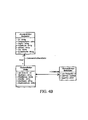
- FIG. 4A is a simplified block diagram of one embodiment of the present invention.
- FIG. 4A illustrates a model services system 250 that takes, as inputs, a specification of focal points 252, an object description 254 and a set of persistent data store mappings 256.
- System 250 then produces a dimensional model 258 based on the inputs.
- one aspect of the present invention pertains to data schema that enables a standardized description of inputs 252, 254 and/or 256.
- Model service system 250 is illustratively configured to generate dimensional model 258 based on information compiled within the organized schema format.
- FIG. 4A also illustrates an entity generator 260 that generates a set of object (or entities), referred to herein as business intelligence entities (or BI entities) 262, based on the dimensional model 258.
- entity generator 260 that generates a set of object (or entities), referred to herein as business intelligence entities (or BI entities) 262, based on the dimensional model 258.
- Focal points 252 represent certain data in the object model that is marked by the user as being a focal point of analysis.
- Focal points 252 can illustratively be specified in an XML specification file.
- An XML specification file is shown in Appendix A hereto.
- Object description 254 is an input which describes the object orientation relationships in a set of metadata corresponding to a set of objects.
- This can take the form of, for example, a UML class diagram.
- UML class diagram for a plurality of business entities (Customer, Order and OrderLine) is illustrated in FIG. 4B.
- Persistent data store mappings 256 map the data referred to by the object model to the persistent data store, in one illustrative embodiment the relational database 201 shown in FIG. 2. These are illustratively created by the user in the form of a map file, an example of which is found in Appendix B.
- the map file shown in Appendix B maps from a Customer entity to relational database tables.
- Model services system 250 receives inputs 252, 254 and 256 and automatically generates a dimensional model 258 based on those inputs.
- dimensional model 258 is inferred from the inputs supplied by the user, and there is no requirement for a second set of developers to be involved in recreating the business logic to obtain model 258.
- model services system 250 uses the associations and compositions in the object model specified by the object model description 254 to infer foreign key relationships in dimensional model 258.
- System 250 also uses the focal points of analysis defined by the user in file 252 and the persistent data store mappings 256 to create dimensional model 258 and access data through model 258.
- one aspect of the invention is simply the automatic generation of dimensional model 258.
- data provided to system 250 is organized in accordance with a standardized data schema, such as a standardized tagged format data schemata (e.g., an XML data schema).
- a standardized data schema such as a standardized tagged format data schemata (e.g., an XML data schema).
- entity generator 260 is provided. Entity generator 260 creates business intelligence entities 262 in the form of objects, from the cubes and dimensions in dimensional model 258. This is also described in greater detail below.
- FIG. 4C illustrates the system shown in FIG. 4A, in greater detail.
- the object model is represented by object description 254, and the mappings 256 are shown between the object model representation 254 and the relational database representation 264 which represents relational database 201.
- information is provided to model services 250 in accordance with a standardized data schema.
- FIG. 4C also shows dimensional model 258 in greater detail.
- Dimensional model 258 includes a Fact table 266 along with a plurality of dimensions 268 and 270 (the Customer dimension and the Order dimension). Each of the dimensions is formed of one or more tables. It is also worth noting that Fact table 266 includes the OrderlineID and CustomerID as foreign key references.
- FIG. 4C also illustrates one embodiment of a set of BI entities 262.
- the BI entities 262 include a BIOrderFact entity 270, a BIOrder entity 272 and a BICustomer entity 274. Entities 272 and 274 are related to entity 270.
- the dimensional model will require a snowflake-schema, such as that shown in dimensional model representation 258. It can thus be inferred that two dimensions will be created. Order and Customer.
- the Order dimension will have two levels, Order and OrderLine.
- the measures (or numeric values) in the Fact table 266 will include UnitPrice and Quantity and will come from the OrderLine entities.
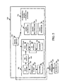
- FIG. 5 is a more detailed block diagram of model services system 250.
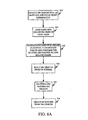
- FIG. 6A is a flow diagram better illustrating the operation of system 250 shown in FIG. 5.
- FIGS. 5 and 6A will be described in conjunction with one another.
- FIG. 5 shows that model services system 250 includes a model service component 300, a map system 302 and a dimensional model construction system 304.
- Map system 302 includes entity relation (ER) mapper 306, map loader 308, and map walker 310.
- Dimensional model construction system 304 includes model generator 312, model materializer 314 and model processor 316.
- FIG. 5 also illustrates entity generator 260 and BI entities 262.
- Model services component 300 provides a main user interface to accept focal point specification 252, object description 254 and ER mappings 256.
- information e.g., information items 252, 254 and 256
- the schema is illustratively configured to facilitate an automated process of constructing a dimensional model.
- Model services component 300 can also invoke the functionality associated with map system 302, dimensional model construction system 304 and entity generator 260.
- model services system 250 receives, through the top level interface implemented by component 300, focal point specification 252, object description 254 and persistent data storage mappings 256. This is indicated by block 320 in FIG. 6A.
- model services system 250 receives, as the object description, the UML class diagram shown in FIG. 6B. It is similar to that shown in FIG. 4B, except that it is slightly more complex and includes a bit more detail.
- Model services component 300 provides these inputs to map system 302 and invokes certain functionality in map system 302.
- the user uses the ER mapper, the user produces serialized ER maps 256 to described how the object model is mapped to the relational database.
- These serialized maps 322 are then loaded by map loader 308.
- Map loader 308 deserializes those maps and converts them to entity map (EM) objects 324.
- EM objects 324 The precise form of EM objects 324 is not important. They are simply objects generated from the serialized maps 322 that are predefined such that the structure of EM objects 324 is known by map walker 310. Loading maps 322 and creating EM objects 324 is indicated by block 323 in FIG. 6A.
- Map walker 310 navigates EM objects 324 and generates a data set schema to represent tables and columns that the entities are mapped to in the relational database, and to represent the relationship among them. Navigating the EM objects to create data set schema 326 is indicated by block 325 in FIG. 6A.
- the data set schema 326 generated by map walker 340 forms the basis for constructing a dimensional model cube in the dimensional model.
- Map walker 310 can also fill in any additional information in the data set schema 326 required by the dimensional model.
- map walker 310 generates queries 328 to tables in the relational database that will be used to define Fact tables in the dimensional models.
- Schema 326 is then provided to dimensional model construction system 304.
- model generator 312 builds dimensional model cubes based on schema 326. Building the dimensional model cubes from data set schema 326 is illustrated by block 330 in FIG. 6A and is described in greater detail below with respect to FIG. 7.
- Model materializer 314 provides an interface to materialize the dimensional models generated by model generator 312. Materializing the dimensional models is indicated by block 332 in FIG. 6A.
- Model processor 316 provides an interface to process the models materialized by model materializer 314.It should be noted that, at this point, the dimensional model can be queried using MDX or any other language used to query a multi-dimensional model.
- entity generator 260 is invoked by system 250 to generate BI entities 262 from the dimensional model created. Creating BI entities from the dimensional model objects is illustrated by block 334 in FIG. 6A and is described in greater detail below with respect to FIGS. 10A-10B.
- FIG. 7 is a flow diagram better illustrating the creation of a dimensional model from an object model using the map walker 310 and dimensional model construction system 304 shown in FIG. 5. From the ER mappings associated with each entity in the object model described, the relational database tables involved with those entities are retrieved. This is indicated by block 400 in FIG. 7. For each table retrieved, a table object is created. The table object has fields which include all of the columns associated with the table. This is indicated by block 402 in FIG. 7.
- Foreign key relationships among the table and column objects created are projected based on the associations and compositions among objects described in the object model description (such as the UML class diagram) being processed.
- the map walker 310 then traverses foreign key relationships from each table object created, for a corresponding entity that has been marked as a focal point for analysis. Recall that the focal points are specified by a focal point specification file which has also been input by the user.
- the foreign key relationships are traversed in a many-to-one direction toward table objects whose corresponding entity has been marked as a focal point for analysis, in order to generate a named query.
- the named query can be synthesized by combining the identified tables using an appropriate persistent data store query statement (such as a structured query language (SQL) statement).
- SQL structured query language
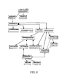
- FIG. 8 illustrates one exemplary class diagram for a generalized form of a multi-dimensional object in the dimensional model.
- FIG. 9 illustrates one exemplary dimensional model materialized and illustrating the foreign key relationships between the Fact table and the various dimensions associated with it.
- Appendix C illustrates another embodiment of pseudo code illustrating how model services system 250 calls the various components thereof in order to implement the functionalities discussed.
- the dimensional model an example of which is shown in FIG. 9, has been automatically generated by inferring foreign key relationships from the structure (compositions and associations) in the object model.
- the user can query the automatically generated dimensional model using tools designed for that purpose.
- MDX is a language designed to query a dimensional database.
- FIG. 10 shows a screen shot having a query field 430 which contains an MDX query expression.
- FIG. 10 also includes a result field 432 which contains the results returned by the query.
- BI entities 262 converts the automatically created dimensional model into another set of objects referred to herein as BI entities 262 so that they can be queried by users using object oriented expressions, rather than the complicated syntactical expressions required by dimensional model querying languages.
- BI entities 262 are created.
- BI entities 262 provide a conventional object oriented view of the underlying dimensional model 258. A user can thus create efficient query criteria and consume dimensional data in a manner in which the actual querying of the dimensional model is performed transparently to the user. BI entities 262 hide the dimensional model details, such as the cube, the dimensions, the hierarchy, the native query language, etc., and the user is only required to use objects and attributes.
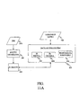
- FIG. 11A illustrates entity generator 258, along with data access system 500 which, itself, includes a BI service component 502, a BI criteria component 504 and a BI metadata discovery component 506.
- FIG. 11B is a flow diagram better illustrating how entity generator 258 generates BI entities 262.
- Entity generator 260 In order to generate BI entities 262, recall that entity generator 260 has access to underlying dimensional model 258. Entity generator 260 first retrieves a Fact table from dimensional model 258. This is indicated by block 510 in FIG. 11B. Entity generator 260 then generates a primary BI entity for the Fact table retrieved. The numerical values (or measures) in the Fact table become the properties of the newly created BI entity. Generating a primary BI entity for the retrieved Fact table is indicated by block 512 in FIG. 11B.
- Entity generator 260 then generates a non-primary BI entity for each dimension of the Fact table. It should be noted that nested classes can be used to maintain the original structure, hierarchy, and levels of the dimensional model. Generating the non-primary BI entities is indicated by block 514 in FIG. 11B. Entity generator 260 performs these operations for each Fact table in dimensional model 258, as indicated by block 516.
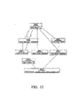
- FIG. 12 illustrates one exemplary interface implemented by the model service to generate code for accessing a created dimensional model.
- the interface allows the model service to convey information on the structure of the dimensional model to the code generator.
- a dimensional model consists of a cube with measures and a number of dimensions with hierarchies and attributes.
- FIG. 12 shows the relationships among these components of the dimensional model.
- the interface for invoking entity generator 260 is illustrated in FIG. 13.
- Appendix D illustrates the interfaces supported by the various components of system 250, and by entity generator 260.
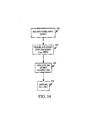
- FIG. 14 is a flow diagram better illustrating how data represented by BI entities 262 is accessed using data access system 500.
- a user input query 520 is provided to data access system 500.
- Receiving the user input query is indicated by block 522 in FIG. 14.
- BI criteria component 504 illustratively provides an interface through which the user can input user input query 520.
- the BI criteria interface is illustrated in FIG. 15 and an illustrative class diagram for BI criteria component 504 is illustrated by FIG. 16.
- the user input query 520 is converted by BI service component 502 into a dimensional model query expression, such as an MDX expression, which can be executed against the dimensional model 258.
- a dimensional model query expression such as an MDX expression
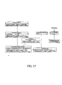
- FIG. 17 One exemplary class diagram for BI service component 502 is illustrated in FIG. 17. Translation of the user input query 520 into the dimensional model query and execution of the dimensional model query against the dimensional model are indicated by blocks 524 and 526 in FIG. 14.
- MDX is used as an example only, and any of a wide variety of different dimensional model query expressions can be supported by the BI criteria component 504.
- the following is one exemplary list of MDX expressions which are supported by BI service component 502 and BI criteria component 504, although it should be emphasized that other, different, or additional expressions can be supported as well:
- the following illustrates one exemplary criteria definition which forms the user input query 520 in the C-Sharp programming language.
- BI service component 502 After the dimensional model query is executed, BI service component 502 then returns a result set as indicated by block 528 in FIG. 14.
- BI metadata discovery component 506 can also be provided.
- BI metadata discovery component 506 is illustratively provided to perform a system wide BI entity search and to return detailed metadata retrieved for one or more BI entities. Of course, this can be useful to the user.
- Sales cube in dimensional model 258 has two measures, SalesUnits and SalesDollars, and one dimension "product" which in turn has only one hierarchy "cat", which in turn, has one level “category”.
- the generated BI class codes illustratively looks as follows:
- BI criteria component 504 One example of a user input query input through BI criteria component 504 is as follows:
- FIG. 18 An illustrative and exemplary result set returned based on the user input query is shown in FIG. 18.
- One aspect of the present invention automatically generates a dimensional model from an object model.
- the automatic generation is performed by inferring the dimensional model from relationships specified in the object model and user-designated focal points, as well as mappings back to the relational database.
- the information upon which the inference of the dimensional model is based is provided to the generator (e.g., the model service generator) in accordance with a an organized data schema, illustratively a tagged format data schema (e.g., an XML data schema.
- objects are provided to abstract away from the specifics of a dimensional model. Therefore, a user can access a dimensional model using only object oriented expressions, without requiring specific knowledge of any dimensional model querying language.
- both systems are used together such that the dimensional model is automatically created from a user-specified object model, and the entities which abstract away from the dimensional models are automatically created as well.
- the focal points, a description of the object model and its persistent data storage mappings all a user must do is provide the focal points, a description of the object model and its persistent data storage mappings, and this embodiment of the present invention automatically generates the necessary components for the user to access the data according to a desired reporting structure using only object oriented expressions without going through the laborious tasks of manually creating a dimensional model and then generating dimensional model-specific queries against the dimensional model.
- a model services system 250 takes, as inputs, a specification of focal points 252, an object description 254 and a set of persistent data store mappings 256.
- System 250 then produces a dimensional model 258 based on the inputs.
- a standardized model definition schema such as but not limited to a tagged format data schema, is provided to format the system 250 inputs so as to support the autonomous generation of the dimensional model.
- the standardized model definition schema is an XML schema that enables an object-relational model to be specified and decorated with extra metadata so as to support inference of a dimensional model therefrom.
- the schema supports description of any or all of the following data elements:
- a processing engine e.g., model services system 250
- a processing engine is illustratively configured to develop (e.g., autonomously generate) a dimensional model.
- the schema provides a predictable data format to the processing engine.
- the root XML tag is the ⁇ Entities> tag.
- This root tag similar to most of the tags in the schema, has an attribute called "name”.
- the name attribute of the ⁇ Entities> tag provides a name for the model being defined.
- ⁇ Entity> elements are defined.
- entity is illustratively equivalent to a class in the object orientation paradigm of programming.
- An entity has a name, a reference to its base (in an inheritance hierarchy) and its parent (in a composition hierarchy).
- An ⁇ Entity> element contains five potential child elements (Table, Fields, Associations, Compositions and Hierarchies).
- the ⁇ Table> element specifies primary database table fields that the containing ⁇ Entity> are mapped to. It can illustratively be either a physical database table or a logical table defined by the result of a SQL statement.
- the ⁇ Fields> element is utilized to declare multiple ⁇ Field> elements that the entity is consisted of.
- Each ⁇ Field> element illustratively contains information on how the field is mapped to a database table column.
- the ⁇ Associations> element and ⁇ Compositions> element declare multiple ⁇ Association> elements and ⁇ Composition> elements, respectively.
- Each ⁇ Association> element illustratively declares how a set of fields of its entity is related to a set of fields in another entity in a many-to-one relationship.
- Each ⁇ Composition> element serves a similar purpose but for one-to-many relationships.
- a ⁇ Hierarchy> element under ⁇ Hierarchies> declares a semantic hierarchical relationship among a subset of fields organized in levels (for example, Country, State, County and Zip Code).
- the ⁇ Entities> element is the root element of the schema (e.g., the root element of an XML document). It represents the model being defined.
- the name uniquely identifies the model. It is used as the basis for the name of the cube generated in the dimensional model.
- namespace This is an optional namespace that is used for code generated to facilitate data access from the inferred dimensional model.
- Entity An ⁇ Entities> element consists of multiple ⁇ Entity> elements, each of which specifies an entity defined for the model.
- the ⁇ Entity> element specifies an entity of the model. It represents the concept of a class in the object-orientated programming paradigm.
- name The name uniquely identifies the entity in the set of entities in the model. It is used as the basis for the name of the dimension created for the entity in the dimensional model.
- This tag provides the name of the base entity for this entity within an inheritance hierarchy.
- This tag provides the name of the parent entity of this entity within a composition hierarchy.
- the parent entity will have a composition relationship to this entity.
- Table This is the primary database table from which the fields of the entity declared under the ⁇ Fields> element will retrieve values. Refer to the section on the ⁇ Table> element for rules governing the use of the element.
- Associations This is an optional list of ⁇ Association> elements defined for the entity.
- the entity may also inherit additional associations from its base entity. Refer to the section on the ⁇ Association> element for more details.
- compositions This is an optional list of ⁇ Composition> elements defined for the entity.
- the entity may also inherit additional compositions from its base entity. Refer to the section on the ⁇ Composition> element for more details.
- Hierarchies This is an optional list of ⁇ Hierarchy> elements defined for the entity.
- a hierarchy is defined in terms of fields from the entity. Refer to the section on the ⁇ Hierarchy> element for more details.
- the table can either be a real database table or a virtual table consisting of data returning from the given SQL query:
- an entity can inherit additional fields from its base entity which are not declared under this entity's ⁇ Fields> element but under the base entity's ⁇ Fields> element. In that case, those fields will retrieve values from the base entity's ⁇ Table> element if the table name is not an empty string. Otherwise, those fields will retrieve values from this entity's ⁇ Table> element.
- the definition under this entity will illustratively override the definition under the base entity. Also, this makes the field an implicit link between the tables defined under the two entities. A database join operation on the two tables using the link is used to retrieve values for the full set of fields in the derived entity, including those which are inherited from its base.
- name This is the name of the logical database table from which fields of the entity declared under the ⁇ Fields> element are retrieving values. If the entity is abstract, which means that its fields are only mapped by its derived entities, the name of the table can be an empty string.
- sql This is the SQL query which defines the data for the entity, if a physical database table is not named.
- the set of data types allowed is dependent at least on the software platform for which the model is designed.
- One exemplary platform to which the present invention is not limited, is the Microsoft .NET platform offered by Microsoft Corporation of Redmond, Washington.
- this column This is the name of the column in the table to which the field is mapped. If the same field is also declared in the base entity, this column mapping illustratively takes precedence over the column mapping in the base entity. However, the two columns also provide a link for the two tables under the two entities. The link is used to construct a join query to obtain a full set of field values for the derived entity (including those inherited from the base entity). If the table element for this entity has an empty string as its name, the column attribute illustratively provides a default column name for the mapping of this field in all of its derived entities. As explained, the mapping can be overridden.
- sqltype This specifies the SQL data type for the column. For example, char(20), int, money, etc.
- keycol This is an optional boolean value used to indicate whether the field is part of the primary key of the entity. Key columns so declared become the key columns of the dimension constructed in the dimensional model. The keycol property is inherited alongside the field by any derived entities.
- namecol This is an optional boolean value used to indicate whether the field is the name column of the entity.
- the name column is used in the axes of the result set of a query on the dimensional model. If no namecol is declared, one of the key columns will be used as the name column.
- the default value is "false”.
- the field so declared should be of a numeric type.
- timedim This is an optional boolean value used to indicate whether the field will be used to construct a time dimension for measures declared in the same entity. The default value is "false”. The field so declared should be of a datetime type.
- An association links the containing entity with another entity in a many-to-one relationship.
- the association is defined in terms of a collection of FieldRefPair, each of which links a field in the containing entity with a field in the other entity.
- name This is a name which uniquely identifies an association.
- Hierarchical This is an optional boolean value used to indicate whether this entity is related to the other entity in a hierarchical way semantically. Default value is "false”. For example, the "County” entity is so related to the "State” entity. This forms the basis of constructing hierarchies in the dimensional model.
- FieldRefPairs This is a collection of FieldRefPair each of which relates a field of this entity with a field of the related entity. See the section under FieldRefPair for more details.
- One of the fields belongs to the entity hosting the definition while the other belongs to the other entity defined under the relationship.
- the references can actually be fields defined under the base entities of the entities involved.
- Thisfield This is a name reference to the field in this entity (or any of its base entities).
- a composition links the entity with another entity in a one-to-many relationship.
- the composition is defined in terms of a collection of FieldRefPair, each of which links a field in the containing entity with a field in the other entity.
- name This is a name which uniquely identifies an composition.
- a hierarchy defines a semantically hierarchical relationship among a subset of fields defined in this entity.
- name This is a name which uniquely identifies a hierarchy within the context of an entity. It will be used as a basis for naming the hierarchy constructed under the dimension built for the entity.
- Levels This is a list of ⁇ Level> elements, each of which references a field in the containing entity. See the section for the ⁇ Level >element for more details.
- a lower level number field has a lower granularity.
- the State field has a lower level number as the County field.
- fieldref This is the name reference to a field of the containing entity which defines the level.
- the example model is made up several distinct entities, namely, SalesDoc, Customer, Order, OrderLine, Product, Supplier and Category.
- the model includes a basic inheritance scenario, use of hierarchies and hierarchical association, as well as the declaration of a time dimension.
- the SalesDoc entity is an abstract base entity for the Order entity, which has a composition relationship with OrderLine and an association relationship with Customer.
- the Category entity has a hierarchical association relationship with the Product entity.
- the field of Order. OrderDate has been tag with the "timedim" attribute so that it will be used as a time dimension.
- a collection of fields in the Customer and Supplier entities are declared to be part of hierarchies. Both the Freight field under the Order entity and the OrderQuantity field under the OrderLine entity have been marked as a measure.
- FIG. 19 illustrates a UML diagram representing the described example object-relational data model.
- example object-relational data model is characterized and formatted as follows:
- This data organized within the described tagged format data schema enables its underlying object-relational data model to be specified and decorated with metadata so that a dimensional model can be inferred therefrom.
- a processing engine configured to support the data schema autonomously generates a corresponding dimensional model.
- FIG. 20 illustrates a dimensional model that corresponds to the example object-relational data model, and was illustratively inferred based on the data organized within the described standardized data representation.
- a model services engine processes information in the form of a model definition schema in order to generate a corresponding dimensional model. It should be emphasized that, in accordance with one aspect of the present invention, the described model definition schema embodiments are beneficial at least in that they extensible enough to enable the model service engine to support different source models and target models.
- FIG. 21 is a block diagram illustrating an architecture that demonstrates the extensible characteristics of providing the data input in a format consistent with an embodiment of the described model definition schema.
- MDS model definition schema
- the extensibility of the MDS system is exemplified in FIG. 21 by the generation of models 1, 2 and N based on source models 1, 2 and M, respectively.
- This generalization implies that the complexity of model transformation can be reduced from N (sources) x M(targets) to N + M.
- any party e.g., a third party vendor
Landscapes
- Engineering & Computer Science (AREA)
- Databases & Information Systems (AREA)
- Theoretical Computer Science (AREA)
- Data Mining & Analysis (AREA)
- Physics & Mathematics (AREA)
- General Engineering & Computer Science (AREA)
- General Physics & Mathematics (AREA)
- Information Retrieval, Db Structures And Fs Structures Therefor (AREA)
Applications Claiming Priority (4)
| Application Number | Priority Date | Filing Date | Title |
|---|---|---|---|
| US10/386,633 US7275024B2 (en) | 2003-03-12 | 2003-03-12 | Automatic generation of a dimensional model for business analytics from an object model for online transaction processing |
| US386633 | 2003-03-12 | ||
| US727176 | 2003-12-03 | ||
| US10/727,176 US7313561B2 (en) | 2003-03-12 | 2003-12-03 | Model definition schema |
Publications (2)
| Publication Number | Publication Date |
|---|---|
| EP1473640A2 true EP1473640A2 (de) | 2004-11-03 |
| EP1473640A3 EP1473640A3 (de) | 2004-11-10 |
Family
ID=32993820
Family Applications (1)
| Application Number | Title | Priority Date | Filing Date |
|---|---|---|---|
| EP04005846A Withdrawn EP1473640A3 (de) | 2003-03-12 | 2004-03-11 | Automatische Generierung eines dimensionalen Modells für Online Analytische Datenverarbeitung (OLAP) aus einem Objektmodell für Online-Transaktionsverarbeitung (OLTP) |
Country Status (3)
| Country | Link |
|---|---|
| US (1) | US7313561B2 (de) |
| EP (1) | EP1473640A3 (de) |
| JP (1) | JP2004280823A (de) |
Cited By (2)
| Publication number | Priority date | Publication date | Assignee | Title |
|---|---|---|---|---|
| US20130254224A1 (en) * | 2012-03-26 | 2013-09-26 | Sap Ag | Dynamic relevant reporting |
| US12361031B1 (en) | 2024-04-23 | 2025-07-15 | Tesser Insights Inc | Machine learning based data structuring system and method for automating a dimensional data modelling process in data repositories |
Families Citing this family (116)
| Publication number | Priority date | Publication date | Assignee | Title |
|---|---|---|---|---|
| US7447687B2 (en) * | 2002-05-10 | 2008-11-04 | International Business Machines Corporation | Methods to browse database query information |
| US7680818B1 (en) * | 2002-12-18 | 2010-03-16 | Oracle International Corporation | Analyzing the dependencies between objects in a system |
| US7716167B2 (en) | 2002-12-18 | 2010-05-11 | International Business Machines Corporation | System and method for automatically building an OLAP model in a relational database |
| US7546226B1 (en) * | 2003-03-12 | 2009-06-09 | Microsoft Corporation | Architecture for automating analytical view of business applications |
| US7895191B2 (en) | 2003-04-09 | 2011-02-22 | International Business Machines Corporation | Improving performance of database queries |
| US7530015B2 (en) * | 2003-06-25 | 2009-05-05 | Microsoft Corporation | XSD inference |
| US20050108024A1 (en) * | 2003-11-13 | 2005-05-19 | Fawcett John Jr. | Systems and methods for retrieving data |
| JP2005321849A (ja) * | 2004-05-06 | 2005-11-17 | Fujitsu Ltd | データ分析支援プログラム、データ分析支援方法、およびデータ分析支援装置 |
| US7707143B2 (en) * | 2004-06-14 | 2010-04-27 | International Business Machines Corporation | Systems, methods, and computer program products that automatically discover metadata objects and generate multidimensional models |
| US20050283494A1 (en) * | 2004-06-22 | 2005-12-22 | International Business Machines Corporation | Visualizing and manipulating multidimensional OLAP models graphically |
| US7480663B2 (en) * | 2004-06-22 | 2009-01-20 | International Business Machines Corporation | Model based optimization with focus regions |
| US20060064429A1 (en) * | 2004-09-18 | 2006-03-23 | Chi Yao | Method and apparatus for providing assets reports categorized by attribute |
| US20060116922A1 (en) * | 2004-11-29 | 2006-06-01 | Microsoft Corporation | Efficient and flexible business modeling based upon structured business capabilities |
| US20060116919A1 (en) * | 2004-11-29 | 2006-06-01 | Microsoft Corporation | Efficient and flexible business modeling based upon structured business capabilities |
| US20060179067A1 (en) * | 2005-02-04 | 2006-08-10 | Bechtel Michael E | Knowledge discovery tool navigation |
| US20060229926A1 (en) * | 2005-03-31 | 2006-10-12 | Microsoft Corporation | Comparing and contrasting models of business |
| US20060229922A1 (en) * | 2005-03-31 | 2006-10-12 | Microsoft Corporation | Association and visualization of schematized business networks |
| US7606829B2 (en) * | 2005-04-14 | 2009-10-20 | International Business Machines Corporation | Model entity operations in query results |
| US20060241956A1 (en) * | 2005-04-22 | 2006-10-26 | Microsoft Corporation | Transforming business models |
| US8522194B2 (en) | 2005-12-30 | 2013-08-27 | Sap Ag | Software modeling |
| US8448137B2 (en) | 2005-12-30 | 2013-05-21 | Sap Ag | Software model integration scenarios |
| US8380553B2 (en) | 2005-12-30 | 2013-02-19 | Sap Ag | Architectural design for plan-driven procurement application software |
| US8402426B2 (en) | 2005-12-30 | 2013-03-19 | Sap Ag | Architectural design for make to stock application software |
| US8676617B2 (en) | 2005-12-30 | 2014-03-18 | Sap Ag | Architectural design for self-service procurement application software |
| US8316344B2 (en) | 2005-12-30 | 2012-11-20 | Sap Ag | Software model deployment units |
| US8370794B2 (en) | 2005-12-30 | 2013-02-05 | Sap Ag | Software model process component |
| US8396731B2 (en) | 2005-12-30 | 2013-03-12 | Sap Ag | Architectural design for service procurement application software |
| US8327319B2 (en) | 2005-12-30 | 2012-12-04 | Sap Ag | Software model process interaction |
| US8321831B2 (en) | 2005-12-30 | 2012-11-27 | Sap Ag | Architectural design for internal projects application software |
| US8326703B2 (en) | 2005-12-30 | 2012-12-04 | Sap Ag | Architectural design for product catalog management application software |
| US20070203718A1 (en) * | 2006-02-24 | 2007-08-30 | Microsoft Corporation | Computing system for modeling of regulatory practices |
| US7720803B2 (en) * | 2006-03-28 | 2010-05-18 | Sap Ag | Mapping of a transactional data model to a reporting data model |
| US8438119B2 (en) * | 2006-03-30 | 2013-05-07 | Sap Ag | Foundation layer for services based enterprise software architecture |
| US8396749B2 (en) | 2006-03-30 | 2013-03-12 | Sap Ag | Providing customer relationship management application as enterprise services |
| US8396761B2 (en) | 2006-03-30 | 2013-03-12 | Sap Ag | Providing product catalog software application as enterprise services |
| US8261181B2 (en) | 2006-03-30 | 2012-09-04 | Microsoft Corporation | Multidimensional metrics-based annotation |
| US8538864B2 (en) | 2006-03-30 | 2013-09-17 | Sap Ag | Providing payment software application as enterprise services |
| US8326702B2 (en) | 2006-03-30 | 2012-12-04 | Sap Ag | Providing supplier relationship management software application as enterprise services |
| US8442850B2 (en) | 2006-03-30 | 2013-05-14 | Sap Ag | Providing accounting software application as enterprise services |
| US8321832B2 (en) | 2006-03-31 | 2012-11-27 | Sap Ag | Composite application modeling |
| US8312416B2 (en) | 2006-04-13 | 2012-11-13 | Sap Ag | Software model business process variant types |
| US8190992B2 (en) * | 2006-04-21 | 2012-05-29 | Microsoft Corporation | Grouping and display of logically defined reports |
| US8126750B2 (en) | 2006-04-27 | 2012-02-28 | Microsoft Corporation | Consolidating data source queries for multidimensional scorecards |
| US7676589B2 (en) * | 2006-06-05 | 2010-03-09 | International Business Machines Corporation | Automatic generation of portlets for visualizing data by exploiting object relationships |
| US20080071799A1 (en) * | 2006-08-31 | 2008-03-20 | Business Objects, S.A. | Apparatus and method for an extended semantic layer specifying data model objects with calculated values |
| US8375041B2 (en) * | 2006-08-31 | 2013-02-12 | Business Objects Software Ltd | Processing queries against combinations of data sources |
| US9058307B2 (en) | 2007-01-26 | 2015-06-16 | Microsoft Technology Licensing, Llc | Presentation generation using scorecard elements |
| WO2008093723A1 (ja) * | 2007-01-30 | 2008-08-07 | Arkray, Inc. | HbA1c測定方法 |
| US8321805B2 (en) | 2007-01-30 | 2012-11-27 | Microsoft Corporation | Service architecture based metric views |
| US8495663B2 (en) | 2007-02-02 | 2013-07-23 | Microsoft Corporation | Real time collaboration using embedded data visualizations |
| US8095570B2 (en) | 2007-11-26 | 2012-01-10 | International Business Machines Corporation | Decorated model architecture for efficient model-driven application development |
| US8671121B2 (en) * | 2007-11-26 | 2014-03-11 | International Business Machines Corporation | Model augmentation in a model-driven application development environment |
| US7937410B2 (en) * | 2007-12-19 | 2011-05-03 | Sap Ag | Generic archiving of enterprise service oriented architecture data |
| US20090164413A1 (en) * | 2007-12-21 | 2009-06-25 | Sap Ag | Generic table structure to xml structure mapping |
| US8510143B2 (en) | 2007-12-31 | 2013-08-13 | Sap Ag | Architectural design for ad-hoc goods movement software |
| US8447657B2 (en) | 2007-12-31 | 2013-05-21 | Sap Ag | Architectural design for service procurement application software |
| US9405513B2 (en) * | 2008-04-18 | 2016-08-02 | Software Ag | Systems and methods for graphically developing rules for transforming models between description notations |
| US20090299955A1 (en) * | 2008-05-29 | 2009-12-03 | Microsoft Corporation | Model Based Data Warehousing and Analytics |
| US8271319B2 (en) * | 2008-08-06 | 2012-09-18 | Microsoft Corporation | Structured implementation of business adaptability changes |
| US20100057508A1 (en) * | 2008-09-02 | 2010-03-04 | Microsoft Corporation | Structured implementation of business functionality changes |
| US8195504B2 (en) * | 2008-09-08 | 2012-06-05 | Microsoft Corporation | Linking service level expectations to performing entities |
| US8321250B2 (en) | 2008-09-18 | 2012-11-27 | Sap Ag | Architectural design for sell from stock application software |
| US8818884B2 (en) | 2008-09-18 | 2014-08-26 | Sap Ag | Architectural design for customer returns handling application software |
| US8595077B2 (en) | 2008-09-18 | 2013-11-26 | Sap Ag | Architectural design for service request and order management application software |
| US8380549B2 (en) | 2008-09-18 | 2013-02-19 | Sap Ag | Architectural design for embedded support application software |
| US8401928B2 (en) | 2008-09-18 | 2013-03-19 | Sap Ag | Providing supplier relationship management software application as enterprise services |
| US8352338B2 (en) | 2008-09-18 | 2013-01-08 | Sap Ag | Architectural design for time recording application software |
| US8386325B2 (en) | 2008-09-18 | 2013-02-26 | Sap Ag | Architectural design for plan-driven procurement application software |
| US8315926B2 (en) | 2008-09-18 | 2012-11-20 | Sap Ag | Architectural design for tax declaration application software |
| US8359218B2 (en) | 2008-09-18 | 2013-01-22 | Sap Ag | Computer readable medium for implementing supply chain control using service-oriented methodology |
| US8374896B2 (en) | 2008-09-18 | 2013-02-12 | Sap Ag | Architectural design for opportunity management application software |
| US8150726B2 (en) | 2008-09-30 | 2012-04-03 | Microsoft Corporation | Linking organizational strategies to performing capabilities |
| US20100082380A1 (en) * | 2008-09-30 | 2010-04-01 | Microsoft Corporation | Modeling and measuring value added networks |
| US20100088685A1 (en) * | 2008-10-06 | 2010-04-08 | Microsoft Corporation | System and method for mapping a domain modeling language to a relational store |
| US7970728B2 (en) | 2008-10-23 | 2011-06-28 | International Business Machines Corporation | Dynamically building and populating data marts with data stored in repositories |
| US8655711B2 (en) * | 2008-11-25 | 2014-02-18 | Microsoft Corporation | Linking enterprise resource planning data to business capabilities |
| US8401908B2 (en) | 2008-12-03 | 2013-03-19 | Sap Ag | Architectural design for make-to-specification application software |
| US8311904B2 (en) | 2008-12-03 | 2012-11-13 | Sap Ag | Architectural design for intra-company stock transfer application software |
| US8738476B2 (en) | 2008-12-03 | 2014-05-27 | Sap Ag | Architectural design for selling standardized services application software |
| US8321306B2 (en) | 2008-12-03 | 2012-11-27 | Sap Ag | Architectural design for selling project-based services application software |
| US8671035B2 (en) | 2008-12-11 | 2014-03-11 | Sap Ag | Providing payroll software application as enterprise services |
| US20100153432A1 (en) * | 2008-12-11 | 2010-06-17 | Sap Ag | Object based modeling for software application query generation |
| US8280924B2 (en) * | 2009-03-26 | 2012-10-02 | Microsoft Corporation | Object-relational mapping with dynamic relational schemas |
| US8260825B2 (en) * | 2009-05-11 | 2012-09-04 | Business Objects Software Limited | Functionally-dependent analysis objects |
| US8504513B2 (en) | 2009-11-25 | 2013-08-06 | Microsoft Corporation | Auto-generation of code for performing a transform in an extract, transform, and load process |
| US9990416B2 (en) * | 2009-12-02 | 2018-06-05 | Business Objects Software Limited | Analysis groups for semantic layer |
| US9811353B1 (en) | 2010-07-29 | 2017-11-07 | Crimson Corporation | Remotely invoking dynamic classes on a computing device |
| US8516011B2 (en) * | 2010-10-28 | 2013-08-20 | Microsoft Corporation | Generating data models |
| US20120110004A1 (en) * | 2010-11-03 | 2012-05-03 | Microsoft Corporation | Homomorphism lemma for efficiently querying databases |
| US8682936B2 (en) * | 2010-12-15 | 2014-03-25 | Microsoft Corporation | Inherited entity storage model |
| US9665601B1 (en) * | 2010-12-16 | 2017-05-30 | Crimson Corporation | Using a member attribute to perform a database operation on a computing device |
| US8700632B2 (en) * | 2011-05-26 | 2014-04-15 | Ixia | Managing heterogeneous data |
| US9886474B2 (en) * | 2011-11-22 | 2018-02-06 | Microsoft Technology Licensing, Llc | Multidimensional grouping operators |
| US8510261B1 (en) * | 2012-05-29 | 2013-08-13 | Sap Ag | System and method of generating in-memory models from data warehouse models |
| US9672228B2 (en) | 2013-03-11 | 2017-06-06 | Honeywell International Inc. | Methods and systems for creating a complex user interface adapting a generic database software application to individually manage subset domains in complex database |
| US9471662B2 (en) | 2013-06-24 | 2016-10-18 | Sap Se | Homogeneity evaluation of datasets |
| US9569469B2 (en) * | 2013-07-26 | 2017-02-14 | Honeywell International Inc. | Methods and systems for providing intuitive direction for populating complex model content into a database |
| US8886671B1 (en) | 2013-08-14 | 2014-11-11 | Advent Software, Inc. | Multi-tenant in-memory database (MUTED) system and method |
| US10977224B2 (en) * | 2014-07-31 | 2021-04-13 | Quickbase, Inc. | Dynamic modeling of data in relational databases |
| US11288290B2 (en) * | 2014-12-18 | 2022-03-29 | Ab Initio Technology Llc | Building reports |
| US10855645B2 (en) | 2015-01-09 | 2020-12-01 | Microsoft Technology Licensing, Llc | EPC node selection using custom service types |
| WO2017100578A1 (en) * | 2015-12-10 | 2017-06-15 | Affirmed Networks, Inc. | Data driven automated provisioning of telecommunication applications |
| US10713314B2 (en) | 2016-01-29 | 2020-07-14 | Splunk Inc. | Facilitating data model acceleration in association with an external data system |
| US11038841B2 (en) | 2017-05-05 | 2021-06-15 | Microsoft Technology Licensing, Llc | Methods of and systems of service capabilities exposure function (SCEF) based internet-of-things (IOT) communications |
| KR102530337B1 (ko) | 2017-05-31 | 2023-05-08 | 마이크로소프트 테크놀로지 라이센싱, 엘엘씨 | Ipsec 지오그래픽 리던던시에 대한 분리 제어 및 데이터 평면 동기화 |
| US10856134B2 (en) | 2017-09-19 | 2020-12-01 | Microsoft Technolgy Licensing, LLC | SMS messaging using a service capability exposure function |
| EP3756384A1 (de) | 2018-02-20 | 2020-12-30 | Microsoft Technology Licensing, LLC | Dynamische auswahl von netzwerkelementen |
| IL277298B2 (en) | 2018-03-20 | 2025-03-01 | Affirmed Networks Inc | Systems and methods for network slicing |
| CN113169988B (zh) | 2018-07-23 | 2024-11-12 | 微软技术许可有限责任公司 | 用于智能地管理移动网络中的会话的系统和方法 |
| US11456949B1 (en) | 2020-11-18 | 2022-09-27 | Quickbase, Inc. | Routing networks with asynchronous message backup and replay |
| US11689451B1 (en) | 2020-11-18 | 2023-06-27 | Quickbase, Inc. | Routing networks and methods using dynamic configuration of web services |
| US12248458B1 (en) | 2020-11-19 | 2025-03-11 | Quickbase Inc. | Offline structured data navigation on a mobile device |
| US11455296B1 (en) | 2020-11-19 | 2022-09-27 | Quickbase Inc. | Offline structured data entry and data access on a mobile device |
| CN115481101A (zh) * | 2021-05-31 | 2022-12-16 | 华为技术有限公司 | 数据传输方法、电子设备及计算机可读存储介质 |
| US12386850B1 (en) | 2023-08-08 | 2025-08-12 | Eygs Llp | Systems and methods to convert data according to a schema |
| US12099883B1 (en) | 2023-10-27 | 2024-09-24 | Eygs Llp | Systems and methods to generate machine-executable programs configured to present data in cloud environments |
Family Cites Families (40)
| Publication number | Priority date | Publication date | Assignee | Title |
|---|---|---|---|---|
| US60707A (en) * | 1867-01-01 | Impbovement in boots md shoes | ||
| WO1995003586A1 (en) | 1993-07-21 | 1995-02-02 | Persistence Software, Inc. | Method and apparatus for generation of code for mapping relational data to objects |
| US6112199A (en) * | 1995-10-18 | 2000-08-29 | Nelson; Paul M. | Data item values |
| US6283572B1 (en) | 1997-03-04 | 2001-09-04 | Hewlett-Packard Company | Dynamic multi-pass print mode corrections to compensate for malfunctioning inkjet nozzles |
| US6010205A (en) | 1997-03-12 | 2000-01-04 | Raster Graphics Inc. | Method and apparatus for improved printing |
| CA2298530A1 (en) | 1997-08-01 | 1999-02-25 | David Neese | Ink-jet printer, method and system compensating for nonfunctional print elements |
| EP1068577A1 (de) | 1997-09-26 | 2001-01-17 | Ontos, Inc. | Objektmodelaufnahme und laufzeitmaschine zur verwendung von relationaler datenbank mit objektorientierter software |
| US6360223B1 (en) | 1997-12-22 | 2002-03-19 | Sun Microsystems, Inc. | Rule-based approach to object-relational mapping strategies |
| US6016497A (en) * | 1997-12-24 | 2000-01-18 | Microsoft Corporation | Methods and system for storing and accessing embedded information in object-relational databases |
| US6212524B1 (en) * | 1998-05-06 | 2001-04-03 | E.Piphany, Inc. | Method and apparatus for creating and populating a datamart |
| US20020008723A1 (en) | 1998-07-21 | 2002-01-24 | Xin Wen | Printer and method of compensating for malperforming and inoperative ink nozzles in a print head |
| EP0983855A3 (de) | 1998-08-31 | 2000-08-02 | Hewlett-Packard Company | Ersatz von Punkten zur Kompensierung fehlender Tintenstrahldüsen |
| US6356901B1 (en) * | 1998-12-16 | 2002-03-12 | Microsoft Corporation | Method and apparatus for import, transform and export of data |
| US6354689B1 (en) | 1998-12-22 | 2002-03-12 | Eastman Kodak Company | Method of compensating for malperforming nozzles in a multitone inkjet printer |
| US7007029B1 (en) | 1999-01-15 | 2006-02-28 | Metaedge Corporation | System for visualizing information in a data warehousing environment |
| US6665644B1 (en) | 1999-08-10 | 2003-12-16 | International Business Machines Corporation | Conversational data mining |
| CA2281331A1 (en) | 1999-09-03 | 2001-03-03 | Cognos Incorporated | Database management system |
| US7185016B1 (en) | 2000-09-01 | 2007-02-27 | Cognos Incorporated | Methods and transformations for transforming metadata model |
| US6381600B1 (en) * | 1999-09-22 | 2002-04-30 | International Business Machines Corporation | Exporting and importing of data in object-relational databases |
| US6785673B1 (en) * | 2000-02-09 | 2004-08-31 | At&T Corp. | Method for converting relational data into XML |
| TW487639B (en) | 2000-02-15 | 2002-05-21 | Acer Comm & Multimedia Inc | Ink-jet printer having abnormal compensation function of nozzle |
| US6768986B2 (en) * | 2000-04-03 | 2004-07-27 | Business Objects, S.A. | Mapping of an RDBMS schema onto a multidimensional data model |
| US6807518B1 (en) | 2000-04-13 | 2004-10-19 | Ford Motor Company | Method for analyzing product information |
| US20020070953A1 (en) | 2000-05-04 | 2002-06-13 | Barg Timothy A. | Systems and methods for visualizing and analyzing conditioned data |
| AUPQ766300A0 (en) | 2000-05-22 | 2000-06-15 | Canon Kabushiki Kaisha | Defective nozzle compensation |
| US6862574B1 (en) | 2000-07-27 | 2005-03-01 | Ncr Corporation | Method for customer segmentation with applications to electronic commerce |
| US7111010B2 (en) | 2000-09-25 | 2006-09-19 | Hon Hai Precision Industry, Ltd. | Method and system for managing event attributes |
| US6917937B1 (en) * | 2000-11-01 | 2005-07-12 | Sas Institute Inc. | Server-side object filtering |
| US6964023B2 (en) | 2001-02-05 | 2005-11-08 | International Business Machines Corporation | System and method for multi-modal focus detection, referential ambiguity resolution and mood classification using multi-modal input |
| US20020161778A1 (en) * | 2001-02-24 | 2002-10-31 | Core Integration Partners, Inc. | Method and system of data warehousing and building business intelligence using a data storage model |
| US20020147848A1 (en) | 2001-04-05 | 2002-10-10 | Burgin Daniel Keele | System and method for enabling communication between browser frames |
| US6732095B1 (en) * | 2001-04-13 | 2004-05-04 | Siebel Systems, Inc. | Method and apparatus for mapping between XML and relational representations |
| US7031955B1 (en) * | 2001-04-27 | 2006-04-18 | I2 Technologies Us, Inc. | Optimization using a multi-dimensional data model |
| US6907433B2 (en) * | 2001-08-01 | 2005-06-14 | Oracle International Corp. | System and method for managing object to relational one-to-many mapping |
| US20030120593A1 (en) | 2001-08-15 | 2003-06-26 | Visa U.S.A. | Method and system for delivering multiple services electronically to customers via a centralized portal architecture |
| US7818219B2 (en) | 2001-12-27 | 2010-10-19 | American Hungarian Technologies Inc. | Electronic realty and transaction system and method therein |
| US6980980B1 (en) | 2002-01-16 | 2005-12-27 | Microsoft Corporation | Summary-detail cube architecture using horizontal partitioning of dimensions |
| US7634478B2 (en) | 2003-12-02 | 2009-12-15 | Microsoft Corporation | Metadata driven intelligent data navigation |
| US8122044B2 (en) | 2003-03-12 | 2012-02-21 | Microsoft Corporation | Generation of business intelligence entities from a dimensional model |
| US7895191B2 (en) * | 2003-04-09 | 2011-02-22 | International Business Machines Corporation | Improving performance of database queries |
-
2003
- 2003-12-03 US US10/727,176 patent/US7313561B2/en not_active Expired - Fee Related
-
2004
- 2004-03-11 EP EP04005846A patent/EP1473640A3/de not_active Withdrawn
- 2004-03-11 JP JP2004069829A patent/JP2004280823A/ja active Pending
Cited By (3)
| Publication number | Priority date | Publication date | Assignee | Title |
|---|---|---|---|---|
| US20130254224A1 (en) * | 2012-03-26 | 2013-09-26 | Sap Ag | Dynamic relevant reporting |
| US9244988B2 (en) * | 2012-03-26 | 2016-01-26 | Sap Se | Dynamic relevant reporting |
| US12361031B1 (en) | 2024-04-23 | 2025-07-15 | Tesser Insights Inc | Machine learning based data structuring system and method for automating a dimensional data modelling process in data repositories |
Also Published As
| Publication number | Publication date |
|---|---|
| JP2004280823A (ja) | 2004-10-07 |
| US7313561B2 (en) | 2007-12-25 |
| EP1473640A3 (de) | 2004-11-10 |
| US20040181538A1 (en) | 2004-09-16 |
Similar Documents
| Publication | Publication Date | Title |
|---|---|---|
| US7313561B2 (en) | Model definition schema | |
| US7275024B2 (en) | Automatic generation of a dimensional model for business analytics from an object model for online transaction processing | |
| US7546226B1 (en) | Architecture for automating analytical view of business applications | |
| EP1457878B1 (de) | Automatische erzeugung eines objektmodells aus einem dimensionalmodell | |
| US7734657B2 (en) | Containment hierarchy in a database system | |
| Park et al. | Information systems interoperability: What lies beneath? | |
| US7149733B2 (en) | Translation of object queries involving inheritence | |
| US7412436B2 (en) | System and interface for manipulating a database | |
| US6611838B1 (en) | Metadata exchange | |
| US7672960B2 (en) | Performing operations on a set of objects in a database system | |
| EP1383056A2 (de) | Abfrage eines objekt-relationalen Datenbanksystems | |
| Bretherton et al. | Metadata: A user's view | |
| US20040015511A1 (en) | Query services for database system | |
| US20040019586A1 (en) | Property and object validation in a database system | |
| US7613715B2 (en) | Map and data location provider | |
| CN116578614A (zh) | 一种管道设备的数据管理方法、系统、介质及设备 | |
| Zhang | Object‐oriented database systems in manufacturing: selection and applications | |
| US7769750B2 (en) | Metadata based hypermedia management system | |
| US7970867B2 (en) | Hypermedia management system | |
| Brandani | Multi-database Access from Amos II using ODBC | |
| Dittrich et al. | Object-oriented DBMS and beyond | |
| Nargesian | Bridging decision applications and multidimensional databases | |
| KWOK-WAI | ‘Using The Metadatabase Approach For Data Integration And OLAP | |
| Batory et al. | Introductory P2 System Manual | |
| DELDICQUE | IST Project IST-1999-11009 Commission of the European Communities |
Legal Events
| Date | Code | Title | Description |
|---|---|---|---|
| PUAI | Public reference made under article 153(3) epc to a published international application that has entered the european phase |
Free format text: ORIGINAL CODE: 0009012 |
|
| PUAL | Search report despatched |
Free format text: ORIGINAL CODE: 0009013 |
|
| AK | Designated contracting states |
Kind code of ref document: A2 Designated state(s): AT BE BG CH CY CZ DE DK EE ES FI FR GB GR HU IE IT LI LU MC NL PL PT RO SE SI SK TR |
|
| AX | Request for extension of the european patent |
Extension state: AL LT LV MK |
|
| AK | Designated contracting states |
Kind code of ref document: A3 Designated state(s): AT BE BG CH CY CZ DE DK EE ES FI FR GB GR HU IE IT LI LU MC NL PL PT RO SE SI SK TR |
|
| AX | Request for extension of the european patent |
Extension state: AL LT LV MK |
|
| 17P | Request for examination filed |
Effective date: 20050119 |
|
| AKX | Designation fees paid |
Designated state(s): AT BE BG CH CY CZ DE DK EE ES FI FR GB GR HU IE IT LI LU MC NL PL PT RO SE SI SK TR |
|
| 17Q | First examination report despatched |
Effective date: 20070426 |
|
| RIN1 | Information on inventor provided before grant (corrected) |
Inventor name: YEH, ADAM Inventor name: LO, ALVIN |
|
| STAA | Information on the status of an ep patent application or granted ep patent |
Free format text: STATUS: THE APPLICATION HAS BEEN WITHDRAWN |
|
| 18W | Application withdrawn |
Effective date: 20120925 |