EP1473675A2 - Conversion de résolution d'une image numérique par codage et décodage hiérarchique - Google Patents
Conversion de résolution d'une image numérique par codage et décodage hiérarchique Download PDFInfo
- Publication number
- EP1473675A2 EP1473675A2 EP03256675A EP03256675A EP1473675A2 EP 1473675 A2 EP1473675 A2 EP 1473675A2 EP 03256675 A EP03256675 A EP 03256675A EP 03256675 A EP03256675 A EP 03256675A EP 1473675 A2 EP1473675 A2 EP 1473675A2
- Authority
- EP
- European Patent Office
- Prior art keywords
- layer
- hierarchy
- image
- image data
- decoding
- Prior art date
- Legal status (The legal status is an assumption and is not a legal conclusion. Google has not performed a legal analysis and makes no representation as to the accuracy of the status listed.)
- Withdrawn
Links
Images













Classifications
-
- G—PHYSICS
- G06—COMPUTING OR CALCULATING; COUNTING
- G06T—IMAGE DATA PROCESSING OR GENERATION, IN GENERAL
- G06T9/00—Image coding
-
- H—ELECTRICITY
- H04—ELECTRIC COMMUNICATION TECHNIQUE
- H04N—PICTORIAL COMMUNICATION, e.g. TELEVISION
- H04N19/00—Methods or arrangements for coding, decoding, compressing or decompressing digital video signals
- H04N19/10—Methods or arrangements for coding, decoding, compressing or decompressing digital video signals using adaptive coding
- H04N19/134—Methods or arrangements for coding, decoding, compressing or decompressing digital video signals using adaptive coding characterised by the element, parameter or criterion affecting or controlling the adaptive coding
-
- H—ELECTRICITY
- H04—ELECTRIC COMMUNICATION TECHNIQUE
- H04N—PICTORIAL COMMUNICATION, e.g. TELEVISION
- H04N19/00—Methods or arrangements for coding, decoding, compressing or decompressing digital video signals
- H04N19/10—Methods or arrangements for coding, decoding, compressing or decompressing digital video signals using adaptive coding
- H04N19/102—Methods or arrangements for coding, decoding, compressing or decompressing digital video signals using adaptive coding characterised by the element, parameter or selection affected or controlled by the adaptive coding
- H04N19/132—Sampling, masking or truncation of coding units, e.g. adaptive resampling, frame skipping, frame interpolation or high-frequency transform coefficient masking
-
- H—ELECTRICITY
- H04—ELECTRIC COMMUNICATION TECHNIQUE
- H04N—PICTORIAL COMMUNICATION, e.g. TELEVISION
- H04N19/00—Methods or arrangements for coding, decoding, compressing or decompressing digital video signals
- H04N19/10—Methods or arrangements for coding, decoding, compressing or decompressing digital video signals using adaptive coding
- H04N19/169—Methods or arrangements for coding, decoding, compressing or decompressing digital video signals using adaptive coding characterised by the coding unit, i.e. the structural portion or semantic portion of the video signal being the object or the subject of the adaptive coding
- H04N19/187—Methods or arrangements for coding, decoding, compressing or decompressing digital video signals using adaptive coding characterised by the coding unit, i.e. the structural portion or semantic portion of the video signal being the object or the subject of the adaptive coding the unit being a scalable video layer
-
- H—ELECTRICITY
- H04—ELECTRIC COMMUNICATION TECHNIQUE
- H04N—PICTORIAL COMMUNICATION, e.g. TELEVISION
- H04N19/00—Methods or arrangements for coding, decoding, compressing or decompressing digital video signals
- H04N19/44—Decoders specially adapted therefor, e.g. video decoders which are asymmetric with respect to the encoder
-
- H—ELECTRICITY
- H04—ELECTRIC COMMUNICATION TECHNIQUE
- H04N—PICTORIAL COMMUNICATION, e.g. TELEVISION
- H04N19/00—Methods or arrangements for coding, decoding, compressing or decompressing digital video signals
- H04N19/50—Methods or arrangements for coding, decoding, compressing or decompressing digital video signals using predictive coding
- H04N19/59—Methods or arrangements for coding, decoding, compressing or decompressing digital video signals using predictive coding involving spatial sub-sampling or interpolation, e.g. alteration of picture size or resolution
-
- H—ELECTRICITY
- H04—ELECTRIC COMMUNICATION TECHNIQUE
- H04N—PICTORIAL COMMUNICATION, e.g. TELEVISION
- H04N19/00—Methods or arrangements for coding, decoding, compressing or decompressing digital video signals
- H04N19/60—Methods or arrangements for coding, decoding, compressing or decompressing digital video signals using transform coding
- H04N19/63—Methods or arrangements for coding, decoding, compressing or decompressing digital video signals using transform coding using sub-band based transform, e.g. wavelets
- H04N19/635—Methods or arrangements for coding, decoding, compressing or decompressing digital video signals using transform coding using sub-band based transform, e.g. wavelets characterised by filter definition or implementation details
Definitions
- the present invention relates to resolution conversion and, more particularly, to resolution conversion with relation to a hierarchical coding method.
- ISO which is an international standardized coding method for a still image and JPEG recommended by ITU-T, is widely used.
- JPEG is based on the discrete cosine transform and has a problem of block distortions generated at a high compression ratio.
- a subband coding method another conversion method, is used.
- a digital image signal is divided into bands by, e.g., a filter for wavelet transform (the band division is called "wavelet transform”, hereinafter), which is then compressed.
- the filtered signals are down-sampled at intervals corresponding to the passbands, and compressed using a tendency of energy of output signals from the filters (Martin Vetterli, "Wavelet transform and Subband Coding", Journal of the Institute of Electronics, Information and Communication Engineers, Vol.74, No.12, PP.1275-1278, December 1991).
- Subband coding is hierarchical coding, and encoded data can be decoded up to a desired layer of hierarchy without decoding all layers of hierarchy.
- Subband coding has a virtue of easily realizing efficient decoding, but also has a drawback of including alias which degrade image quality.
- Wavelet transform is generally said to be a lower concept or modification of subband coding. It should be noted that "wavelet” in this specification is not limited to a technique using wavelet transform filters, and should be understood to widely include a technique of using filters adapted in subband coding.
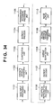
- Fig. 34 shows a basic configuration of an apparatus which performs band division by filters used in subband coding, e.g., wavelet transform filters, and synthesis.
- Orthogonal mirror filters are generally used as the wavelet transform f ilters .
- reference numeral 1101 denotes an image input processing unit which pre-processes image data; 1102, a discrete wavelet transform unit; 1103, a quantization unit; 1104, an entropy encoder; 1105, a transmission/recording processing unit; 1106, a reception/reproduction processing unit; 1107, an entropy decoder; 1108, an inverse quantization unit; 1109, an inverse discrete wavelet transform unit; and 1110, an image output unit.
- the configurations from the image input processing unit 1101 through the transmission/recording processing unit 1105 constitute an encoding apparatus, and data outputted from the encoding apparatus is transferred via communication or a recording medium to an decoding apparatus, constituted by the configurations from the reception/reproduction processing unit 1106 through the image output unit 1110, where an image is reproduced.
- Encoding processing is explained first.
- An input image signal undergoes processes, such as ⁇ conversion and color conversion, in the image input processing unit 1101, and enters the discrete wavelet transform unit 1102.
- the discrete wavelet transform unit 1102 performs discrete wavelet transform on the input image signal both in the vertical and horizontal directions.
- wavelet transform processing wavelet transform is recursively performed on a low frequency component obtained by wavelet transform, thereby generating multiple layers of hierarchy.
- the discrete-wavelet-transformed image data is inputted to the quantization unit 1103.
- the quantization unit 1103 can change the compression ratio and coding rate by quantizing the wavelet data with predetermined characteristics.
- the quantized image data is compressed by the entropy encoder 1104 utilizing the redundancy of the data.
- the transmission/recording processing unit 1105 performs processes for transferring the coded data, and for converting the coded data to a format suited for a medium when recording the data on the medium.
- the image is hierarchically encoded in the foregoing processing, and the output data is transferred or recorded on a storage medium.
- the decoding processing is realized by performing the processes of the encoding processing in the inverse order.
- the reception/reproduction processing unit 1106 separates and reproduces image data which is transferred or recorded on a medium, and the entropy decoder 1107 decodes the image data, the inverse quantization unit 1108 decodes the image data to data before quantization, then the inverse discrete wavelet transform unit 1109 decodes the data into the original image data. Thereafter, the original image data is converted to image data suitable for designation of output by the image output unit 1110, then outputted.
- the wavelet transform is generally octave transform, an image, corresponding to layer/layers of hierarchy, whose size is 1/2 n of the original size can be easily obtained.
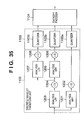
- Image data is inputted to a low pass filter 1203 for analysis (referred to as “analysis LPF”, hereinafter) for band division and to a high pass filter 1201 for analysis (referred to as “analysis HPF”, hereinafter) for band division, and separated into a low frequency band signal and a high frequency band signal. Since the band width of each separated signal is a half the band width of the original image data, the down samplers 1202 and 1204 sample the signals. The high frequency band signal is directly outputted to the quantization unit 1103.
- the low frequency band signal is recursively processed by an analysis HPF 1205, an analysis LPF 1207, and down samplers 1206 and 1208.
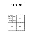
- Fig. 35 shows an example of outputting three layers of hierarchy by two cycles of processing for explanatory convenience. Its concept is shown in Fig. 38.
- data corresponding to HL1, LH1, HH1 shown in Fig. 38 is obtained by the analysis HPF 1201 and the down sampler 1202, and data corresponding to LL1 is obtained by the analysis LPF 1203 and the down sampler 1204.
- the LL1 is recursively processed, and data corresponding to HL2, LH2, HH2 in Fig. 38 is obtained by the analysis HPF 1205 and the down sampler 1206, and data corresponding to LL2 in Fig. 38 is obtained by the analysis LPF 1207 and the down sampler 1208.
- the respective frequency band data is quantized by the quantizer 1103a to 1103c corresponding to the respective frequency bands, and encoded by the entropy encoder 1104 for each band, then outputted by the transmission/recording processing unit 1105.
- Fig. 36 shows an example of another configuration of the discrete wavelet transform unit 1102.
- the same elements as those in Fig. 35 are referred to by the same reference numerals.
- the transmission/recording processing unit 1105 when data of all the layers of hierarchy of an image is not needed, the transmission/recording processing unit 1105 outputs information indicating it to a controller 1209.
- the controller 1209 controls so that data of a needless layer/layers of hierarchy is not encoded out of hierarchically corded data of each frequency band.
- the switch unit 1210 opens a switch or switches corresponding to the data of the higher layer/layers of hierarchy, thereby preventing the data of the layer/layers of hierarchy which is not encoded from being inputted to the entropy encoder 1104. At this time, it is possible to reduce a processing load and energy consumption by stopping the needless operations performed by a part of the discrete wavelet transform unit 1102 and the entropy encoder 1104.
- an inverse quantizer 108a corresponds to the quantizer 1103a for quantizing hierarchical data of HL1, LH1 and HH1
- an inverse quantizer 1108b corresponds to the quantizer 1103b for quantizing hierarchical data of HL2, LH2, and HH2
- an inverse quantizer 1108c corresponds to the quantizer 1103c for quantizing hierarchical data of LL2 in the low frequency band.
- the inversely quantized signals sequentially undergo inverse wavelet transform from the data of LL2 .
- LL2 is interpolated with 0's by an up sampler 1301, and further undergoes interpolation processing by a LPF 1302 for synthesis (referred to as "synthesis LPF”, hereinafter) for band synthesis.
- LPF LPF
- HL2, LH2, and HH2 are similarly up-sampled by the up sampler 1304, undergo interpolation processing by a HPF 1305 for synthesis (referred to as “synthesis HPF”, hereinafter) for band synthesis, then added to the LL2 component by an adder 1303, thereby LL1 is reproduced.
- the reproduced LL1 is further up-sampled by an up sampler 1306, and interpolated and reproduced by a synthesis LPF 1307.
- HL1, LH1, and HH1 are also up-sampled by an up sampler 1309, interpolated and reproduced by a synthesis HPF 1310, then added to the LL1 component by an adder 1308, thereby an original image is reproduced.
- an image having 1/2 n of the original size can be easily outputted.
- a range where a rip occurs becomes wide in the blocking frequency range of a filter when a filter having many taps, such as finite impulse response (FIR) filter is used for band division, and ringing is caused around portions where signal level changes greatly, e.g., at edges in an image.
- FIR finite impulse response
- the same filter is conventionally used for all the band division processes. This causes a relative increase in the number of taps of a filter due to down sampling operation as the band division progresses. As a result, ringing occurs in a wide area around an edge of an image.
- a filter having a smaller number of taps and having a broad passband characteristic is used to restrain the occurrence range ringing.
- the wavelet transform filter an orthogonal mirror filter is generally used.
- Fig. 39 shows characteristics of a 9 ⁇ 7 filter using the orthogonal mirror filter used in JPEG2000 which is recently suggested. It can be seen that both of the LPF and HPF have broad passband characteristics. However, due to the broad passband characteristics, aliasing occurs when a signal is down sampled after filtering an image signal for band division. However, the aliasing included in the image signals passed through the respective LPF and HPF is theoretically cancelled by synthesizing the filtered image signals without performing quantization. But when an image signal corresponding to an intermediate layer/layers of hierarchy from a LPF is extracted and outputted as an image signal, ailiasing is not cancelled because no signal component from a HPF is synthesized.
- This problem is caused because a condition of complete reproduction is not satisfied when decoding frequency divided signals, and aliasing generated by the HPF and LPF can not be cancelled to each other.
- the effect of the aliasing generated by the LPF appears as ringing near edges where levels largely change. This is because the edges include signals in high frequency band but there is not a high frequency component, and aliasing generated by the LPF can not be cancelled. As a result, a high frequency component even affects a low frequency component as alias which generates noise in an area where the signal level gradually changes in an image. In short, the image is degraded in the low frequency component.
- the characteristics of the LPF and HPF are defined in the Standard. If a LPF and/or HPF having modified characteristics is used, compatibility is not maintained and moreover, the Standard itself is broken.
- the present invention has been made in consideration of the above situation, and has as a concern to reproduce an image of good quality which is not exerted by a bad influence of alias due to an image signal of an intermediate layer/layers of hierarchy in hierarchical coding.
- a decoding method of decoding encoded image data which has been hierarchically encoded in advance comprising: determining a size of an image to be outputted; and decoding the encoded image data up to a layer of hierarchy which is at least one layer more than a minimum number of layer/layers of hierarchy necessary to acquire an image of the determined size.
- the present invention provides a decoding apparatus for decoding encoded image data which has been hierarchically encoded in advance, comprising: a determination unit that determines a size of an image to be outputted; and a decoding unit that decodes the encoded image data up to a layer of hierarchy which is at least one layer more than a minimum number of layer/layers of hierarchy necessary to acquire an image of the determined size.
- the present invention provides an encoding method of hierarchically encoding an image, comprising: determining a size of an image to be outputted; and encoding the image up to a layer of hierarchy which is at least one layer more than a minimum number of layer/layers of hierarchy necessary to acquire an image of the determined size.
- the present invention provides an encoding apparatus for hierarchically encoding an image, comprising: a determination unit that determines a size of an image to be outputted; and an encoding unit that encodes the image up to a layer of hierarchy which is at least one layer more than a minimum number of layer/layers of hierarchy necessary to acquire an image of the determined size.
- the present invention provides an encoding method of hierarchically encoding an image, comprising: restraining a frequency component which causes alias of an image signal of the image at the time of separating the image signal into layers of hierarchy; and separating the restrained image signal into layers of hierarchy.
- the present invention provides an encoding apparatus for hierarchically encoding an image, comprising: a frequency restraining unit that restrains a frequency component which causes alias of an image signal of the image at the time of separating the image signal into layers of hierarchy; and a separating unit that separates the image signal restrained by the frequency restraining unit into layers of hierarchy.
- Another aspect of the present invention provides a decoding method of decoding encoded image data which has been hierarchically encoded in advance, comprising: determining a layer of hierarchy up to which the encoded image data is to be decoded; decoding the encoded image data up to the determined layer; judging whether or not the determined layer corresponds to the highest layer of hierarchy of the encoded image data; and restraining, when the determined layer does not correspond to the highest layer, a frequency component, which causes alias, of the decoded image data.
- Yet another aspect of the present invention provides a decoding method of decoding encoded image data which has been hierarchically encoded in advance, comprising: decoding all of the encoded image data; judging whether or not the encoded image data was obtained as a result of encoding all layers of hierarchy; and restraining, when all the layers of hierarchy have not been encoded, a frequency component, which causes alias, of the decoded image data.
- a still further aspect of the present invention provides a decoding method of decoding encoded image data which has been hierarchically encoded in advance, comprising: inputting encoded image data from external; determining a layer of hierarchy up to which the encoded image data is to be decoded; decoding the encoded image data up to the determined layer; judging whether or not all layers of hierarchy of the encoded image data have been decoded; and restraining, when all the layers of hierarchy have not been decoded, a frequency component, which causes alias, of the decoded image data.
- Another aspect of the present invention provides a decoding apparatus for decoding encoded image data which has been hierarchically encoded in advance, comprising: a determination unit that determines a layer of hierarchy up to which the encoded image data is to be decoded; a decoder which decodes the encoded image data up to the determined layer; a judging unit that judges whether or not the determined layer corresponds to the highest layer of hierarchy of the encoded image data; and a restraining unit that restrains, when the determined hierarchy does not corresponds to the highest layer, a frequency component, which causes alias, of the decoded image data.
- Yet another aspect of the present invention provides a decoding apparatus for decoding encoded image data which has been hierarchically encoded in advance, comprising: a decoder that decodes all of the encoded image data; a judging unit which judges whether or not the encoded image data was obtained as a result of encoding all layers of hierarchy; and a restraining unit that restrains, when all the layers of hierarchy have not been encoded, a frequency component, which causes alias, of the decoded image data.
- the present invention provides a decoding apparatus for decoding encoded image data which has been hierarchically encoded in advance, comprising: an input unit that inputs encoded image data from external; a determination unit that determines a layer of hierarchy up to which the encoded image data is to be decoded; a decoder that decodes the encoded image data up to the determined layer; a judging unit that judges whether or not all layers of hierarchy of the encoded image data have been decoded; and a restraining unit that restrains, when all the layers of hierarchy have not been decoded, a frequency component, which causes alias, of the decoded image data.
- the present invention is realized as an image reproduction apparatus and an image recording apparatus adopting hierarchical coding processing, and the present invention is especially effective to an apparatus which outputs an image of up to an intermediate layer of hierarchy.
- the embodiments a case of adopting a discrete wavelet transform method which conforms to JPEG2000 is explained.
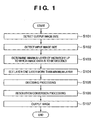
- a first embodiment is briefly explained with reference to a flowchart of Fig . 1 .
- step S101 an output image size is detected in step S101, an input image size is detected in step S102, then the process moves on to step S103.
- step S103 a minimum layer of hierarchy up to which image data is to be decided is determined from the output and input image sizes obtained in steps S101 and S102, then the process proceeds to step S104.
- step S104 a layer of hierarchy which is one layer more than the layer determined in step S103 (so that a larger image is decoded) is set.
- step S105 decoding processing is performed up to the layer of hierarchy which is set in step S104, and the process proceeds to step S106. Since an image which is larger than the required output image size is decoded due to the process in step S104, the resolution of the decoded image is reduced in step S106. A pre-filtering process is performed so that alias is not generated in this down sampling.
- step S107 ⁇ correction, color correction, format conversion, offset processing, and so on, are performed on the image of good quality obtained in step S106 in accordance with a device to which the image is outputted, then the processed image is outputted.
- Fig. 2 is a drawing exemplifying a hierarchy of a hierarchically coded image.
- a case of outputting a 160 (pixels) ⁇ 120 (pixels) image (horizontal ⁇ vertical) from image data of a 640 (pixels) ⁇ 480 (pixels) image is explained. Since an output image size corresponds to LL2 in Fig. 2, a layer of LL2 is obtained first.
- a decoded image of only LL2 is a distorted image including alias, thus a layer of hierarchy which is one layer more than the layer of LL2 is set in order to cancel alias of LL2.
- image data of 320 ⁇ 240 pixels corresponding to LL2, HL2, LH2, and HH2 is decoded. In this way, alias of LL2 is cancelled. Thereafter, a 160 (pixels) ⁇ 120 (pixels) image is obtained from the decoded 320 (pixels) ⁇ 240 (pixels) image using a sub-sampling filter, thereby obtaining an image of good quality.
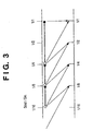
- Fig. 3 shows a relationship between the input/output size ratios and layers of hierarchy up to which image data is to be decoded.
- Sout When an output image size is denoted by Sout and an input image size is denoted by Sin, Sout/Sin is shown in the upper scale.
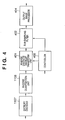
- Fig. 4 is a block diagram showing a functional configuration of a decoding apparatus according to the first embodiment.
- reference numeral 1107 denotes an entropy decoder
- reference numeral 1108 denotes an inverse quantization unit.
- An inverse discrete wavelet transform unit 401 is basically the same as the inverse discrete wavelet transform unit 1109 shown in Fig. 34 described as a prior art, but different in that the inverse discrete wavelet transform unit 401 can stop decoding processing in the middle of the decoding processing or stop the decoding operation partially in response to a control signal (will be described later).
- Reference numeral 402 denotes a sub-sampling filter for resolution conversion; 403, a controller for controlling hierarchical processing; and 404, an output image processor.
- the controller 403 determines a layer of hierarchy up to which image data is to be decoded on the basis of the input image size and the output image size, and controls the inverse discrete wavelet transform unit 401 and the sub-sampling filter 402. Since decoding of image data more than the necessary layer/layers is not needed, the controller 403 controls the inverse discrete wavelet transform unit 401 to stop the decoding processing in the middle of the decoding processing or to stop operation of an unnecessary processing unit/units. In this manner, it is possible to improve processing time, processing performance, and energy consumption.
- the controller 403 controls the sub-sampling filter 402 to perform resolution conversion processing of reducing the image size to equal to or less than 1/2 of the image data outputted from the inverse discrete wavelet transform unit 401.
- This process includes a pre-filtering process for removing alias caused by down sampling. However, this process by the sub-sampling filter 402 is not performed when all of the image data is outputted.
- the output image processor 404 performs various processes and conversions for outputting the image and outputs the processed image similarly to the image output unit 1110 in Fig. 34.
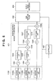
- Fig. 5 shows an internal configuration of the inverse discrete wavelet transform unit 401.
- This configuration differs from that shown in Fig. 37 in that it is possible to stop decoding processing in the middle of the processing, to partially stop the processing, or prevent the processing from being started under the control of the controller 403. Further, the data of the lowest resolution corresponding to LL2 is not outputted to the sub-sampling filter 402. This is because LL2 contains alias, and it is necessary to decode image data up to a layer of hierarchy which is one layer more than the layer of LL2. However, a case of outputting a simple image, such as a thumbnail image, which does not require quality, is not included in this case.
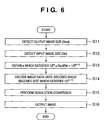
- an output image size (Sout) is detected in step S11, and an input image size (Sin) is detected in step S12.
- step S13 a layer (n) up to which image data is to be at least decoded is calculated using the equation (1) from the output image size (Sout) and the input image size (Sin) respectively obtained in steps S11 and S12.
- This process corresponds to the process in step S103 of Fig. 1. 1/2 n ⁇ Sout/Sin > 1/2 (n+1)
- step S14 a layer of hierarchy up to which image data is to be actually decoded is determined on the basis of "n" obtained in step S13 using the equation (2) and the image data is decoded, or the image data is decoded to become an input/output ratio expressed by the equation (2).
- This process corresponds to the process in steps S104 and S105 in Fig. 1. 1/2 (n-1) where n is an integer equal to or greater than 1.
- step S14 Since an image having a size which is larger than a necessary output image size is decoded in step S14, resolution conversion of accordingly reducing the resolution of the image is performed in step S15. At this time, pre-filtering process is performed to prevent generation of alias.
- step S16, ⁇ correction, color correction, format conversion, offset processing, and so on, are performed on the image obtained in step S15 in accordance with a device to which the image is outputted. The processed image is then outputted.
- FIG. 7 Another method of obtaining a layer of hierarchy up to which image data is to be decoded on the basis of an input/output image size ratio is explained with reference to Fig. 7.
- the apparatus configuration and a concept of hierarchy coding are the same as those described in the first embodiment, and thus the description of them are omitted. Further, the processes in Fig. 7 which are same as those shown Fig. 6 are referred to by the same step numbers.
- an output image size (Sout) is detected in step S11, and an input image size (Sin) is detected in step S12.
- step S23 an input/output image size ratio (X) is calculated using the equation (3) from the output image size (Sout) and the input image size (Sin) respectively obtained in steps S11 and S12.
- X Sin/Sout
- step S24 the maximum number (n) of layer/layers of hierarchy which can be excluded from decoding processing is determined using the equation (4) on the basis of the input/output image size ratio (X) obtained in step S23.
- n INT(log 2 X) INT(f(X)) in the equation (4) represents an operation of rounding down below the decimal place of a value obtained by the calculation of f(X).
- step S24 Since the number of layer/layers which can be excluded from the decoding processing is determined in step S24, the number of layer/layers, image data of which has to be decoded, is calculated based on the total number of layers of hierarchy of an input image, and further a layer up to which image data is actually decoded, that is one layer more than the necessary layer/layers, is calculated in step S25 using the equation (5), and an image is decoded so as to satisfy the condition.
- Number of Layer/Layers to Be Decoded Total Number of Layers - n + 1
- step S25 Since an image having a size which is larger than a necessary output image size is decoded in step S25, resolution conversion of accordingly reducing the resolution of the image is performed in step S15. At this time, pre-filtering process is performed to prevent generation of alias.
- step S16, ⁇ correction, color correction, format conversion, offset processing, and so on, are performed on the image obtained in step S15 in accordance with a device to which the image is outputted, then the processed image is outputted.
- a method of hierarchically decoding image data layer by layer and obtaining an image of a desired size by checking the size of the decoded image is explained with reference to Fig. 8.
- the apparatus configuration and a concept of hierarchy coding are the same as those described in the first embodiment, and thus the description of them are omitted. Further, the processes in Fig. 8 which are same as those shown Fig. 6 are referred to by the same step numbers.
- an output image size (Sout) is detected in step S11, and the process proceeds to step S32 where image data corresponding to the lowest layer of hierarchy out of layer/layers which has/have not been decoded is decoded.
- step S33 it is determined whether the size of the image decoded in step S32 is equal to or larger than the output image size (Sout). If Yes, the process moves to step S34, whereas if No, the process returns to step S32 and image data of another lowest layer is decoded. By the operation of steps S32 and S33, image data corresponding to an image having a size equal to or larger than the output image size is decoded.
- step S34 image data of one more layer is decoded in step S34. It should be noted that if the size of the image has reached to the input image size at this point, the process of step S34 is not performed.
- step S34 Since an image having a size which is larger than a necessary output image size is decoded in step S34, resolution conversion of accordingly reducing the resolution of the image is performed in step S15. At this time, pre-filtering process is performed to prevent generation of alias.
- step S16, ⁇ correction, color correction, format conversion, offset processing, and so on, are performed on the image obtained in step S15 in accordance with a device to which the image is outputted, then the processed image is outputted.
- a method of obtaining from a look up table (LUP) a layer of hierarchy up to which image data is to be decoded to obtain an image with no alias is explained.
- Fig. 9 is a block diagram illustrating a functional configuration of a decoding apparatus according to the fourth embodiment of the present invention.
- the configuration in Fig. 9 differs from that of Fig. 1 described in the first embodiment in which a LUP 1002 is added and can be referred by a controller 1001.
- Other elements are same as those in the first embodiment, and the explanation of them are omitted.
- the controller 1001 is basically the same as the controller 403 described in the first embodiment with reference to Fig. 4, but the controller 1001 is different from the controller 403 in that it stops decoding processing or partially stopping an operation by referring to the LUT 1002.
- the LUT 1002 transmits information on a layer/layers of hierarchy to be decoded based on, inter alia , the input/output image size information to the controller 1001.
- the type and/or structure of the LUT 1002 is not fixed as long as the function and purpose are same.
- the content of LUT 1002 is loaded at the start of the decoding processing.
- the contents of the LUT 1002 may be adaptively changed by determining the characteristics of a wavelet filter or the degree of effect of alias.
- the controller 1001 determines a layer of hierarchy up to which image data is to be decoded for obtaining an image with no alias from the input image size and the output image size by referring to the LUT 1002, and controls the inverse discrete wavelet transform unit 401 and the sub-sampling filter 402.
- an output image size (Sout) is detected in step S11, and an input image size (Sin) is detected in step S12.
- step S43 a layer of hierarchy up to which image data is to be decoded is determined by referring to the LUT 1002 based on the information obtained in steps S11 and S12.
- the LUT 1002 is preset so as to give a layer of hierarchy which is one layer more than the minimum layer of hierarchy necessary for obtaining an image of the designated output image size (e.g., so as to give an output as shown in Fig. 3).
- step S44 image data is decoded up to the layer obtained in step S43.
- step S44 Since an image having a size which is larger than a necessary output image size is decoded in step S44, then accordingly, resolution conversion of reducing the resolution of the image is performed in step S15. At this time, pre-filtering process is performed to prevent generation of alias.
- step S16, ⁇ correction, color correction, format conversion, offset processing, and so on, are performed on the image obtained in step S15 in accordance with a device to which the image is outputted. The processed image is then outputted.
- a fifth embodiment is aimed at performing encoding which gives no bad effect on image quality by alias when an image is encoded up to an intermediate layer of hierarchy.
- step S201 a transmission image size is detected.
- the size can be adaptively changed in accordance with a destination of an image, a media on which the image is to be recorded, or an operation mode. Then, the process proceeds to step S202 where an input image size is detected.
- step S203 a layer of hierarchy up to which necessary image data is to be transmitted is determined from the transmission image size and the input image size respectively determined in steps S201 and S202, and the process proceeds to step S204.
- step S204 a layer of hierarchy which is one layer more than the layer determined in step S203 (so that a larger image is coded) is set.
- step S205 encoding is performed up to the layer which is set in step S204, and the process proceeds to step S206.
- step S206 encoded image data is transmitted or recorded on a medium.
- Fig. 2 is a drawing exemplifying a hierarchy of a hierarchically coded image.
- a case of encoding and outputting a 160 (pixels) x 120 (pixels) image (horizontal x vertical) from image data of a 640 (pixels) x 480 (pixels) image is explained. Since the size of an image to be encoded and outputted corresponds to LL2 in Fig. 2, a layer of LL2 is obtained first.
- an encoded image of only LL2 is a distorted image including alias, thus a layer of hierarchy which is one layer more than the layer of LL2 is set in order to cancel alias of LL2.
- image data of 320 x 240 pixels corresponding to LL2, HL2, LH2, and HH2 is encoded.
- alias of LL2 is cancelled when decoding the image data by a decoder.
- the decoder performs resolution conversion, such as sampling a 160 (pixel) x 120 (pixel) image out of the 320 (pixel) x 240 (pixel) image using a sub-sampling filter, thereby an image of good quality can be obtained.
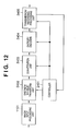
- Fig. 12 is a block diagram showing a functional configuration of an encoding apparatus according to the fifth embodiment.
- reference numeral 1101 denotes an image input processing unit; 2402, a discrete wavelet transform unit; 2403, a quantization unit; 2404, an entropy encoder; 2405, a transmission/recording processing unit; and 2401, a controller.
- the controller 2401 determines a layer of hierarchy up to which image data is to be encoded based on the input image size and the transmission image size, and controls the discrete wavelet transform unit 2402, the quantization unit 2403, the entropy encoder 2404, and the transmission/recording processing unit 2405.
- the controller 2401 obtains information from the transmission/recording processing unit 2405, but the present invention is not limited to this and, for instance, the information can be obtained from mode information of the system.
- the controller 2401 controls the discrete wavelet transform unit 2402 and the entropy encoder 2404 to stop their processing in the middle of the encoding processing or to stop operation of unnecessary processing unit/units. In this manner, it is possible to improve processing time, processing performance, and energy consumption.
- the quantization unit 2403 can be controlled so as to omit quantization processing of an unnecessary layer/layers or output 0s for the unnecessary layer/layers to intercept image data of unnecessary layer/layers.
- the transmission/recording processing unit 2405 formats the data of layer/layers to be transmitted, and output it.
- the data of unnecessary layer/layers is deleted by, inter alia, a cut-down process. A plurality of deleting methods of unnecessary data are described above, and at least one of them is to be performed.
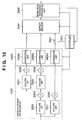
- Fig. 13 shows an internal configuration of the discrete wavelet transform unit 2402.
- Image data is inputted to a low pass filter 2503 for analysis (referred to as “analysis LPF”, hereinafter) for band division and to a high pass filter 2501 for analysis (referred to as “analysis HPF”, hereinafter) for band division, and separated into a low frequency band signal and a high frequency band signal.
- analysis LPF low pass filter
- HPF high pass filter
- the band width of each signal is a half of the band width of the original image data
- the down samplers 2502 and 2504 samples the signals.
- the high frequency component signal is outputted to the quantization unit 2403.
- the low frequency component signal is further recursively processed by an analysis HPF 2505, an analysis LPF 2507, and down samplers 2506 and 2508.
- a case of three-hierarchy output by two cycles of processing is shown.
- the concept of three-layer hierarchy is shown in Fig. 38.
- data corresponding to HL1, LH1, HH1 shown in Fig. 38 is obtained by the analysis HPF 2501 and the down sampler 2502, and data corresponding to LL1 is obtained by the analysis LPF 2503 and the down sampler 2504.
- the LL1 is recursively processed, and data corresponding to HL2, LH2, HH2 in Fig. 38 is obtained by the analysis HPF 2505 and the down sampler 2506, and data corresponding to LL2 in Fig. 38 is obtained by the analysis LPF 2507 and the down sampler 2508.
- the transmission/recording processing unit 2405 When the data of the all layers of hierarchy is not needed, the transmission/recording processing unit 2405 outputs that information to the controller 2401.
- the controller 2401 controls so that data of an unnecessary layer/layers of hierarchy is not encoded among each frequency band data.
- a determination algorithm is the difference between the fifth embodiment and the conventional configuration shown in Fig. 36, and the algorithm is for determining to, inter alia, stop encoding processing in the middle of the encoding processing, partially stop the processing, or prevent the encoding processing from being started. Since data in the fifth embodiment is obtained by encoding data of at least one more layer of hierarchy comparing to the conventional case, encoding of image data of only the lowest layer of hierarchy is not included in the fifth embodiment, and at least image data of the lowest and the second lowest layers has to be encoded. Therefore, a switch 2601 in Fig. 13 controls image data of a layer of hierarchy except those layers. However, a case of outputting a simple image, such as a thumbnail image, which does not require quality is not included in this case.
- Data of respective frequency bands is quantized by the quantization units 2403a to 2403c corresponding to the respective bands, encoded by the entropy encoder 2404 for each frequency band, then outputted from the transmission/recording processing unit.
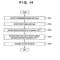
- a transmission image size (Sout) is detected in step S51, and an input image size (Sin) is detected in step S52.
- step S53 a layer (n) up to which image data is to be at least encoded is calculated using the equation (6) from the transmission image size (Sout) and the input image size (Sin) respectively obtained in steps S51 and S52.
- This process corresponds to the process in step S203 of Fig. 11. 1/2 n ⁇ Sout/Sin > 1/2 (n+1)
- step S54 a layer of hierarchy up to which image data is to be actually encoded is determined on the basis of "n" obtained in step S53 using the equation (7) and the image data is encoded.
- This process corresponds to the process in steps S204 and S205 in Fig. 11. 1/2 (n-1) where n is an integer equal to or greater than 1
- step S55 encoded image data obtained in step S54 is transmitted or recorded on a medium.
- a sixth embodiment another method of obtaining a layer of hierarchy up to which image data is to be encoded on the basis of an input/output image size ratio is explained with reference to Fig. 15.
- the apparatus configuration and a concept of hierarchy coding are the same as those described in the fifth embodiment, and thus the description of them are omitted. Further, the processes in Fig. 15 which are same as those shown Fig. 14 are referred to by the same step numbers.
- a transmission image size (Sout) is detected in step S51, and an input image size (Sin) is detected in step S52.
- step S63 an input/output image size ratio (X) is calculated using the equation (8) from the transmission image size (Sout) and the input image size (Sin) respectively obtained in steps S51 and S52.
- X Sin/Sout
- step S64 the maximum number of layer/layers of hierarchy which can be excluded from encoding processing is determined using the equation (9) on the basis of the input/output image size ratio (X) obtained in step S63.
- n INT(log 2 X) INT(f(X)) in the equation (9) represents an operation of rounding down below the decimal place of a value obtained by the calculation of f(X).
- step S64 Since the number of layer/layers which can be excluded from the encoding processing is determined in step S64, the number of layer/layers, image data of which has to be encoded, is calculated based on the total number of layers of hierarchy of an input image, and further a layer up to which image data is actually encoded, that is one layer more than the necessary layer/layers, is calculated in step S65 using the equation (10), and image data is encoded so as to satisfy the condition.
- Number of Layer/Layers to Be Encoded Total Number of Layers - n + 1
- step S55 encoded image data obtained in step S65 is transmitted or recorded on a medium.
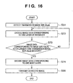
- a method of hierarchically encoding image data layer by layer and obtaining an image of a desired size by checking the size of the encoded image is explained with reference to Fig. 16.
- the apparatus configuration and a concept of the hierarchy coding are the same as those described in the fifth embodiment, and thus the description of them are omitted. Further, the processes in Fig. 16 which are same as those shown Fig. 14 are referred to by the same step numbers.
- a transmission image size (Sout) is detected in step S51, and the process proceeds to step S72 where image data corresponding to the lowest layer of hierarchy out of layer/layers which has/have not been encoded is encoded.
- step S73 it is determined whether the size of the image encoded in step S72 is equal to or larger than the transmission image size (Sout). If Yes, the process moves to step S74, whereas if No, the process returns to step S72 and image data of another lowest layer is encoded. By the operation of steps S72 and S73, image data corresponding to an image having a size equal to or larger than the transmission image size is encoded.
- step S74 image data of one more layer is encoded in step S74. It should be noted that if the size of the image has reached to the input image size at this point, the process of step S74 is not performed.
- step S55 encoded image data obtained in step S54 is transmitted or recorded on a medium.
- a method of obtaining from a look up table (LUP) a layer of hierarchy up to which image data is to be encoded to obtain an image with no alias is explained.
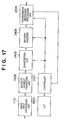
- Fig. 17 is a block diagram illustrating a functional configuration of an encoding apparatus according to the eighth embodiment of the present invention.
- the configuration in Fig. 17 differs from that of Fig. 12 described in the fifth embodiment in which a LUP 2602 is added and can be referred by a controller 2401.
- Other elements are same as those in the fifth embodiment, and the explanation of them are omitted.
- the type and/or structure of the LUT 2602 is not fixed as long as the function and purpose are same.
- the content of LUT 2602 is loaded at the start of the encoding processing.
- the contents of the LUT 2602 may be adaptively changed by determining the characteristics of a wavelet filter or the degree of effect of alias .
- the controller 2401 determines a layer of hierarchy up to which image data is to be encoded for obtaining an image with no alias from the input image size and the transmission image size by referring to the LUT 2602, and controls the discrete wavelet transform unit 2402, the quantization unit 2403, the entropy encoder 2404 and the transmission/recording processing unit 2405.
- a transmission image size (Sout) is detected in step S51, and an input image size (Sin) is detected in step S52.
- a layer of hierarchy up to which image data is to be encoded is determined by referring to the LUT 2602 based on the information obtained in steps S51 and S52.
- the LUT 2602 is preset so as to give a layer of hierarchy which is one layer more than the minimum layer of hierarchy necessary for obtaining an image of the designated transmission image size (e.g., so as to give an output as shown in Fig. 3).
- step S84 image data is encoded up to the layer obtained in step S83.
- step S55 encoded image data obtained in step S84 is transmitted or recorded on a medium.
- effects of alias are determined and information on a layer/layers of hierarchy to be encoded is obtained from LUT.
- LUT information on a layer/layers of hierarchy to be encoded
- the present invention can be applied to all of the components or to a luminance component to which the present invention is effective.
- the present invention is realized as an encoding apparatus and a decoding apparatus adopting hierarchical coding processing, and the present invention is especially effective to an apparatus which outputs an image of up to an intermediate layer of hierarchy, and an apparatus which converts color resolution.
- the embodiments a case of adopting a discrete wavelet transform method which conform to JPEG2000 is explained.
- FIG. 19 A configuration of a discrete wavelet transform unit according to the ninth embodiment is explained with reference to the block diagram of Fig. 19.
- elements which operate similarly to those shown in Figs. 35 and 36 are referred to by the same reference numerals, and explanation of them are omitted.
- Reference numerals 101 and 103 denote LPF as pre-filters, and reference numeral 102 and 104 denote subtractors.
- An input image signal enters the LPF 101 and the subtractor 102.
- the image signal entered the LPF 101 is limited its frequency (step S301), then inputted to the analysis LPF 1203 of the wavelet transform unit similarly to the conventional transform unit. Since the analysis LPF 1203 has broad characteristics, down sampling by the down sampler 1204 causes alias.
- LPF 101 functions as a pre-filter and restrains in advance a frequency component which causes alias.
- the LPF 101 is designed to have characteristics for restraining and cutting frequency components of the nyquist frequency and higher frequencies so as to prevent alias defined by a sampling theorem for its utilization purpose. The characteristics depend on imaging characteristics of the whole system, and they should be adjusted to the optimum characteristics.
- an output from the subtractor 102 is inputted to the analysis HPF 1201.
- the subtractor 102 subtracts an output signal of the LPF 101 from the input image signal and outputs (1 - pre-filter) signal (step S302).
- the subtraction process can achieve an effect similar to a HPF, as well as realize no gain and flat frequency characteristics together with the output from the LPF 101.
- Fig. 21 shows a state that signals which pass through the LPF 101 and the HPF (1 - LPF 101) respectively drop near nyquist frequency in good balance.
- the low frequency component signal which passed through the analysis LPF 1203 is down-sampled by the down sampler 1204, and outputted as a low frequency component of the first layer of hierarchy (i.e., data corresponding to LL1).
- the high frequency component signal which passed through the analysis HPF 1201 is down-sampled by the down sampler 1202, and outputted as a high. frequency component of the first layer of hierarchy (i.e., data corresponding to HL1, LH1, and HH1 in Fig. 38) (step S303).
- step S304 whether or not image data has undergone wavelet transform processing up to a preset layer of hierarchy is determined, and if NO, the process returns to step S301 where the similar processes as described above are repeated.
- image data is layered by recursively performing the above processes on the low frequency component. More specifically, the output from the down sampler 1204 (data corresponding to LL1 which is a low frequency component of the first layer of hierarchy) is further inputted to the LPF 103 as a pre-filter (step S301), and its output is further inputted to the second analysis LPF 1207 where a conventional process is performed.
- the component which causes alias is restrained and/or removed by the LPF 103 at this time, thus an alias component is not generated.
- the frequency characteristics of the LPF 103 has characteristics to restrain and/or remove alias caused by the analysis LPF 1207 and the down sampler 1208.
- an output from the subtractor 104 is inputted.
- the subtractor 104 subtracts an output signal of the LPF 103 from the low frequency component signal outputted from the down sampler 1204, and outputs the difference (step S302).
- the subtraction process can achieve an effect similar to a HPF, as well as realize no gain and flat frequency characteristics together with the output from the LPF 103 (step S303).
- the low frequency component signal which passed through the analysis LPF 1207 is down-sampled by the down sampler 1208, and outputted as a low frequency component of the second layer of hierarchy (i.e., data corresponding to LL2 in Fig. 38).
- the high frequency component signal which passed through the analysis HPF 1205 is down-sampled by the down sampler 1206, and outputted as a high frequency component of the second layer of hierarchy (i.e., data corresponding to HL2, LH2, and HH2 in Fig. 38).
- step S304 When it is determined in step S304 that wavelet transform of layering image data up to a preset layer is finished, the process proceeds to step S305 where a signal of each layer is quantized.
- step S305 undergoes entropy coding which compresses the data by using its redundancy (step S306). Thereafter, the compressed data is formatted in accordance with an output format, and transmitted or outputted to a recording system in step S307.
- step S305 to step S307 can be performed by using structures similarly to the quantization unit 1103, the entropy encoder 1104, and the transmission/recording processing unit 1105 shown in Fig. 34 described in the Background of the Invention.
- the ninth embodiment adopts octave division, the relationship between the cutoff frequencies of the LPF 101 and LPF 103 is also octave. Because the down sampler 1204 makes the sampling frequencies of an image have octave relationship, same FIR filters can be used as the LPF 101 and LPF 103 in the configuration.
- each LPF when the fact that the frequency band varies for each image is considered, it is also possible to design each LPF to have optimum characteristics for processing an image delicately so as to correspond to respective frequency band and/or improving encoding efficiency. Especially if the highest layer of hierarchy (high frequency component) is not encoded or decoded, it is possible to restrain and remove an effect of alias to its maximum by putting more weight on low frequency bandpass characteristics of LPFs.
- Fig. 22 shows a configuration example of a discrete wavelet transform unit according to the modification.
- elements, which perform similar processes as those shown in Fig. 19, are referred to by the same reference numerals and explanation of them is omitted.
- Fig. 22 is different from the ninth embodiment in which a switch 301 and memory 304 are added.
- An input image signal enters from an a terminal of the switch 301, and inputted to a LPF 302 and the subtractor 303.
- the LPF 302 performs band restriction for restraining and removing an alias component on the image signal, and outputs the processed image signal via the analysis LPF 1203 and the down sampler 1204 as a low frequency component signal.
- a subtractor 303 functions as a HPF by taking a difference between the input image signal and the output from the LPF 302, and its output signal is outputted as a high frequency component signal through the analysis HPF 1201 and the down sampler 1202.
- the high frequency component signal is outputted to the next configuration element.
- the low frequency component signal is temporarily stored in the memory 304 to be recursively used and, in the next hierarchical layering processing, inputted again from the memory 304 to the LPF 302 and the subtractor 303 via a terminal b of the switch 301.
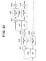
- Fig. 23 is a block diagram illustrating a configuration of a discrete wavelet transform unit according to the tenth embodiment.
- LPFs are used as pre-filters in the ninth embodiment, whereas HPFs are used as shown in Fig. 23 in the tenth embodiment.
- elements which operate similarly to those shown in Figs. 35, 36 and 19 are referred to by the same reference numerals, and explanation of them is omitted.
- Reference numerals 502 and 504 denote HPFs as pre-filters, and reference numerals 501 and 503 denote subtractors.
- An input image signal enters the HPF 502 and the subtractor 501.
- the image signal entered the HPF 502 is limited its frequency (step S301), then inputted to the analysis HPF 1201 of the wavelet transform unit similarly to the conventional transform unit. Since the analysis HPF 1201 has broad characteristics, down sampling by the down sampler 1202 causes alias. However, the HPF 502 functions as a pre-filter and restrains in advance a frequency component which causes alias.
- the HPF 502 is designed to have characteristics for restraining and cutting frequency components of the nyquist frequency and lower frequencies so as to prevent alias defined by a sampling theorem for its utilization purpose. The characteristics depend on imaging characteristics of the whole system, and they should be adjusted to the optimum characteristics.
- the subtractor 501 subtracts an output signal of the HPF 502 from the input image signal and outputs (1 - pre-filter) signal (step S302).
- the subtraction process can achieve an effect similar to a LPF, as well as realize no gain and flat frequency characteristics together with an output from the HPF 502.
- Fig. 24 shows a state that signals which pass through the LPF (1 - HPF 502) and the HPF 502 respectively drop near nyquist frequency in good balance.
- the high frequency component signal which passed through the analysis HPF 1201 is down-sampled by the down sampler 1202, and outputted as a high frequency component of the first layer of hierarchy (i.e., data corresponding to HL1, LH1, and HH1 in Fig. 38).
- the low frequency component signal which passed through the analysis LPF 1203 is down-sampled by the down sampler 1204, and outputted as a low frequency component of the first layer of hierarchy (i.e., data corresponding to LL1) (step S303).
- step S304 whether or not image data has undergone wavelet transform processing up to a preset layer of hierarchy is determined, and if NO, the process returns to step S301 where the similar processes as described above are repeated.
- image data is layered by recursively performing the above processes on the low frequency component. More specifically, the output from the down sampler 1204 (data corresponding to LL1 which is a low frequency component of the first layer of hierarchy) is further inputted to the HPF 504 as a pre-filter (step S301), and its output is further inputted to the second analysis HPF 1205 where a conventional process is performed.
- the component which causes alias is restrained and/or removed by the HPF 504 at this time, thus an alias component is not generated.
- the frequency characteristics of the HPF 504 has characteristics to restrain and/or remove alias caused by the analysis HPF 1205 and the down sampler 1206.
- an output from the subtractor 503 is inputted.
- the subtractor 503 subtracts an output signal of the HPF 504 from the low frequency component signal outputted from the down sampler 1204, and outputs the difference (step S302).
- the subtraction process can achieve an effect similar to a LPF, as well as realize no gain and flat frequency characteristics together with an output from the HPF 504.
- the high frequency component signal which passed through the analysis HPF 1205 is down-sampled by the down sampler 1206, and outputted as a high frequency component of the second layer of hierarchy (i.e., data corresponding to HL2, LH2 and HH2 in Fig. 38).
- the low frequency component signal which passed through the analysis LPF 1207 is down-sampled by the down sampler 1208, and outputted as a low frequency component of the second layer of hierarchy (i.e., data corresponding to LL2 in Fig. 38) (step S303).
- step S304 The processes subsequent to YES in step S304 are the same as those explained in the ninth embodiment, which explanation is omitted.
- the relationship between the cutoff frequencies of the HPF 502 and HPF 504 is also octave. Because the down sampler 1204 makes the sampling frequencies of an image have octave relationship, same FIR filters can be used as the HPF 502 and HPF 504 in the configuration.
- each HPF When the fact that the frequency band varies for each image is considered, it is also possible to design each HPF to have optimum characteristics for processing an image delicately so as to correspond to respective frequency band and/or improving encoding efficiency. Especially if the highest layer of hierarchy (high frequency component) is not encoded or decoded, it is possible to restrain and remove an effect of alias to its maximum by putting more weight on low frequency bandpass characteristics of HPFs.
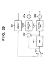
- Fig. 25 shows a configuration example of a discrete wavelet transform unit according to the modification.
- elements which perform similar processes as those shown in Fig. 23 are referred to by the same reference numerals and explanation of them is omitted.
- Fig. 25 is different from the tenth embodiment in which a switch 301 and memory 304 are added.
- An input image signal enters from an a terminal of the switch 301, and inputted to a HPF 601 and the subtractor 602.
- the HPF 601 performs band restriction for restraining and removing an alias component on the image signal, and outputs the processed image signal via the analysis HPF 1201 and the down sampler 1202 as a high frequency component signal.
- a subtractor 602 functions as a LPF by taking a difference between the input image signal and the output from the HPF 601, and its output signal is outputted as a low frequency component signal through the analysis LPF 1203 and the down sampler 1204.
- the low frequency component signal is temporarily stored in the memory 304 to be recursively used and, in the next hierarchical layering processing, inputted again from the memory 304 to the HPF 601 and the subtractor 602 via a terminal b of the switch 301. By performing this recursive processing up to a predetermined layer of hierarchy, layers are formed.
- Fig. 26 is a block diagram illustrating a configuration of a discrete wavelet transform unit according to the eleventh embodiment.
- LPFs are used in the ninth embodiment and HPFs are used in the tenth embodiment as pre-filters, whereas both LPFs and HPFs are used as shown in Fig. 26 in the eleventh embodiment.
- elements which operates similarly to those shown in Figs. 35, 36, 19, and 23 are referred to by the same reference numerals, and explanation of them is omitted.
- Reference numerals 701 and 703 denote HPFs as pre-filters, and reference numeral 702 and 704 denote LPFs.
- An input image signal is limited its frequency by the HPF 701 (step S301), then inputted to the analysis HPF 1201 of the wavelet transform unit similarly to the conventional transform unit. Since the analysis HPF 1201 has broad characteristics, down sampling by the down sampler 1202 causes alias. However, the HPF 701 functions as a pre-filter and restrains in advance a frequency component which causes alias.
- the HPF 701 is designed to have characteristics for restraining and cutting frequency components of the nyquist frequency or lower frequencies so as to prevent alias defined by a sampling theorem for its utilization purpose. The characteristics depend on imaging characteristics of the whole system, so that they should be adjusted to the optimum characteristics.
- the input image signal also enters the LPF 702 and is limited its frequency (corresponds to obtaining (1 - pre-filter) signal in step S302), then inputted to the analysis LPF 1203 of the wavelet transform unit similarly to the conventional transform unit. Since the analysis LPF 1203 has broad characteristics, down sampling by the down sampler 1204 causes alias. However, the LPF 702 functions as a pre-filter and restrains in advance a frequency component which causes alias. The LPF 702 is designed to have characteristics for restraining and cutting frequency components of the nyquist frequency and higher frequencies so as to prevent alias defined by a sampling theorem for its utilization purpose. The characteristics depend on imaging characteristics of the whole system, and they should be adjusted to the optimum characteristics.
- the frequency band restriction process by the LPF 702 can be considered as the process of step S301.
- the frequency band restriction process by the HPF 701 can be considered as the process of acquiring a (1 - pre-filter) signal performed in step S302.
- Fig. 27 shows a state that signals which pass through the LPF 702 and the HPF 701 respectively drop near nyquist frequency in good balance.
- the high frequency component signal which passed through the analysis HPF 1201 is down-sampled by the down sampler 1202, and outputted as a high frequency component of the first layer of hierarchy (i.e., data corresponding to HL1, LH1, and HH1 in Fig. 38).
- the low frequency component signal which passed through the analysis LPF 1203 is down-sampled by the down sampler 1204, and outputted as a low frequency component of the first layer of hierarchy (i.e., data corresponding to LL1) (step S303).
- step S304 whether or not image data has undergone wavelet transform processing up to a preset layer of hierarchy is determined, and if NO, the process returns to step S301 where the similar processes as described above are repeated.
- image data is layered by recursively performing the above processes on the low frequency component. More specifically, the output from the down sampler 1204 (data corresponding to LL1 which is a low frequency component of the first layer of hierarchy) is further inputted to pre-filters, the HPF 703 and LPF 704 (steps S301 and S302), and an output of the HPF 703 is further inputted to the second analysis HPF 1205 where a conventional process is performed.
- the component which causes alias is restrained and/or removed by the HPF 703 at this time, thus an alias component is not generated.
- the frequency characteristics of the HPF 703 has characteristics to restrain and/or remove alias caused by the analysis HPF 1205 and the down sampler 1206. To the analysis LPF 1207, an output from LPF 704 is inputted.
- the high frequency component signal which passed through the analysis HPF 1205 is down-sampled by the down sampler 1206, and outputted as a high frequency component of the second layer of hierarchy (i.e., data corresponding to HL2, LH2 and HH2 in Fig. 38).
- the low frequency component signal which passed through the analysis LPF 1207 is down-sampled by the down sampler 1208, and outputted as a low frequency component of the second layer of hierarchy (i.e., data corresponding to LL2 in Fig. 38) (step S303).
- the eleventh embodiment adopts octave division, the relationship between the cutoff frequencies of the HPFs 701 and 703, and of the LPFs 702 and 704 are also octave. Because the down sampler 1204 makes the sampling frequencies of an image have octave relationship, same FIR filters can be used as the HPFs 701 and 703, and the LPFs 702 and 704 in the configuration.
- each HPF and LPF it is also possible to design each HPF and LPF to have optimum characteristics for processing an image delicately so as to correspond to respective frequency band and/or improving encoding efficiency.
- the highest layer of hierarchy high frequency component
- Fig. 28 shows a configuration example of a discrete wavelet transform unit according to the modification.
- elements which perform similar processes as those shown in Fig. 26 are referred to by the same reference numerals and explanation of them is omitted.
- Fig. 28 is different from the eleventh embodiment in which a switch 301 and memory 304 are added.
- An input image signal enters from an a terminal of the switch 301, and inputted to HPF 901 and LPF 902.
- the HPF 901 and LPF 902 perform band restriction for restraining and removing an alias component on the image signal.
- An output of the HPF 901 is outputted via the analysis HPF 1201 and the down sampler 1202 as a high frequency component signal.
- the output of the LPF 902 is outputted as a low frequency component signal through the analysis LPF 1203 and the down sampler 1204.
- the low frequency component signal is temporarily stored in the memory 304 to be recursively used and, in the next hierarchical layering processing, inputted again from the memory 304 to the HPF 901 and the LPF 902 via a terminal b of the switch 301.
- layers are formed.
- an image signal consists of a plurality of components
- the present invention is applied to all of the components or to a luminance signal to which it is considered effective to apply the present invention.
- conversion processing 4:2:2, 4:1:1, 4:2:0, or 4:1:0. This can be easily realized by using a hierarchical structure.
- Fig. 29 is a block diagram illustrating a configuration of an decoder according to the twelfth embodiment of the present invention.
- elements which operates similarly to those shown in Fig. 34 explained in the Background of the Invention are referred to by the same reference numerals, and explanation of them is omitted.
- Reference numeral 202 denotes a sub-sampling filter (or, low pass filter or down sampling filter) for removing alias; 203, a controller for controlling insertion of the sub-sampling filter 202; and 204, an output image processor.
- a sub-sampling filter or, low pass filter or down sampling filter
- the controller 203 determines whether decoding processing is performed for all the layers of hierarchy of the encoded image data, and controls whether to make the image data pass through the sub-sampling filter 202 or processed.
- the sub-sampling filter 202 performs processes including a pre-filter process for removing alias caused by down sampling.
- the output image processor 204 performs various processes and conversions for outputting an image, and outputs the processed image.
- Fig. 30 shows an internal configuration of the sub-sampling filter 202.
- image data passes through the sub-sampling filter 202 without being processed.
- a sub-sampling process is performed to remove an alias component included in the image data, thereby an image of good quality is outputted.
- a case of outputting a simple image, such as a thumbnail image which does not require high image quality may be excluded from the above operation.
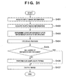
- step S401 input image information including an image size and information on encoded layer/layers of hierarchy of an image to be inputted to the decoding apparatus is acquired.
- step S402 output image information including an output image size is acquired, and the process moves to step S403.
- step S403 a layer of hierarchy up to which image data is to be decoded is determined on the basis of the information, such as the input image size and the output image size obtained in steps S401 and S402, respectively, then the process proceeds to step S404.
- step S404 decoding processing is performed up to the layer determined in step S403.
- step S405. whether or not all of the layers of image data were decoded in step S404 is determined in step S405. If Yes, the process proceeds to step S407, whereas if No, the process goes to step S406.
- the decoded image signal includes alias, and an alias component which is not cancelled because no signal component outputted from a HPF included in the image data is synthesized is restrained and removed using the sub-sampling filter 202. After filtering the decoded image data, the process proceeds to step S407.
- step S406 If all the layers of hierarchy of encoded image data were decoded, no alias component remains. Accordingly, the process in step S406 is not necessary, and the process directly moves to step S407 without performing the process in step S406.
- step S407 ⁇ correction, color correction, format conversion, offset process, and so on, which are suitable for a destination of the obtained image of good quality are performed, thereby outputting the image of demanded good quality.
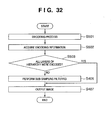
- the decoder of the thirteenth embodiment has the same configuration as that described in Figs. 29 and 30, however, a process in the controller 203 is different from that described in the twelfth embodiment. Decoding processing is explained with reference to a flowchart in Fig. 32 below.
- the twelfth embodiment it is determined up to which layer of hierarchy image data is to be decoded in decoding processing. In the thirteenth embodiment, whether to insert a sub-sampling filter 202 or not is determined based on the layer of hierarchy up to which image data was encoded in encoding processing.
- step S501 in Fig. 32 all the coded image data is decoded.
- step S502 encoding information on whether all the layers of hierarchy of the image data were encoded after the image data was layered hierarchically is acquired.
- step S503 whether or not all the layers of the image data were encoded is determined based on the information acquired in step S502. If No, the process moves onto step S406, whereas if Yes, the process goes to S407.
- the decoded image signal includes alias.
- an alias component which is not cancelled because no signal component outputted from a HPF included in the image data is synthesized is restrained and removed using the sub-sampling filter 202. After filtering the decoded image data, the process proceeds to step S407.
- step S406 If all the layers of hierarchy of image data were encoded, no alias component remains. Accordingly, the process in step S406 is not necessary, and the process directly moves to step S407 without performing the process in step S406.
- step S407 ⁇ correction, color correction, format conversion, offset process, and so on, which are suitable for a destination of the obtained image of good quality are performed, thereby outputting the image of demanded good quality.
- whether or not to insert the sub-sampling filter 202 is determined in accordance with whether or not all the layers of hierarchy of the image data were encoded in encoding processing in the thirteenth embodiment. In addition to this control, it is also possible to control the insertion of the filter 202 on the basis of a layer up to which the image data is decoded in decoding processing as described in the twelfth embodiment.
- the decoder of the fourteenth embodiment has the same configuration as that described in Figs. 29 and 30, however, a process in the controller 203 is different from that described in the twelfth and thirteenth embodiments. Decoding processing is explained with reference to a flowchart in Fig. 33 below.
- a layer of hierarchy up to which image data is to be decoded is determined in the twelfth embodiment, and a layer of hierarchy up to which image data was encoded is determined in the thirteenth embodiment.
- a layer of hierarchy up to which image data was encoded is determined in the thirteenth embodiment.
- the fourteenth embodiment relates to insertion of the sub-sampling filter 202 determined at the time of receiving an image data or reproducing image data from a medium.
- image data is received or reproduced from a medium or the like up to a predetermined hierarchy, and decoded.
- step S602 information on whether or not received/reproduced image data contains all the layers of hierarchy is received at the time of reception or reproduction from, e.g., a medium of the image data. Then, in step S603, whether or not all the layers of the image data are received/reproduced is determined based on the information acquired in step S602. If No, the process moves to step S406, whereas if Yes, the process proceeds to step S407.
- the image data is decoded to an intermediate layer of hierarchy.
- the decoded image signal includes alias, and an alias component which is not cancelled because no signal component outputted from a HPF included in the image data is synthesized is restrained and removed using the sub-sampling filter 202. After filtering the decoded image data, the process proceeds to step S407.
- step S406 If all the layers of hierarchy of encoded image data were received/reproduced, no alias component remains. Accordingly, the process in step S406 is not necessary, and the process directly moves to step S407 without performing the process in step S406.
- step S407 ⁇ correction, color correction, format conversion, offset process, and so on, which are suitable for a destination of the obtained image of good quality are performed, thereby outputting the image of demanded good quality.
- the sub-sampling filter 202 is inserted when image data is decoded up to an intermediate layer of hierarchy.
- a case of outputting a simple image, such as a thumbnail image, which does not require high image quality may be excluded from the above operation.
- an image signal consists of a plurality of components
- the present invention is applied to all of the components or to a luminance signal to which it is considered effective to apply the present invention.
- the present invention can be applied to a system constituted by a plurality of devices (e.g., host computer, interface, scanner, camera head, communication device) or to an apparatus comprising a single device (e.g., facsimile machine, digital still camera, digital video camera).
- a plurality of devices e.g., host computer, interface, scanner, camera head, communication device
- an apparatus comprising a single device (e.g., facsimile machine, digital still camera, digital video camera).
- the object of the present invention can also be achieved by providing a storage medium storing program codes for performing the aforesaid processes to a computer system or apparatus (e.g., a personal computer), reading the program codes, by a CPU or MPU of the computer system or apparatus, from the storage medium, then executing the program.
- a computer system or apparatus e.g., a personal computer
- the program codes read from the storage medium realize the functions according to the embodiments, and the storage medium storing the program codes constitutes the invention.
- the storage medium such as a floppy disk, a hard disk, an optical disk, a magneto-optical disk, CD-ROM, CD-R, a magnetic tape, a non-volatile type memory card, and ROM
- computer network such as LAN (local area network) and WAN (wide area network)
- LAN local area network
- WAN wide area network
- the present invention includes a case where an OS (operating system) or the like working on the computer performs a part or entire processes in accordance with designations of the program codes and realizes functions according to the above embodiments.
- the present invention also includes a case where, after the program codes read from the storage medium are written in a function expansion card which is inserted into the computer or in a memory provided in a function expansion unit which is connected to the computer, CPU or the like contained in the function expansion card or unit performs a part or entire process in accordance with designations of the program codes and realizes functions of the above embodiments.
- the storage medium stores program codes corresponding to any one of the flowcharts 1, 6-8, 10, 11, 14-16, 18, 20, and 31-33 described in the embodiments.
Landscapes
- Engineering & Computer Science (AREA)
- Multimedia (AREA)
- Signal Processing (AREA)
- Physics & Mathematics (AREA)
- General Physics & Mathematics (AREA)
- Theoretical Computer Science (AREA)
- Compression Or Coding Systems Of Tv Signals (AREA)
- Compression Of Band Width Or Redundancy In Fax (AREA)
Applications Claiming Priority (4)
| Application Number | Priority Date | Filing Date | Title |
|---|---|---|---|
| JP2002309901A JP2004147095A (ja) | 2002-10-24 | 2002-10-24 | 復号方法 |
| JP2002309902A JP4125090B2 (ja) | 2002-10-24 | 2002-10-24 | 符号化方法及び装置 |
| JP2002309902 | 2002-10-24 | ||
| JP2002309901 | 2002-10-24 |
Publications (2)
| Publication Number | Publication Date |
|---|---|
| EP1473675A2 true EP1473675A2 (fr) | 2004-11-03 |
| EP1473675A3 EP1473675A3 (fr) | 2010-02-10 |
Family
ID=32179094
Family Applications (1)
| Application Number | Title | Priority Date | Filing Date |
|---|---|---|---|
| EP03256675A Withdrawn EP1473675A3 (fr) | 2002-10-24 | 2003-10-23 | Conversion de résolution d'une image numérique par codage et décodage hiérarchique |
Country Status (2)
| Country | Link |
|---|---|
| US (4) | US7558441B2 (fr) |
| EP (1) | EP1473675A3 (fr) |
Families Citing this family (13)
| Publication number | Priority date | Publication date | Assignee | Title |
|---|---|---|---|---|
| US7382922B2 (en) * | 2003-07-11 | 2008-06-03 | Canon Kabushiki Kaisha | Creation of remarkable regions in a digital image |
| JP4649859B2 (ja) * | 2004-03-25 | 2011-03-16 | ソニー株式会社 | 信号処理装置および方法、記録媒体、並びにプログラム |
| US7800577B2 (en) * | 2004-12-02 | 2010-09-21 | Sharp Laboratories Of America, Inc. | Methods and systems for enhancing display characteristics |
| US7525583B2 (en) * | 2005-02-11 | 2009-04-28 | Hewlett-Packard Development Company, L.P. | Decreasing aliasing in electronic images |
| US20070152855A1 (en) * | 2006-01-03 | 2007-07-05 | Bbe Sound Inc. | Digital remastering system and method |
| JP4525634B2 (ja) * | 2006-05-18 | 2010-08-18 | パナソニック株式会社 | デジタル放送受信装置 |
| JP4129694B2 (ja) * | 2006-07-19 | 2008-08-06 | ソニー株式会社 | 情報処理装置および方法、プログラム、並びに記録媒体 |
| US20090109491A1 (en) * | 2007-10-30 | 2009-04-30 | Microsoft Corporation | Raw-quality processing of non-raw images |
| JP4850818B2 (ja) * | 2007-11-30 | 2012-01-11 | キヤノン株式会社 | 画像処理装置およびその方法 |
| JP2012249145A (ja) * | 2011-05-30 | 2012-12-13 | Sony Corp | 画像処理装置、画像処理方法及びプログラム |
| FR2981781A1 (fr) * | 2011-10-19 | 2013-04-26 | France Telecom | Codage hierarchique perfectionne |
| KR20140088924A (ko) * | 2012-12-14 | 2014-07-14 | 삼성전자주식회사 | 이미지 데이터 표시장치 및 방법 |
| US11102487B2 (en) * | 2019-08-30 | 2021-08-24 | Adobe Inc. | Image resampling for DCT based image encoding formats using memory efficient techniques |
Family Cites Families (32)
| Publication number | Priority date | Publication date | Assignee | Title |
|---|---|---|---|---|
| JP2933457B2 (ja) | 1993-02-18 | 1999-08-16 | 日本電気株式会社 | ウェーブレット変換符号化方法 |
| US5845015A (en) * | 1995-10-12 | 1998-12-01 | Sarnoff Corporation | Method and apparatus for resizing images using the discrete cosine transform |
| JP3297293B2 (ja) * | 1996-03-07 | 2002-07-02 | 三菱電機株式会社 | 動画像復号方法および動画像復号装置 |
| GB2311431B (en) | 1996-03-20 | 2000-02-23 | Sony Uk Ltd | Method and apparatus for deviding an input image into a plurality of images of different frequency bandwidths |
| US6215910B1 (en) * | 1996-03-28 | 2001-04-10 | Microsoft Corporation | Table-based compression with embedded coding |
| US5841473A (en) * | 1996-07-26 | 1998-11-24 | Software For Image Compression, N.V. | Image sequence compression and decompression |
| US6052205A (en) * | 1997-02-14 | 2000-04-18 | Ricoh Company, Ltd. | Image data encoding/decoding method and apparatus configured to compress both natural gray scale images and binary images |
| US6208692B1 (en) * | 1997-12-31 | 2001-03-27 | Sarnoff Corporation | Apparatus and method for performing scalable hierarchical motion estimation |
| JPH11196284A (ja) | 1998-01-06 | 1999-07-21 | Matsushita Denso System Kk | 画像通信装置 |
| JP4683678B2 (ja) | 1998-07-03 | 2011-05-18 | 忠弘 大見 | 画像信号処理方法、画像信号処理システム、記憶媒体及び撮像装置 |
| JP3512346B2 (ja) | 1998-10-15 | 2004-03-29 | ソニー株式会社 | ウェーブレット復号化装置及び方法 |
| JP4010063B2 (ja) | 1998-10-15 | 2007-11-21 | ソニー株式会社 | ウェーブレット復号化装置及び方法 |
| JP2000165664A (ja) | 1998-11-30 | 2000-06-16 | Sony Corp | 画像の解像度変換装置及び方法 |
| JP2000307876A (ja) | 1999-04-26 | 2000-11-02 | Ricoh Co Ltd | 画像処理装置 |
| US7369161B2 (en) * | 1999-06-08 | 2008-05-06 | Lightsurf Technologies, Inc. | Digital camera device providing improved methodology for rapidly taking successive pictures |
| US6314452B1 (en) * | 1999-08-31 | 2001-11-06 | Rtimage, Ltd. | System and method for transmitting a digital image over a communication network |
| JP2001223901A (ja) | 2000-02-10 | 2001-08-17 | Fuji Photo Film Co Ltd | 画像保存方法および装置並びに記録媒体 |
| US7012641B2 (en) * | 2000-02-14 | 2006-03-14 | Canon Kabushiki Kaisha | Image sensing apparatus, method, memory involving differential compression of display region based on zoom operation or speed |
| US6549674B1 (en) | 2000-10-12 | 2003-04-15 | Picsurf, Inc. | Image compression based on tiled wavelet-like transform using edge and non-edge filters |
| JP4480119B2 (ja) | 2000-03-30 | 2010-06-16 | キヤノン株式会社 | 画像処理装置及び画像処理方法 |
| US7024046B2 (en) * | 2000-04-18 | 2006-04-04 | Real Time Image Ltd. | System and method for the lossless progressive streaming of images over a communication network |
| US6873343B2 (en) | 2000-05-11 | 2005-03-29 | Zoran Corporation | Scalable graphics image drawings on multiresolution image with/without image data re-usage |
| JP2004502358A (ja) * | 2000-06-30 | 2004-01-22 | コーニンクレッカ フィリップス エレクトロニクス エヌ ヴィ | ビデオ系列の圧縮のための符号化方法 |
| JP2002094804A (ja) | 2000-09-18 | 2002-03-29 | Ricoh Co Ltd | カラー画像処理装置 |
| DE60144176D1 (de) | 2000-11-10 | 2011-04-21 | Ricoh Co Ltd | Bilddekompression von Transformkoeffizienten |
| JP2002152517A (ja) | 2000-11-10 | 2002-05-24 | Ricoh Co Ltd | 変換符号の画像伸長装置 |
| JP2002152744A (ja) | 2000-11-10 | 2002-05-24 | Ricoh Co Ltd | 変換符号の画像伸長方法 |
| KR100574536B1 (ko) * | 2000-11-30 | 2006-04-27 | 캐논 가부시끼가이샤 | 화상처리장치, 화상처리방법, 기억매체 및 프로그램 |
| FR2825224A1 (fr) * | 2001-05-22 | 2002-11-29 | Canon Kk | Procede et dispositif de compression et ou d'indexation d'images numeriques |
| US7110608B2 (en) * | 2001-07-02 | 2006-09-19 | Canon Kabushiki Kaisha | Digital image compression |
| US7206459B2 (en) * | 2001-07-31 | 2007-04-17 | Ricoh Co., Ltd. | Enhancement of compressed images |
| US6944566B2 (en) * | 2002-03-26 | 2005-09-13 | Lockheed Martin Corporation | Method and system for multi-sensor data fusion using a modified dempster-shafer theory |
-
2003
- 2003-10-22 US US10/689,781 patent/US7558441B2/en not_active Expired - Lifetime
- 2003-10-23 EP EP03256675A patent/EP1473675A3/fr not_active Withdrawn
-
2009
- 2009-06-09 US US12/481,104 patent/US7933460B2/en not_active Expired - Fee Related
-
2011
- 2011-03-30 US US13/076,045 patent/US8369636B2/en not_active Expired - Fee Related
-
2013
- 2013-01-03 US US13/733,754 patent/US20130121603A1/en not_active Abandoned
Non-Patent Citations (1)
| Title |
|---|
| None |
Also Published As
| Publication number | Publication date |
|---|---|
| US7933460B2 (en) | 2011-04-26 |
| US20090245671A1 (en) | 2009-10-01 |
| US20110176738A1 (en) | 2011-07-21 |
| EP1473675A3 (fr) | 2010-02-10 |
| US8369636B2 (en) | 2013-02-05 |
| US20040086188A1 (en) | 2004-05-06 |
| US7558441B2 (en) | 2009-07-07 |
| US20130121603A1 (en) | 2013-05-16 |
Similar Documents
| Publication | Publication Date | Title |
|---|---|---|
| US7933460B2 (en) | Resolution conversion upon hierarchical coding and decoding | |
| US5808683A (en) | Subband image coding and decoding | |
| EP0876061A1 (fr) | Codeurs et decodeurs d'images numeriques, procedes correspondants, et support de donnees | |
| EP1009168A2 (fr) | Dispositif et procédé de traitement d'images, et support d'enregistrement | |
| WO2005088977A1 (fr) | Dispositif de codage d'images animees, dispositif de decodage d'images animees, procede de commande associe, programme informatique et support de stockage lisible par ordinateur | |
| KR20020092799A (ko) | 화상 복호 방법 및 장치 | |
| JPH05137113A (ja) | デイジタルvtr | |
| KR20020068272A (ko) | 화상 처리 방법과, 이 방법을 이용가능한 화상 부호화장치 및 화상 복호 장치 | |
| US7529417B2 (en) | Apparatus, method and storage medium for image encoding/decoding using shape-based coefficient interpolation | |
| JP4125090B2 (ja) | 符号化方法及び装置 | |
| JP2001359117A (ja) | 画像処理装置及び該装置における画像処理方法 | |
| JP2980218B2 (ja) | 画像情報符号化装置及び画像情報復号化装置 | |
| CN100393135C (zh) | 分层编码、解码时的分辨率变换 | |
| JP4630618B2 (ja) | 画像生成装置およびその方法 | |
| JP2008228327A (ja) | 復号方法及び装置 | |
| JP2004214985A (ja) | 画像処理装置及び画像再生装置 | |
| US20060056714A1 (en) | Image process device, image processing program, and recording medium | |
| JPH07203450A (ja) | 画像データ圧縮方法 | |
| JPH09322169A (ja) | 画像信号の符号化装置及び符号化方法、復号装置及び復号方法並びに記録媒体 | |
| CN112911311B (zh) | 编码方法、编码装置、存储介质及电子设备 | |
| JPH1188183A (ja) | ウェーブレット変換装置およびその方法並びにウェーブレット逆変換装置およびその方法並びに画像符号化装置およびその方法並びに画像復号化装置およびその方法 | |
| JP7242246B2 (ja) | 画像符号化装置、及びこれらの制御方法、並びにプログラム | |
| JPH09182074A (ja) | 画像信号符号化方法及び装置、画像信号復号方法及び装置 | |
| KR0171749B1 (ko) | 호환 부호기 | |
| JPH0638192A (ja) | 画像符号化装置および画像復号化装置 |
Legal Events
| Date | Code | Title | Description |
|---|---|---|---|
| PUAI | Public reference made under article 153(3) epc to a published international application that has entered the european phase |
Free format text: ORIGINAL CODE: 0009012 |
|
| AK | Designated contracting states |
Kind code of ref document: A2 Designated state(s): AT BE BG CH CY CZ DE DK EE ES FI FR GB GR HU IE IT LI LU MC NL PT RO SE SI SK TR |
|
| AX | Request for extension of the european patent |
Extension state: AL LT LV MK |
|
| RTI1 | Title (correction) |
Free format text: RESOLUTION CONVERSION OF A DIGITAL IMAGE UPON HIERARCHICAL CODING AND DECODING |
|
| PUAL | Search report despatched |
Free format text: ORIGINAL CODE: 0009013 |
|
| AK | Designated contracting states |
Kind code of ref document: A3 Designated state(s): AT BE BG CH CY CZ DE DK EE ES FI FR GB GR HU IE IT LI LU MC NL PT RO SE SI SK TR |
|
| AX | Request for extension of the european patent |
Extension state: AL LT LV MK |
|
| RIC1 | Information provided on ipc code assigned before grant |
Ipc: H04N 7/26 20060101ALI20100107BHEP Ipc: G06T 9/00 20060101AFI20040329BHEP |
|
| 17P | Request for examination filed |
Effective date: 20100810 |
|
| AKX | Designation fees paid |
Designated state(s): DE FR GB |
|
| 17Q | First examination report despatched |
Effective date: 20100920 |
|
| STAA | Information on the status of an ep patent application or granted ep patent |
Free format text: STATUS: THE APPLICATION HAS BEEN WITHDRAWN |
|
| 18W | Application withdrawn |
Effective date: 20140416 |