EP1473723A2 - Appareil de commande d'enregistrement, appareil d'enregistrement et reproduction, et procédé de commande d'enregistrement - Google Patents
Appareil de commande d'enregistrement, appareil d'enregistrement et reproduction, et procédé de commande d'enregistrement Download PDFInfo
- Publication number
- EP1473723A2 EP1473723A2 EP04008799A EP04008799A EP1473723A2 EP 1473723 A2 EP1473723 A2 EP 1473723A2 EP 04008799 A EP04008799 A EP 04008799A EP 04008799 A EP04008799 A EP 04008799A EP 1473723 A2 EP1473723 A2 EP 1473723A2
- Authority
- EP
- European Patent Office
- Prior art keywords
- recording
- signal
- maximum likelihood
- likelihood decoding
- section
- Prior art date
- Legal status (The legal status is an assumption and is not a legal conclusion. Google has not performed a legal analysis and makes no representation as to the accuracy of the status listed.)
- Withdrawn
Links
Images







Classifications
-
- G—PHYSICS
- G11—INFORMATION STORAGE
- G11B—INFORMATION STORAGE BASED ON RELATIVE MOVEMENT BETWEEN RECORD CARRIER AND TRANSDUCER
- G11B7/00—Recording or reproducing by optical means, e.g. recording using a thermal beam of optical radiation by modifying optical properties or the physical structure, reproducing using an optical beam at lower power by sensing optical properties; Record carriers therefor
- G11B7/004—Recording, reproducing or erasing methods; Read, write or erase circuits therefor
- G11B7/006—Overwriting
- G11B7/0062—Overwriting strategies, e.g. recording pulse sequences with erasing level used for phase-change media
-
- G—PHYSICS
- G02—OPTICS
- G02F—OPTICAL DEVICES OR ARRANGEMENTS FOR THE CONTROL OF LIGHT BY MODIFICATION OF THE OPTICAL PROPERTIES OF THE MEDIA OF THE ELEMENTS INVOLVED THEREIN; NON-LINEAR OPTICS; FREQUENCY-CHANGING OF LIGHT; OPTICAL LOGIC ELEMENTS; OPTICAL ANALOGUE/DIGITAL CONVERTERS
- G02F1/00—Devices or arrangements for the control of the intensity, colour, phase, polarisation or direction of light arriving from an independent light source, e.g. switching, gating or modulating; Non-linear optics
- G02F1/01—Devices or arrangements for the control of the intensity, colour, phase, polarisation or direction of light arriving from an independent light source, e.g. switching, gating or modulating; Non-linear optics for the control of the intensity, phase, polarisation or colour
- G02F1/13—Devices or arrangements for the control of the intensity, colour, phase, polarisation or direction of light arriving from an independent light source, e.g. switching, gating or modulating; Non-linear optics for the control of the intensity, phase, polarisation or colour based on liquid crystals, e.g. single liquid crystal display cells
- G02F1/133—Constructional arrangements; Operation of liquid crystal cells; Circuit arrangements
- G02F1/1333—Constructional arrangements; Manufacturing methods
- G02F1/1335—Structural association of cells with optical devices, e.g. polarisers or reflectors
- G02F1/1336—Illuminating devices
- G02F1/133602—Direct backlight
- G02F1/133606—Direct backlight including a specially adapted diffusing, scattering or light controlling members
-
- G—PHYSICS
- G02—OPTICS
- G02F—OPTICAL DEVICES OR ARRANGEMENTS FOR THE CONTROL OF LIGHT BY MODIFICATION OF THE OPTICAL PROPERTIES OF THE MEDIA OF THE ELEMENTS INVOLVED THEREIN; NON-LINEAR OPTICS; FREQUENCY-CHANGING OF LIGHT; OPTICAL LOGIC ELEMENTS; OPTICAL ANALOGUE/DIGITAL CONVERTERS
- G02F1/00—Devices or arrangements for the control of the intensity, colour, phase, polarisation or direction of light arriving from an independent light source, e.g. switching, gating or modulating; Non-linear optics
- G02F1/01—Devices or arrangements for the control of the intensity, colour, phase, polarisation or direction of light arriving from an independent light source, e.g. switching, gating or modulating; Non-linear optics for the control of the intensity, phase, polarisation or colour
- G02F1/13—Devices or arrangements for the control of the intensity, colour, phase, polarisation or direction of light arriving from an independent light source, e.g. switching, gating or modulating; Non-linear optics for the control of the intensity, phase, polarisation or colour based on liquid crystals, e.g. single liquid crystal display cells
- G02F1/133—Constructional arrangements; Operation of liquid crystal cells; Circuit arrangements
- G02F1/1333—Constructional arrangements; Manufacturing methods
- G02F1/1335—Structural association of cells with optical devices, e.g. polarisers or reflectors
- G02F1/1336—Illuminating devices
- G02F1/133602—Direct backlight
- G02F1/133604—Direct backlight with lamps
-
- G—PHYSICS
- G02—OPTICS
- G02F—OPTICAL DEVICES OR ARRANGEMENTS FOR THE CONTROL OF LIGHT BY MODIFICATION OF THE OPTICAL PROPERTIES OF THE MEDIA OF THE ELEMENTS INVOLVED THEREIN; NON-LINEAR OPTICS; FREQUENCY-CHANGING OF LIGHT; OPTICAL LOGIC ELEMENTS; OPTICAL ANALOGUE/DIGITAL CONVERTERS
- G02F1/00—Devices or arrangements for the control of the intensity, colour, phase, polarisation or direction of light arriving from an independent light source, e.g. switching, gating or modulating; Non-linear optics
- G02F1/01—Devices or arrangements for the control of the intensity, colour, phase, polarisation or direction of light arriving from an independent light source, e.g. switching, gating or modulating; Non-linear optics for the control of the intensity, phase, polarisation or colour
- G02F1/13—Devices or arrangements for the control of the intensity, colour, phase, polarisation or direction of light arriving from an independent light source, e.g. switching, gating or modulating; Non-linear optics for the control of the intensity, phase, polarisation or colour based on liquid crystals, e.g. single liquid crystal display cells
- G02F1/133—Constructional arrangements; Operation of liquid crystal cells; Circuit arrangements
- G02F1/1333—Constructional arrangements; Manufacturing methods
- G02F1/1335—Structural association of cells with optical devices, e.g. polarisers or reflectors
- G02F1/1336—Illuminating devices
- G02F1/133602—Direct backlight
- G02F1/133605—Direct backlight including specially adapted reflectors
-
- G—PHYSICS
- G02—OPTICS
- G02F—OPTICAL DEVICES OR ARRANGEMENTS FOR THE CONTROL OF LIGHT BY MODIFICATION OF THE OPTICAL PROPERTIES OF THE MEDIA OF THE ELEMENTS INVOLVED THEREIN; NON-LINEAR OPTICS; FREQUENCY-CHANGING OF LIGHT; OPTICAL LOGIC ELEMENTS; OPTICAL ANALOGUE/DIGITAL CONVERTERS
- G02F1/00—Devices or arrangements for the control of the intensity, colour, phase, polarisation or direction of light arriving from an independent light source, e.g. switching, gating or modulating; Non-linear optics
- G02F1/01—Devices or arrangements for the control of the intensity, colour, phase, polarisation or direction of light arriving from an independent light source, e.g. switching, gating or modulating; Non-linear optics for the control of the intensity, phase, polarisation or colour
- G02F1/13—Devices or arrangements for the control of the intensity, colour, phase, polarisation or direction of light arriving from an independent light source, e.g. switching, gating or modulating; Non-linear optics for the control of the intensity, phase, polarisation or colour based on liquid crystals, e.g. single liquid crystal display cells
- G02F1/133—Constructional arrangements; Operation of liquid crystal cells; Circuit arrangements
- G02F1/1333—Constructional arrangements; Manufacturing methods
- G02F1/1335—Structural association of cells with optical devices, e.g. polarisers or reflectors
- G02F1/1336—Illuminating devices
- G02F1/133602—Direct backlight
- G02F1/133611—Direct backlight including means for improving the brightness uniformity
-
- G—PHYSICS
- G11—INFORMATION STORAGE
- G11B—INFORMATION STORAGE BASED ON RELATIVE MOVEMENT BETWEEN RECORD CARRIER AND TRANSDUCER
- G11B20/00—Signal processing not specific to the method of recording or reproducing; Circuits therefor
- G11B20/10—Digital recording or reproducing
- G11B20/10009—Improvement or modification of read or write signals
-
- G—PHYSICS
- G11—INFORMATION STORAGE
- G11B—INFORMATION STORAGE BASED ON RELATIVE MOVEMENT BETWEEN RECORD CARRIER AND TRANSDUCER
- G11B20/00—Signal processing not specific to the method of recording or reproducing; Circuits therefor
- G11B20/10—Digital recording or reproducing
- G11B20/10009—Improvement or modification of read or write signals
- G11B20/10046—Improvement or modification of read or write signals filtering or equalising, e.g. setting the tap weights of an FIR filter
- G11B20/10055—Improvement or modification of read or write signals filtering or equalising, e.g. setting the tap weights of an FIR filter using partial response filtering when writing the signal to the medium or reading it therefrom
-
- G—PHYSICS
- G11—INFORMATION STORAGE
- G11B—INFORMATION STORAGE BASED ON RELATIVE MOVEMENT BETWEEN RECORD CARRIER AND TRANSDUCER
- G11B20/00—Signal processing not specific to the method of recording or reproducing; Circuits therefor
- G11B20/10—Digital recording or reproducing
- G11B20/10009—Improvement or modification of read or write signals
- G11B20/10046—Improvement or modification of read or write signals filtering or equalising, e.g. setting the tap weights of an FIR filter
- G11B20/10055—Improvement or modification of read or write signals filtering or equalising, e.g. setting the tap weights of an FIR filter using partial response filtering when writing the signal to the medium or reading it therefrom
- G11B20/10111—Improvement or modification of read or write signals filtering or equalising, e.g. setting the tap weights of an FIR filter using partial response filtering when writing the signal to the medium or reading it therefrom partial response PR(1,2,2,1)
-
- G—PHYSICS
- G11—INFORMATION STORAGE
- G11B—INFORMATION STORAGE BASED ON RELATIVE MOVEMENT BETWEEN RECORD CARRIER AND TRANSDUCER
- G11B20/00—Signal processing not specific to the method of recording or reproducing; Circuits therefor
- G11B20/10—Digital recording or reproducing
- G11B20/10009—Improvement or modification of read or write signals
- G11B20/10481—Improvement or modification of read or write signals optimisation methods
-
- G—PHYSICS
- G11—INFORMATION STORAGE
- G11B—INFORMATION STORAGE BASED ON RELATIVE MOVEMENT BETWEEN RECORD CARRIER AND TRANSDUCER
- G11B20/00—Signal processing not specific to the method of recording or reproducing; Circuits therefor
- G11B20/10—Digital recording or reproducing
- G11B20/14—Digital recording or reproducing using self-clocking codes
- G11B20/1403—Digital recording or reproducing using self-clocking codes characterised by the use of two levels
-
- G—PHYSICS
- G11—INFORMATION STORAGE
- G11B—INFORMATION STORAGE BASED ON RELATIVE MOVEMENT BETWEEN RECORD CARRIER AND TRANSDUCER
- G11B7/00—Recording or reproducing by optical means, e.g. recording using a thermal beam of optical radiation by modifying optical properties or the physical structure, reproducing using an optical beam at lower power by sensing optical properties; Record carriers therefor
- G11B7/004—Recording, reproducing or erasing methods; Read, write or erase circuits therefor
- G11B7/0045—Recording
- G11B7/00456—Recording strategies, e.g. pulse sequences
-
- G—PHYSICS
- G02—OPTICS
- G02F—OPTICAL DEVICES OR ARRANGEMENTS FOR THE CONTROL OF LIGHT BY MODIFICATION OF THE OPTICAL PROPERTIES OF THE MEDIA OF THE ELEMENTS INVOLVED THEREIN; NON-LINEAR OPTICS; FREQUENCY-CHANGING OF LIGHT; OPTICAL LOGIC ELEMENTS; OPTICAL ANALOGUE/DIGITAL CONVERTERS
- G02F1/00—Devices or arrangements for the control of the intensity, colour, phase, polarisation or direction of light arriving from an independent light source, e.g. switching, gating or modulating; Non-linear optics
- G02F1/01—Devices or arrangements for the control of the intensity, colour, phase, polarisation or direction of light arriving from an independent light source, e.g. switching, gating or modulating; Non-linear optics for the control of the intensity, phase, polarisation or colour
- G02F1/13—Devices or arrangements for the control of the intensity, colour, phase, polarisation or direction of light arriving from an independent light source, e.g. switching, gating or modulating; Non-linear optics for the control of the intensity, phase, polarisation or colour based on liquid crystals, e.g. single liquid crystal display cells
- G02F1/133—Constructional arrangements; Operation of liquid crystal cells; Circuit arrangements
- G02F1/1333—Constructional arrangements; Manufacturing methods
- G02F1/1335—Structural association of cells with optical devices, e.g. polarisers or reflectors
- G02F1/1336—Illuminating devices
- G02F1/133602—Direct backlight
- G02F1/133606—Direct backlight including a specially adapted diffusing, scattering or light controlling members
- G02F1/133607—Direct backlight including a specially adapted diffusing, scattering or light controlling members the light controlling member including light directing or refracting elements, e.g. prisms or lenses
Definitions
- the present invention relates to a recording control apparatus, a recording and reproduction apparatus, and a recording control method using a maximum likelihood decoding method.
- a correction operation is performed when, for example, the recording medium is mounted.
- a correction operation is a control operation for optimizing the setting of characteristics of the reproduction system, the shape of the recording pulse, or the like, in order to guarantee the reliability of user data.
- a general information reproduction apparatus includes a PLL circuit for extracting clock information included in a reproduction signal and identifying the original digital information based on the clock information extracted.
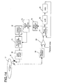
- Figure 14 shows a conventional optical disc drive.
- Light reflected by an optical disc 17 is converted into a reproduction signal by an optical head 18.
- the reproduction signal is shape-rectified by a waveform equalizer 19.
- the resultant reproduction signal is binarized by a comparator 20.
- the threshold of the comparator 20 is feedback-controlled such that an accumulation result of binary signal outputs is 0.
- a phase comparator 21 obtains phase errors between the binary signal outputs and the reproduction clocks.
- the phase errors are averaged by an LPF 22, and a control voltage of a VCO 23 is determined based on the processing result.
- the phase comparator 21 is feedback-controlled such that the phase errors output by the phase comparator 21 are always 0.
- the above-described error detection output is an index for evaluating the recording parameter.
- the recording parameter is set such that the error detection output is as small as possible.
- a recording compensation circuit 27 generates a pulse having a prescribed pattern based on a recording pattern which is output from a pattern generation circuit 26 using an initially set recording parameter.
- a laser driving circuit 28 records information on the optical disc. While information is being reproduced from a track having the prescribed pattern recorded thereon, an error detection circuit 24 accumulates absolute values of phase errors between an output from the comparator 20 and an output from the VCO 23, and thus obtains a detection signal.
- the detection signal is correlated with jitter between a reproduction clock and a binarized pulse edge. Recording and reproduction are repeatedly performed with different recording parameters.
- the recording parameter used when the detection value is minimal is determined as an optimal recording parameter.
- Figure 15 shows a specific operation of the error detection circuit 24.
- a recording pattern having a repetition of 6T, 4T, 6T and 8T is used.
- the mark termination edge corresponding to a pattern of a combination of 4T marks and 6T spaces is optimized. It is assumed that a mark start edge corresponding to a pattern of a combination of 6T spaces and 8T marks, and a mark termination edge corresponding to a pattern of a combination of 8T marks and 6T spaces, are recorded with an optimal recording parameter.
- the recording compensation circuit 27 When given an NRZI signal having a period shown in part (a) of Figure 15, the recording compensation circuit 27 generates a laser waveform pulse shown in part (b) of Figure 15.
- Tsfp is a parameter for setting a mark start position
- Telp is a parameter for setting a mark termination position.
- the laser driving circuit 28 modulates light emitting power in accordance with the pattern shown in part (b) of Figure 15.
- An amorphous area is physically formed on the track as shown in part (c) of Figure 15 by laser light.
- Telp is varied as Telp1, Telp2 and Telp3, the shape of the mark formed is changed as shown in part (c) of Figure 15. Information reproduction from the track having such marks will be discussed.
- a reproduction signal shown with a solid line in part (d) of Figure 15 is obtained.
- the threshold value is defined such that the accumulation value of the outputs from the comparator 20 is 0.
- a phase difference between the output from the comparator 20 and the reproduction clock is detected, and a reproduction clock (part (e) of Figure 15) is generated such that the accumulation value of the phase errors is 0.
- a reproduction signal shown in part (f) of Figure 15 with the solid line is obtained. Since the termination edge of the 4T mark changes in a time axis direction, the threshold value Tv of the comparator 20 is greater than in the reproduction signal shown in part (d) of Figure 15, as indicated by the one-dot chain line in part (f) of Figure 15. Because of the change in the output from the comparator 20, the phase of the reproduction clock is advanced as compared to a reproduction clock shown in part (e) of Figure 15 such that the accumulation value of the phase errors is 0. As a result, a reproduction clock shown in part (g) of Figure 15 is generated.
- a reproduction signal shown in part (h) of Figure 15 with the solid line is obtained. Since the termination edge of the 4T mark changes in a time axis direction, the threshold value Tv of the comparator 20 is smaller than in the reproduction signal shown in part (d) of Figure 15, as indicated by the one-dot chain line in part (h) of Figure 15. Because of the change in the output from the comparator 20, the phase of the reproduction clock is behind as compared to a reproduction clock shown in part (e) of Figure 15 such that the accumulation value of the phase errors is 0. As a result, a reproduction clock shown in part (i) of Figure 15 is generated.
- the time difference distribution between the output from the comparator 20 and the reproduction clock at the mark termination edge (rising edge) is as shown in part (k) of Figure 15.
- the average value of the distributed values at the 4T mark termination edge, and the average value' of the distributed values at the 8T mark termination edge, are each 0.
- the error detection value changes as shown in part (m) of Figure 15 in accordance with the change in the recording parameter Telp. Accordingly, the recording parameter is varied, and the recording parameter when the output from the error detection circuit 24 is minimal is determined as an optimal recording parameter.
- the recording parameter Telp at the 4T mark termination edge is optimized.
- test recordings using a respective specific parameter are performed and the optimal recording parameters are obtained based on the error detection output.
- Figure 16 is a flowshart illustrating an operation for obtaining all the recording parameters in accordance with the above-described procedure.
- Areas of a medium on which test recordings are to be performed are accessed (S161), and the test recordingsare performed while the recording parameter at the mark start edge or the mark termination edge is changed prescribed area by prescribed area (for example, sector by sector) (S163).
- Information is reproduced from the test recording areas, and error deteotion outputs are obtained area by area by which the recording parameter is changed (S164).
- the recording parameter at which the error detection output is minimal is determined as an optimal parameter (S165) . This operation is repeated until all the optimal parameters are obtained (S162) (see Japanese Laid-Open Publications Nos. 2000-200418 and 2001-109597).
- the probability of error generation is not necessarily minimal.
- a signal pattern is estimated from a reproduction signal waveform, and a reproduction signal waveform and the estimated signal waveform are compared with each other, so that the reproduction signal is decoded into a signal having a signal pattern which has the maximum likelihood.
- the probability of error generation is lower as the difference between the reproduction signal waveform and the estimated signal waveform is smaller.
- a recording control apparatus includes a waveform rectification section for receiving a digital signal generated from an analog signal representing information reproduced from an information recording medium, and rectifying a waveform of the digital signal; a maximum likelihood decoding section for performing maximum likelihood decoding of the digital signal having the waveform thereof rectified, and generating a binary signal representing a result of the maximum likelihood decoding; a reliability calculation section for calculating a reliability of the result of the maximum likelihood decoding based on the digital signal having the waveform thereof rectified and the binary signal; and an adjusting section for adjusting a shape of a recording signal for recording the information on the information recording medium based on the calculated reliability.
- the adjusting section adjusts a shape of a prescribed portion of the recording signal.
- the adjusting section adjusts a position of an edge of the recording signal.
- the maximum likelihood decoding section performs maximum likelihood decoding using a state transition rule which is defined by a recording symbol having a minimum polarity inversion interval of 2 and an equalization system PR (C0.C1.C0).
- the maximum likelihood decoding section performs maximum likelihood decoding using a state transition rule which is defined by a recording symbol having a minimum polarity inversion interval of 2 and an equalization system PR (C0,C1,C1,C0).
- the maximum likelihood decoding section performs maximum likelihood decoding using a state transition rule which is defined by a recording symbol having a minimum polarity inversion interval of 2 and an equalization system PR (C0, C1, C2, C1, C0) .
- the reliability calculation section calculates the reliability based on a digital signal corresponding to an end of a recording mark formed on the information recording medium and a binary signal.
- the adjusting section adjusts the shape of the recording signal so as to improve the reliability.
- the adjusting section calculates one of an accumulation value of the calculated reliability and an average value of the calculated reliability, and adjusts the shape of the recording signal based on one of the accumulation value and the average value.
- the adjusting section calculates one of the accumulation value of the calculated reliability and the average value of the calculated reliability for each of combinations of a recording mark length and a space length.
- a recording and reproduction apparatus includes a reproduction section for generating a digital signal from an analog signal representing information reproduced from an information recording medium; a waveform rectification section for receiving the digital signal and rectifying a waveform of the digital signal; a maximum likelihood decoding section for performing maximum likelihood decoding of the digital signal having the waveform thereof rectified, and generating a binary signal representing a result of the maximum likelihood decoding; a reliability calculation section for calculating a reliability of the result of the maximum likelihood decoding based on the digital signal having the waveform thereof rectified and the binary signal; an adjusting section for adjusting a shape of a recording signal for recording the information on the information recording medium based on the calculated reliability; and a recording section for recording the information on the information recording medium based on the adjusting result of the shape of the recording signal.
- a recording control method includes the steps of receiving a digital signal generated from an analog signal representing information reproduced from an information recording medium, and rectifying a waveform of the digital signal; performing maximum likelihood decoding of the digital signal having the waveform thereof rectified, and generating a binary signal representing a result of the maximum likelihood decoding; calculating a reliability of the result of the maximum likelihood decoding based on the digital signal having the waveform thereof rectified and the binary signal; and adjusting a shape of a recording signal for recording the information on the information recording medium based on the calculated reliability.
- the step of adjusting includes the step of adjusting a shape of a prescribed portion of the recording signal.
- the step of adjusting includes the step of adjusting a position of an edge of the recording signal.
- the invention described herein makes possible the advantages of providing a recording control apparatus, a recording and reproduction apparatus, and a recording control method for optimizing a recording parameter when recording information, such that the probability of error generation at the time of maximum likelihood decoding is minimal.
- a method for evaluating the quality of a reproduction signal obtained by using a maximum likelihood decoding method will be described.
- a recording symbol having a minimum polarity inversion interval of 2 is used, and the waveform of the signal is rectified such that the frequency characteristic of the signal at the time of recording and reproduction matches PR (1, 2, 2, 1).
- Level v matching PR (1,2,2,1) is represented by expression 1.
- Level v b k-3 +2b k-2 +2b k-1 +b k where k is an integer representing the time, and v is an integer of 0 through 6.
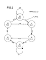
- the state transition table (Table 1) is obtained. State transitions based on a combination of a recording symbol having a minimum polarity inversion interval of 2T and the equalization system of PR (1,2,2,1) State at time k-1 S(b k-3 , b k-2 , b k-1 ) State at time k S ( b k-2 , b k-1 , b k ) B k /Level v S(0, 0, 0) S(0, 0, 0) 0/0 S(0, 0, 0) S(0, 0, 1) 1/1 S(0, 0, 1) S(0, 1, 1) 1/3 S(0, 1, 1) S(1, 1, 0) 0/4 S(0, 1, 1) S(1, 1, 1) 1/5 S(1, 0, 0) S(0, 0, 0) 0/1 S(1, 0, 0) S(0, 0, 1) 1/2 S(
- state (0,0,0) k at time k is S0 k
- state (0,0,1) k at time k is S1 k
- state (0,1,1) k at time k is S2 k
- state (1,1,1) k at time k is S3 k
- state (1, 1, 0) k at time k is S4 k
- state ( 1, 0 , 0 ) k at time k is S5 k
- the state transition diagram shown in Figure 2 represents the state transition rule defined by the minimum polarity inversion interval of 2 and the equalization system of PR ( 1, 2, 2, 1 ) .
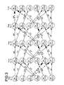
- Figure 3 shows two states transition paths which can be present between state S0 k and state S0 k-4 .
- path A follows states S2 k-4 , S4 k-3 , S5) k-2 , S0 k-1 and S0 k .
- path B follows states S2 k-4 , S3 k-3 , S4 k-2 , S5 k-1 and S0 k .
- the maximum likelihood decoding result from time k-6 to time k is (C k-6 , C k-5 , C k-4 , C k-3 , C k-2 , C k-1 , C k ) .
- path A or path B has the maximum likelihood can be determined by finding an accumulation value of squares of the differences between (i) the value from reproduction signal y k-3 to reproduction signal y k from time k-3 to time k and (ii) the expected value of path A or the expected value of path B.
- the accumulation value of squares of the differences between (i) the value from reproduction signal y k-3 to reproduction signal y k from time k-3 to time k and (ii) the expected value of path A is Pa
- Pa is represented by expression 2.
- Pb is represented by expression 3.
- Pa (y k-3 -4) 2 +(y k-2 -3 ) 2 +(y k-1 -1) 2 + (y k -0 ) 2
- Pb (y k-3 -5) 2 +(y k-2 -5) 2 +(y k-1 -3) 2 +(y k-1 ) 2
- Pa-Pb The difference between Pa and Pb (i. e., Pa-Pb), which represents the reliability of the maximum likelihood decoding result, has the following meaning.
- a maximum likelihood decoding section selects path A with confidence when Pa ⁇ Pb. and selects path B with confidence when Pa»Pb.
- Pa-Pb there is no abnormality found in selecting either path A or path B.
- the probability that the decoding result is correct is 50%.
- Figure 4A shows a distribution of Pa-Pb when noise is superimposed on the reproduction signal.
- the absolute value of Pa-Pb is calculated, and
- Figure 4B shows a distribution of
- the standard deviation ⁇ and the average value Pave of the distribution shown in Figure 4B are obtained.
- the distribution shown in Figure 4B is a normal distribution and, for example, the state where the value of the reliability of decoding result
- the error probability P ( ⁇ , Pave) is represented by expression 4 using ⁇ and Pave.
- the error probability is the probability at which the post-decoding reproduction signal is incorrect.
- P ( ⁇ , Pave) erfc ( Pstd + Pave ⁇ )
- An error probability of the binary signal representing the maximum J likelihood decoding result can be predicted from the average value Pave and the standard deviation ⁇ which are calculated from the distribution of Pa-Pb.
- the average value Pave and the standard deviation ⁇ can be an index of the quality of the reproduction signal.
- is assumed to be a normal distribution. In the case where the distribution is not a normal distribution, the number of times that the value of
- a pattern having a high error probability is a pattern having a small value of reliability Pa-Pb.
- Pa-Pb (A k-3 -B k-3 )+(B k-2 -D k-2 )+(D k-1 -F k-1 )+ (E k -F k ) Pattern-6
- Pa-Pb (B k-3 -C k-3 ) + ( B k-2 -D k-2 ) + (D k-1 -F k-1 ) + (E k -F k )
- Pa-Pb (A k-3 -B
- the above-mentioned 8 patterns are detected for each recording pattern (for each combination of a mark length and a space length immediately before the mark, and for each combination of a mark length and a space length immediately after the mark).
- a recording parameter for optimizing the position of the edge of the recording signal is determined, with specific attention paid to the shape of the recording signal, especially the mark start edge and the mark termination edge. Paying attention only to the pattern having the minimum
- a pattern having a small value of Pa-Pb has a high error probability. This means that by partially optimizing the position of the edge of a recording mark so as to improve the reliability of the maximum likelihood decoding result, the entire recording parameter is optimized.
- a method for optimizing the position of the edge of a recording mark will be described hereinafter.
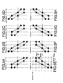
- Figures 5A through 5B show sample values of 8 patterns (Pattern-1 through Pattern-8).
- the horizontal axis represents time.
- One scale represents one channel clock period (Talk ).
- the vertical axis represents signal level (0 through 6).
- the dotted line represents path A, and the solid line represents path B.
- Each sample value corresponds to the expected value Level v 0 through 6 of the maximum likelihood decoding described above with reference to Table 1.
- a recorded portion (amorphous area)is represented as having a signal level below the threshold value of the comparator since the light amount reflected by the recorded portion is lower than the light amount reflected by the other portions.
- An unrecorded portion (non-amorphous area) is represented as having a signal level above the threshold value of the comparator.
- the 8 patterns shown in Figures 5A through 5H each correspond to a reproduction waveform of a border (mark start edge or mark termination edge) between the recorded portion (mark) and an unrecorded portion (space).
- Pattern-1, Pattern-2, Pattern-3, and Pattern-4 each correspond to a mark start edge.
- Pattern-7, and Pattern-8 each correspond to a mark termination edge.
- Pattern-1 A method for detecting a shift of the mark start edge will be described using Pattern-1 as an example.
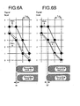
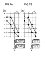
- Figures 6A and 6B show the correlation between the reproduction waveform and the shift of a recording mark of Pattern-1.
- " ⁇ " represents an input signal.
- Path A represented by the dotted line is a correct state transition path.
- the input signal is generated based on a recording mark B1.
- a recording mark A1 has an ideal position of the mark start edge.
- the position of the mark start edge of the recording mark B1 is behind the ideal position.
- the sample value of the input signal (Y k-3 , Y k-2 , Y k-1 , Y k ) is ( 4 . 2 , 3 .2, 1.2, 0.2).
- E1 The absolute value of E1 obtained by expression 9 is the shift amount, and the sign of E1 is the shift direction.
- E1 -2.4. This means that the position of the mark start edge of the recording mark B1 is shifted rearward from the reference by 2.4.
- Figures 7A and 7B show the correlation between the reproduction waveform and the shift of a recording mark of Pattern-1.
- path B represented by the solid line is a correct state transition path.
- " ⁇ " represents an input signal.
- the input signal is generated based on a recording mark B1.
- a recording mark A1 has an ideal position of the mark start edge.
- the position of the mark start edge of the recording mark B1 is behind the ideal position.
- the sample value of the input signal (y k-3 , y k-2 , y k-1 , Y k ) is (5.2, 5.2, 3.2, 1.2).
- E3 is obtained by E3m
- E3 is 2.4.
- the shift direction of the position of the mark start edge of the recording mark can be detected in consideration of this.
- path A is the correct state transition path in Pattern-1
- Pattern-1 is used for detecting the start edge of the recording mark of a combination of a 2T space and a 4T or longer mark.
- path B is the correct state transition path in Pattern-1
- Pattern-1 is used for detecting the start edge of the recordingmark of a combination of a 3T space and a 3T or longer mark.
- the position of the start edge of a recording mark formed on an information recording medium may rely on the length of the space immediately before the recording mark and the length of the recording mark itself. For example, when the length of the space immediately before the recording mark is mT to (m+b)T, the position of the mark start edge of the recording mark relies on the length of the space immediately before the recording mark. When the length of the space immediately before the recording mark is greater than (m+b)T, the position of the mark start edge of the recording mark does not rely on the length of the space immediately before the recording mark.
- the position of the mark start edge of the recording mark relles on the length of the recording mark itself.
- the position of the mark start edge of the recording mark does not rely on the length of the recording mark itself.
- the position of the termination edge of a recording mark formed on an information recording medium may rely on the length of the space immediately after the recording mark and the length of the recording mark itself. For example, when the length of the recording mark itself is mT to (m+a)T, the position of the mark termination edge of the recording mark relies on the length ot the recording mark itself. When the length of the recording mark itself is greater than (m+a)T, the position of the mark termination edge of the recording mark does not rely on the length of the recording mark itself. When the length of the space immediately after the recording mark is mT to (m+b)T, the position of the mark termination edge of the recording mark relies on the length of the space immediately after the recording mark.
- the optimization of the parameter Tsfp at the mark start edge needs to be performed on a recording mark adjacent to a space having a length of (m+b)T or less.
- the optimization of the parameter Telp at the mark termination edge needs to be performed on a recording mark having a length of (m+a)T or less.
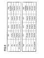
- 2Ts2Tm for example, means a pattern in which a 2T space exists immediately before a 2T mark.
- Figure 9 shows which pattern out of the 8 patterns (Pattern-1 through Pattern-8) is used for detecting the recording patterns (i.e., edge patterns) shown in Figure 8 .
- the shift amount of the signal corresponding to a 2Ts3Tm recording pattern ( Figure 8 ) is detected using P3A Figure 9 ) .
- P3A is Pattern-3 in which path A is the correct state transition path.
- the shift amount of the signal of a 3Ts3Tm recording pattern ( Figure 8 ) is detected using P1B or P4A ( Figure 9 ).
- P1B is a Pattern-1 in which path B is the correct state transition path.
- P4A is a Pattern-4 in which path A is the correct state transition path.
- a method for controlling a recording parameter optimal for the maximum likelihood decoding method is to change the recording parameter such that the shift amount of the signal corresponding to every recording pattern shown in Figure 9 is close to 0.
- the error probability is low; it is not necessary to strictly optimize the recording parameter of these recording patterns. Therefore, an appropriate initial value may be used as the recording parameter instead of optimizing such shift amounts for each information recording medium.
- the 2Ts2Tm recording pattern and the 2Tm2Ts recording pattern may be optimized such that the accumulation value of the phase errors of the reproduction signal is minimal.
- Figure 1 shows a recording and reproduction apparatus 100 according to an example of the present invention.
- the recording and reproduction apparatus 100 executes the above-described method for optimizing recording parameters.
- the recording and reproduction apparatus 100 includes a reproduction section 101, a recording control device 102, and a recording section 103. On the recording and reproduction apparatus 100, an information recording medium 1 can be mounted.
- the information recording medium 1 is usable for optical information recording and reproduction, and is, for example, an optical disc.
- the reproduction section 101 includes an optical head section 2 , a preamplifier 3 , an AGC 4 , a waveform equalizer 5 , an A/D converter 6 , and a PLL circuit 7 .
- the reproduction section 101 generates a digital signal from an analog signal representing information a reproduced from the information recording medium 1.
- the recording control section 102 includes a rectification section 8 , a maximum likelihood decoding section 9 , a reliability calculation section 10 , and an adjusting section 104.
- the adjusting section 104 includes a pattern detection circuit 11 , an edge shift detection circuit 12 , and an information recording medium controller 13 .
- the recording control section 102 is produced as, for example, a semiconductor chip.
- the rectification section 8 is, for example, adigital filter, and receives the digital signal generated by the reproduction section 101 and rectifies the waveform of the digital signal such that the digital signal has a prescribed equalizing characteristic.
- the maximum likelihood decoding section 9 is, for example, a Veterbi decoding circuit, and performs maximum likelihood decoding of the digital signal having the waveform thereof rectified by the rectification section 8 and generates a binary signal representing the result of the maximum likelihood decoding.
- the reliability calculation section 10 is, for example, a differential metric detection circuit, and calculates the reliability of the result of the maximum likelihood decoding based on the digital signal having the waveform thereof rectified by the rectification section 8 and the binary signal output from the maximum likelihood decoding section 9 .
- the reliability calculation section 10 calculates the reliability of the result of the maximum likelihood decoding based on digital signals corresponding to a mark start edge and a mark termination edge of a recording mark formed on the information recording medium 1 and binary signals.
- the adjusting section 104 adjusts the shape of prescribed portions of a recording signal for recording information on the information recording medium 1 based on the reliability calculated by the reliability calculation section 10.
- the adjusting section 104 adjusts, for example, the positions of edges of the recording signal.
- the adjustment of the shape of the recording signal by the adjusting section 104 is performed such that the reliability of the result of the maximum likelihood decoding is improved.
- the information recording medium controller 13 is, for example, an optical disc controller.
- the recording section 103 includes a pattern generation circuit 14 , a recording compensation circuit 15 , a laser driving circuit 16 , and an optical head section 2 .
- the recording section 103 records information on the information recording medium 1 based on the adjusting result of the shape of the recording signal.
- the optical head section 2 is included both in the reproduction section 101 and the recording section 103 , and has both the functions of a recording head and a reproduction head. The recording head and the reproduction head may be separately provided. An operation of the recording and reproduction apparatus 100 will be described in detail below.
- the optical head section 2 generates an analog reproduction signal representing information which is read from the information recording medium 1 .
- the analog reproduction signal is amplified and AC-coupled by the preamplifier 3 and then is input to the AGC 4 .
- the AGC 4 adjusts the gain of the analog reproduction signal such that the output from the waveform equalizer 5 , which will later process the signal, has a constant amplitude.
- the analog reproduction signal which is output from the AGC 4 has the waveform thereof rectified by the waveform equalizer 5 .
- the resultant analog reproduction signal is output to the A/D converter 6 .
- the A/D converter 6 samples the analog reproduction signal in synchronization with a reproduction clock which is output from the PLL circuit 7 .
- the PLL circuit 7 extracts the reproduction clock from a digital reproduction signal obtained by sampling performed by the A/D converter 6 .
- the digital reproduction signal generated by sampling performed by the A/D converter 6 is input to the rectification section 8 .
- the rectification section 8 adjusts the frequency of the digital reproduction signal (i.e., adjusts the waveform of the digital reproduction signal), such that the frequency characteristic of the digital reproduction signal is the characteristic assumed by the maximum likelihood decoding section 9 (in this example, PR (1,2,2,1) equalization characteristic) at the time of recording and reproduction.
- the maximum likelihood decoding section 9 performs maximum likelihood decoding of the digital reproduction signal having the waveform thereof rectified by the rectification section 8 , and thus generates a binary signal.
- the reliability calculation section 10 receives the digital reproduction signal having the waveform thereof rectified by the rectification section 8 and the binary signal.
- the reliability calculation section 10 identifies the state transition from the binary signal, and obtains
- the pattern detection circuit 11 Based on the binary signal, the pattern detection circuit 11 generates a pulse signal for assigning the above-mentioned 8 patterns (Pattern-1 through Pattern- 8 ) for each recording pattern shown in Figure 9 , and outputs the pulse signal to the edge shift detection circuit 12 .
- the edge shift detection circuit 12 accumulatively adds the reliability Pabs pattern by pattern, and obtains a shift of the recording compensation parameter from the optimal value ( i . e . , an edge shift).
- the information recording medium controller 13 changes the recording parameter (waveform of the recording signal) which is determined to be changed based on the edge shift amount added pattern by pattern.
- the pattern generation circuit 14 outputs a recording compensation leaning pattern.
- the recording compensation circuit 15 Based on the recording parameter from the information recording medium controller 13 , the recording compensation circuit 15 generates a laser light emission waveform pattern in accordance with the recording compensation leaning pattern. In accordance with the resultant light emission waveform pattern, the laser driving circuit 16 controls a laser light emission operation of the optical head section 2 .
- Figure 10 shows the pattern detection circuit 11 and the edge shift detection circuit 12.
- the edge shift detection circuit 12 receives a pattern detection result obtained by the pattern detection circuit 11 and the reliability Pabs calculated by the reliability calculation section 10.
- the reliability Pabs data input to the edge shift detection circuit 12 is delayed by a flip-flop (FF) in consideration of the delay caused by the pattern detection circuit 11.
- the reliability Pabs data corresponding to the pattern detection output and the detection output point are input to an adder, and the pattern detection result is input to a selector.
- the selector selects the accumulation result obtained up to that point in accordance with the detection pattern and inputs the selected result to the adder.
- the adder adds the accumulation result and the newly input reliability Pabs data, and outputs the addition result.
- a specific register corresponding to the detection pattern when receiving an enable signal, stores the addition result.
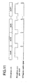
- the flip-flops are reset in a low zone of the addition zone gate signal shown in part (b) of Figure 11 , and the addition result is stored in a high zone.
- the register enable signal shown in part (c) of Figure 11 is generated from the addition zone gate signal.
- the register enable signal is for storing the addition result to registers REG29 through REG0 at the end of the addition zone gate signal.
- Data representing the edge shift amount address by address is stored in the registers REG29 through REG0.
- the edge shift detection circuit 12 owing to such a circuit configuration, can obtain all the edge shift amounts necessary for optimization of the recording parameter using one adder.
- the generation frequency of the recording patterns varies in accordance with the combination of the prescribed length of marks and spaces required for optimization of the recording parameter, among the recording patterns used for test recording (e.g., random patterns).
- the 30 edge shift amounts detected (R23T, R33T, ... R45L, R55L) rely on the generation frequency of the recording patterns.
- the PLL circuit 7 shown in Figure 1 automatically detects a threshold value of a slicer (not shown) using a DC component (a low frequency component included in the reproduction signal) and synchronizes the reproduction signal and the reproduotion clock signal. Accordingly, it is preferable that the amount of the DC component included in the test recording pattern is as small as possible, such that the feedback control does not influence the clock generation performed by the PLL circuit 7 . In consideration of the time required for optimization and precision of optimization, it is preferable to obtain a detection result having a high precision with a minimum possible recording area.
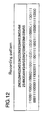
- the following recording pattern is required: a recording pattern which has mark length/space length combinations required for optimization of the recording parameter at the same frequency, in which the code includes no DC component (DSV), and in which the generation frequency, per unit area, of the mark length/space length combinations required for optimization of the recording parameter is high.
- a recording pattern which has mark length/space length combinations required for optimization of the recording parameter at the same frequency, in which the code includes no DC component (DSV), and in which the generation frequency, per unit area, of the mark length/space length combinations required for optimization of the recording parameter is high.
- 2M represents a 2T mark
- 2S represents a 2T space.
- each of 30 patterns of combinations of 2T through 5T marks and 2T through 5T spaces is generated once in a 108-bit recording pattern.
- the number of symbols "0'' and the number of symbols "1" including the 108-bit recording pattern are both 54, and the DSV in the recording pattern is 0.
- each pattern can be detected the same number of times.
- amore accurate shift amount detection result is obtained.
- Figure 13 shows an edge shift detection circuit 12a which is a modification of the edge shift detection circuit 12.
- the edge shift detection circuit 12a random patterns are used for test recording. Namely, different test recording patterns are generated at different frequencies.
- the pattern detection circuit 11 detects an edge of each of specific patterns (30 patterns) shown in Figure 9 .
- the edge shift detection circuit 12a accumulates the edge shift amounts corresponding to each of the patterns, and counts the number of times that each pattern has been detected. By dividing each accumulation result of the edge shift amounts with the number of times that the respective pattern has been detected, the average edge shift amount of each specific pattern is obtained. Thus, even when random patterns are used for test recording, it can be determined which is the pattern corresponding to the recording mark having the mark start edge position or the mark termination edge position which should be changed.
- the edge shift detection circuit 12 included in the adjusting section 104 calculates one of an accumulation value or an average value of the reliability of the maximum likelihood decoding result for each recording pattern ( i. e. , for each mark length/space length combination) , and adjusts the shape of the recording signal based on the accumulation value or average value obtained.
- the state transition rule defined by the recording symbol having a minimum polarity inversion interval of 2 and the equalization system of PR (1, 2, 2, 1) is used by the maximum likelihood decoding section 9 for performing maximum likelihood decoding.
- the present invention is not limited to this.
- the present invention is applicable to use of, for example, a state transition rule defined by the recording symbol having a minimum polarity inversion interval of 3 and the equalization system of PR (C0,C1,C1,C0), a state transition rule defined by the recording symbol having a minimum polarity inversion interval of 2 or 3 and the equalization system of PR (C0, C1, C0) , and a state transition rule defined by the recording symbol having a minimum polarity inversion interval of 2 or 3 and the equalization system of PR (C0, C1, C2, C1, C0).
- C0, C1 and C2 are each an arbitrary positive numeral.
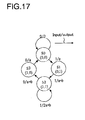
- Table 3 shows the state transition rule defined by the recording symbol having a minimum polarity inversion interval of 2 and an equalization system of PR (a,b,a).
- Figure 17 shows a state transition diagram representing the state transition rule.
- "a” and "b” are each an arbitrary positive numeral.
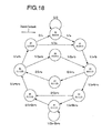
- Table 4 shows the state transition rule defined by the recording symbol having a minimum polarity inversion interval of 2 and an equalization system of PR ( a,b, c, b, a).
- Figure 18 shows a state transition diagram representing the state transition rule.
- "a”, “b” and “c” are each an arbitrary positive numeral.
- the maximum likelihood decoding section 9 may perform maximum likelihood decoding using the state transition rules shown in Tables 3 and 4 and Figures 17 and 18.
- the recording parameter is for controlling the position of the mark start edge and the position of the mark termination edge of a recording mark.
- the present invention is not limited to this.
- a parameter for controlling the width of a leading pulse, the width of a terminating pulse, or the width of a cooling pulse may be adjusted based on the reliability of the maximum likelihood decoding.
- the elements of the recording and reproduction apparatus 100 may be implemented by hardware or software.
- an operation performed by at least one of the rectification section 8 , the maximum likelihood decoding section 9 , the reliability calculation section 10, and the adjusting section 11 may be implemented by a computer-executable program.
- the reliability of the result of the maximum likelihood decoding is calculated based on the digital signal having the waveform thereof rectified and the binary signal generated by the maximum likelihood decoding section. Based on the calculated reliability, the shape of the recording signal for recording information on the information recording medium is adjusted. Thus, the shape of the recording signal can be adjusted so as to improve the reliability of the result of the maximum likelihood decoding, and thus the error probability at the time of maximum likelihood decoding can be reduced.
- a recording parameter which is optimal for the maximum likelihood decoding method is set such that the error probability is minimal when the signal is decoded using the maximum likelihood decoding method.
- the reliability of the result of maximum likelihood decoding is calculated for portions of a signal which correspond to a mark start edge and a mark termination edge of a recording mark and have a high error probability by the maximum likelihood decoding method. This calculation is performed for each of mark length/space length combinations. Based on the calculation result, a recording parameter for optimizing the position of the mark start edge and the position of the mark termination edge is obtained. Information recording is performed reflecting the recording parameter obtained.
- the present invention is especially useful for a recording control apparatus, a recording and reproduction apparatus, and a recording control method using the maximum likelihood decoding method.
Landscapes
- Physics & Mathematics (AREA)
- Signal Processing (AREA)
- Engineering & Computer Science (AREA)
- Nonlinear Science (AREA)
- Mathematical Physics (AREA)
- Crystallography & Structural Chemistry (AREA)
- Chemical & Material Sciences (AREA)
- General Physics & Mathematics (AREA)
- Optics & Photonics (AREA)
- Signal Processing For Digital Recording And Reproducing (AREA)
- Optical Recording Or Reproduction (AREA)
- Optical Head (AREA)
- Error Detection And Correction (AREA)
Applications Claiming Priority (2)
| Application Number | Priority Date | Filing Date | Title |
|---|---|---|---|
| JP2003108821 | 2003-04-14 | ||
| JP2003108821 | 2003-04-14 |
Publications (2)
| Publication Number | Publication Date |
|---|---|
| EP1473723A2 true EP1473723A2 (fr) | 2004-11-03 |
| EP1473723A3 EP1473723A3 (fr) | 2007-10-10 |
Family
ID=32985531
Family Applications (1)
| Application Number | Title | Priority Date | Filing Date |
|---|---|---|---|
| EP04008799A Withdrawn EP1473723A3 (fr) | 2003-04-14 | 2004-04-14 | Appareil de commande d'enregistrement, appareil d'enregistrement et reproduction, et procédé de commande d'enregistrement |
Country Status (5)
| Country | Link |
|---|---|
| US (4) | US7038869B2 (fr) |
| EP (1) | EP1473723A3 (fr) |
| JP (2) | JP4633831B2 (fr) |
| KR (3) | KR101033795B1 (fr) |
| CN (1) | CN1314014C (fr) |
Cited By (2)
| Publication number | Priority date | Publication date | Assignee | Title |
|---|---|---|---|---|
| EP2343702A4 (fr) * | 2008-10-01 | 2013-12-25 | Panasonic Corp | Support d'enregistrement d'information et dispositif d'enregistrement/reproduction |
| EP2346033A4 (fr) * | 2008-10-09 | 2013-12-25 | Panasonic Corp | Procédé d enregistrement optique, dispositif d enregistrement optique, dispositif d exposition d un support matrice, support d enregistrement optique d informations et procédé de reproduction |
Families Citing this family (24)
| Publication number | Priority date | Publication date | Assignee | Title |
|---|---|---|---|---|
| US7038869B2 (en) * | 2003-04-14 | 2006-05-02 | Matsushita Electric Industrial Co., Ltd. | Recording control apparatus, recording and reproduction apparatus, and recording control method |
| JP4154608B2 (ja) * | 2004-05-27 | 2008-09-24 | 日本電気株式会社 | 情報記録媒体への記録方法及び情報記録再生装置並びに情報記録媒体 |
| EP1775722A1 (fr) * | 2004-07-22 | 2007-04-18 | Matsushita Electric Industrial Co., Ltd. | Procede et dispositif de commande d'une impulsion d'enregistrement d'un disque optique et dispositif disque optique utilise a cet effet |
| JP4246246B2 (ja) * | 2005-03-02 | 2009-04-02 | パイオニア株式会社 | 情報再生装置、情報再生方法及び情報再生用プログラム並びに情報記録媒体 |
| WO2006112277A1 (fr) * | 2005-04-14 | 2006-10-26 | Matsushita Electric Industrial Co., Ltd. | Procede d’optimisation du mode d’impulsions d’enregistrement dans l’enregistrement de donnees sur support d’enregistrement d’informations |
| JP4750488B2 (ja) * | 2005-07-08 | 2011-08-17 | ソニー株式会社 | 評価装置、再生装置、評価方法 |
| EP1909280A4 (fr) * | 2005-07-15 | 2009-04-15 | Panasonic Corp | Dispositif d'enregistrement/de reproduction, dispositif d'adaptation des conditions de reproduction et procede d'enregistrement/de reproduction |
| JP4655892B2 (ja) * | 2005-11-07 | 2011-03-23 | ソニー株式会社 | 記録再生装置、記録方法 |
| JP4556912B2 (ja) * | 2006-05-29 | 2010-10-06 | Tdk株式会社 | 光記録媒体の記録条件設定方法 |
| JP5089939B2 (ja) * | 2006-08-11 | 2012-12-05 | ソニーオプティアーク株式会社 | 記録再生装置、評価値演算方法 |
| JP2008159229A (ja) * | 2006-12-26 | 2008-07-10 | Toshiba Corp | 光ディスク記録再生装置、及び光ディスク記録再生方法 |
| EP2043102A4 (fr) * | 2006-12-28 | 2011-07-06 | Panasonic Corp | Procede d'evaluation de support d'enregistrement d'informations, support d'enregistrement d'informations, procede de fabrication de support d'enregistrement d'informations, procede de traitement de signal et dispositif de commande d'acces |
| KR20100115699A (ko) | 2008-02-28 | 2010-10-28 | 파나소닉 주식회사 | 신호 평가 방법 및 신호 평가 장치 |
| JPWO2009122642A1 (ja) * | 2008-03-31 | 2011-07-28 | パナソニック株式会社 | 再生信号品質評価装置及び方法 |
| US20100080095A1 (en) * | 2008-10-01 | 2010-04-01 | Panasonic Corporation | Recording control method, recording/reproduction method, recording control apparatus and recording/reproduction apparatus |
| US8289829B2 (en) * | 2008-10-01 | 2012-10-16 | Panasonic Corporation | Information recording medium and recording/reproduction apparatus |
| US20100085851A1 (en) * | 2008-10-02 | 2010-04-08 | Panasonic Corporation | Method and apparatus for evaluating information recording medium |
| CA2707185A1 (fr) * | 2008-10-02 | 2010-04-08 | Panasonic Corporation | Procede d'evaluation d'un signal reproduit, support d'enregistrement d'0nformations, dispositif de reproduction, et dispositif d'enregistrement |
| US8179760B2 (en) * | 2008-10-02 | 2012-05-15 | Panasonic Corporation | Reproduction signal evaluation method, information recording medium, reproduction apparatus and recording apparatus |
| WO2010067496A1 (fr) * | 2008-12-09 | 2010-06-17 | パナソニック株式会社 | Procédé d'enregistrement optique, dispositif d'enregistrement optique, dispositif d'exposition de support maître, support d'enregistrement d'informations optique et procédé de reproduction |
| US20110164487A1 (en) * | 2009-02-12 | 2011-07-07 | Isao Kobayashi | Information recording/reproducing device and information recording/ reproducing method |
| US8363530B2 (en) | 2010-04-20 | 2013-01-29 | Panasonic Corporation | Information reproduction method, information recording method, and information recording medium |
| KR102618118B1 (ko) | 2023-04-11 | 2023-12-27 | (주)하이세이브아시아 | 냉동시스템의 냉매를 증압 순환시키는 냉매액 펌프의 흡입측에 낮은 온도의 냉매를 공급 순환시키기 위한 액상냉매 순환방법 |
| KR102904079B1 (ko) | 2023-11-20 | 2025-12-24 | (주)하이세이브아시아 | 냉동사이클의 냉매 열교환 순환장치 |
Citations (3)
| Publication number | Priority date | Publication date | Assignee | Title |
|---|---|---|---|---|
| JP2000200418A (ja) | 1998-11-06 | 2000-07-18 | Matsushita Electric Ind Co Ltd | 光ディスクの記録パルス条件を求める方法および装置 |
| JP2001109597A (ja) | 1999-10-07 | 2001-04-20 | Minolta Co Ltd | ネットワークプリンティングシステム |
| US20030067998A1 (en) * | 2001-07-19 | 2003-04-10 | Matsushita Electric Industrial Co., Ltd. | Method for evaluating the quality of read signal and apparatus for reading information |
Family Cites Families (23)
| Publication number | Priority date | Publication date | Assignee | Title |
|---|---|---|---|---|
| US5341249A (en) * | 1992-08-27 | 1994-08-23 | Quantum Corporation | Disk drive using PRML class IV sampling data detection with digital adaptive equalization |
| JPH0877726A (ja) * | 1994-09-06 | 1996-03-22 | Hitachi Ltd | ディジタル信号処理装置、誤り検出方法および記録媒体再生装置 |
| JP3599383B2 (ja) * | 1994-09-20 | 2004-12-08 | 株式会社日立グローバルストレージテクノロジーズ | 磁気記録再生装置及びデータエラーレート測定方法 |
| US5719843A (en) * | 1995-06-22 | 1998-02-17 | Matsushita Electric Industrial Co.Ltd | Method of maximum likelihood decoding and digital information playback apparatus |
| JP3674160B2 (ja) * | 1996-07-04 | 2005-07-20 | ソニー株式会社 | 情報記録再生装置の余裕度検出装置 |
| JP3762831B2 (ja) | 1998-05-08 | 2006-04-05 | 株式会社日立グローバルストレージテクノロジーズ | 情報記録再生回路及びこれを用いた情報記録再生装置 |
| JP3253588B2 (ja) * | 1998-07-06 | 2002-02-04 | 三洋電機株式会社 | 光記録媒体の再生装置、記録装置、および記録再生装置 |
| JP2000156042A (ja) * | 1998-11-18 | 2000-06-06 | Fujitsu Ltd | 信号処理装置及び信号処理方法及び情報記憶装置並びに情報再生装置 |
| US6807134B2 (en) * | 1999-12-28 | 2004-10-19 | Matsushita Electric Industrial Co., Ltd. | Asymmetry detection apparatus, jitter detection apparatus, and recording/reproduction apparatus |
| US6678230B2 (en) * | 2000-10-31 | 2004-01-13 | Matsushita Electric Industrial Co., Ltd. | Waveform equalizer for a reproduction signal obtained by reproducing marks and non-marks recorded on a recording medium |
| JP2002196099A (ja) | 2000-12-25 | 2002-07-10 | Yutaka Arima | α線照射型太陽電池 |
| JP2002230917A (ja) * | 2001-01-30 | 2002-08-16 | Fujitsu Ltd | 磁気記録/再生装置 |
| JPWO2002084653A1 (ja) * | 2001-04-09 | 2004-08-05 | 松下電器産業株式会社 | 記録再生装置 |
| JP4351813B2 (ja) * | 2001-04-20 | 2009-10-28 | 株式会社東芝 | 光ディスク装置 |
| JP2003006864A (ja) * | 2001-06-18 | 2003-01-10 | Toshiba Corp | 光ディスク装置及び光ディスク記録方法 |
| JP2003006865A (ja) * | 2001-06-19 | 2003-01-10 | Sony Corp | 光信号記録装置及びその記録補償方法 |
| JP3926688B2 (ja) * | 2001-07-19 | 2007-06-06 | 松下電器産業株式会社 | 再生信号品質評価方法および情報再生装置 |
| JP3668178B2 (ja) * | 2001-11-09 | 2005-07-06 | 株式会社東芝 | 情報記録再生装置とその信号評価方法及び情報記録再生媒体 |
| JP3697409B2 (ja) * | 2001-11-09 | 2005-09-21 | 株式会社東芝 | 信号品質評価方法および記録補償方法 |
| JP4695814B2 (ja) * | 2002-02-08 | 2011-06-08 | 株式会社日立グローバルストレージテクノロジーズ | データ復号方法・回路及びこれを用いた情報記録再生装置 |
| JP3958084B2 (ja) * | 2002-02-08 | 2007-08-15 | キヤノン株式会社 | 光学的記録再生方法 |
| JP3668202B2 (ja) * | 2002-03-13 | 2005-07-06 | 株式会社東芝 | 情報記録再生装置及びその信号評価方法 |
| US7038869B2 (en) * | 2003-04-14 | 2006-05-02 | Matsushita Electric Industrial Co., Ltd. | Recording control apparatus, recording and reproduction apparatus, and recording control method |
-
2004
- 2004-04-13 US US10/823,264 patent/US7038869B2/en not_active Expired - Lifetime
- 2004-04-14 KR KR1020040025855A patent/KR101033795B1/ko not_active Expired - Lifetime
- 2004-04-14 EP EP04008799A patent/EP1473723A3/fr not_active Withdrawn
- 2004-04-14 CN CNB2004100477977A patent/CN1314014C/zh not_active Expired - Lifetime
-
2005
- 2005-11-17 US US11/283,367 patent/US7417815B2/en not_active Expired - Lifetime
-
2008
- 2008-03-11 US US12/046,025 patent/US7453658B2/en not_active Expired - Lifetime
- 2008-08-07 JP JP2008204692A patent/JP4633831B2/ja not_active Expired - Lifetime
- 2008-10-13 US US12/249,978 patent/US8018810B2/en not_active Expired - Lifetime
-
2009
- 2009-04-14 KR KR1020090032434A patent/KR101033799B1/ko not_active Expired - Lifetime
-
2010
- 2010-08-06 JP JP2010178161A patent/JP4870833B2/ja not_active Expired - Lifetime
- 2010-12-03 KR KR1020100122413A patent/KR101049695B1/ko not_active Expired - Lifetime
Patent Citations (3)
| Publication number | Priority date | Publication date | Assignee | Title |
|---|---|---|---|---|
| JP2000200418A (ja) | 1998-11-06 | 2000-07-18 | Matsushita Electric Ind Co Ltd | 光ディスクの記録パルス条件を求める方法および装置 |
| JP2001109597A (ja) | 1999-10-07 | 2001-04-20 | Minolta Co Ltd | ネットワークプリンティングシステム |
| US20030067998A1 (en) * | 2001-07-19 | 2003-04-10 | Matsushita Electric Industrial Co., Ltd. | Method for evaluating the quality of read signal and apparatus for reading information |
Non-Patent Citations (1)
| Title |
|---|
| AKIHITO OGAWA; YUJI NAGAI; KAZUO WATABE; KATSUO IWATA; SUMITAKA MARUYAMA; MAKOTO NAGASATO; YUTAKA KASHIHARA: "New Write Shift Compensation Method Modified for Optical Disk Systems to Which Partial Response Maximum Likelihood (PRML) Detection Is Applied", JPN. J. APPL. PHYS., vol. 42, no. 2B, 28 February 2003 (2003-02-28), pages 919 - 923, XP002447359, DOI: doi:10.1143/JJAP.42.919 |
Cited By (2)
| Publication number | Priority date | Publication date | Assignee | Title |
|---|---|---|---|---|
| EP2343702A4 (fr) * | 2008-10-01 | 2013-12-25 | Panasonic Corp | Support d'enregistrement d'information et dispositif d'enregistrement/reproduction |
| EP2346033A4 (fr) * | 2008-10-09 | 2013-12-25 | Panasonic Corp | Procédé d enregistrement optique, dispositif d enregistrement optique, dispositif d exposition d un support matrice, support d enregistrement optique d informations et procédé de reproduction |
Also Published As
| Publication number | Publication date |
|---|---|
| US20060067189A1 (en) | 2006-03-30 |
| KR20040088988A (ko) | 2004-10-20 |
| US7038869B2 (en) | 2006-05-02 |
| JP4633831B2 (ja) | 2011-02-16 |
| JP2010272206A (ja) | 2010-12-02 |
| EP1473723A3 (fr) | 2007-10-10 |
| US20080165651A1 (en) | 2008-07-10 |
| CN1314014C (zh) | 2007-05-02 |
| KR101033795B1 (ko) | 2011-05-13 |
| US7417815B2 (en) | 2008-08-26 |
| US20090103412A1 (en) | 2009-04-23 |
| US7453658B2 (en) | 2008-11-18 |
| KR20100134542A (ko) | 2010-12-23 |
| CN1591604A (zh) | 2005-03-09 |
| US8018810B2 (en) | 2011-09-13 |
| JP4870833B2 (ja) | 2012-02-08 |
| JP2008293651A (ja) | 2008-12-04 |
| KR101049695B1 (ko) | 2011-07-19 |
| KR101033799B1 (ko) | 2011-05-13 |
| KR20090045180A (ko) | 2009-05-07 |
| US20050078579A1 (en) | 2005-04-14 |
Similar Documents
| Publication | Publication Date | Title |
|---|---|---|
| US8018810B2 (en) | Recording control apparatus, recording and reproduction apparatus, and recording control method | |
| US7907487B2 (en) | Recording/reproduction apparatus, recording/reproduction method, program, and recording power adjustment apparatus | |
| US7082566B2 (en) | Signal quality evaluation method, information recording/reproducing system, and recording compensation method | |
| US7095696B2 (en) | Recording/reproducing device | |
| JP2004335079A (ja) | 記録制御装置、記録再生装置および記録制御方法 | |
| US7349321B2 (en) | Information reproduction apparatus and information reproduction method | |
| JP2002175673A (ja) | Pll回路、データ検出回路及びディスク装置 | |
| JP2003141823A (ja) | 再生信号品質評価方法および情報再生装置 | |
| US8000197B2 (en) | Recording/reproducing device, recording condition adjusting device and recording/reproducing method | |
| US20040246864A1 (en) | Apparatus and method for controlling recording or reproduction, apparatus for performing recording or reproduction, and information recording medium identification apparatus | |
| KR100562452B1 (ko) | 광 디스크 장치 및 위상 조정 방법 | |
| JP4350024B2 (ja) | 記録パワー制御方法、記録方法、記録パワー制御装置、記録装置、及びパワー制御プログラム | |
| US20090168622A1 (en) | Optical disk apparatus | |
| JP2002319231A (ja) | 光学的情報記録再生装置 | |
| JP2001023304A (ja) | 記録補償装置 | |
| JP2006344339A (ja) | 光記録媒体記録再生装置及びその記録パラメータ補正方法 |
Legal Events
| Date | Code | Title | Description |
|---|---|---|---|
| PUAI | Public reference made under article 153(3) epc to a published international application that has entered the european phase |
Free format text: ORIGINAL CODE: 0009012 |
|
| AK | Designated contracting states |
Kind code of ref document: A2 Designated state(s): AT BE BG CH CY CZ DE DK EE ES FI FR GB GR HU IE IT LI LU MC NL PL PT RO SE SI SK TR |
|
| AX | Request for extension of the european patent |
Extension state: AL HR LT LV MK |
|
| PUAL | Search report despatched |
Free format text: ORIGINAL CODE: 0009013 |
|
| AK | Designated contracting states |
Kind code of ref document: A3 Designated state(s): AT BE BG CH CY CZ DE DK EE ES FI FR GB GR HU IE IT LI LU MC NL PL PT RO SE SI SK TR |
|
| AX | Request for extension of the european patent |
Extension state: AL HR LT LV MK |
|
| 17P | Request for examination filed |
Effective date: 20080409 |
|
| AKX | Designation fees paid |
Designated state(s): CZ DE FR GB |
|
| 17Q | First examination report despatched |
Effective date: 20080819 |
|
| RAP1 | Party data changed (applicant data changed or rights of an application transferred) |
Owner name: PANASONIC CORPORATION |
|
| STAA | Information on the status of an ep patent application or granted ep patent |
Free format text: STATUS: THE APPLICATION HAS BEEN WITHDRAWN |
|
| 18W | Application withdrawn |
Effective date: 20110829 |