EP1473793A2 - Membranelektrodeneinheiten - Google Patents
Membranelektrodeneinheiten Download PDFInfo
- Publication number
- EP1473793A2 EP1473793A2 EP04251562A EP04251562A EP1473793A2 EP 1473793 A2 EP1473793 A2 EP 1473793A2 EP 04251562 A EP04251562 A EP 04251562A EP 04251562 A EP04251562 A EP 04251562A EP 1473793 A2 EP1473793 A2 EP 1473793A2
- Authority
- EP
- European Patent Office
- Prior art keywords
- film
- membrane electrode
- proton exchange
- repeating
- unit cells
- Prior art date
- Legal status (The legal status is an assumption and is not a legal conclusion. Google has not performed a legal analysis and makes no representation as to the accuracy of the status listed.)
- Granted
Links
Images



Classifications
-
- H—ELECTRICITY
- H01—ELECTRIC ELEMENTS
- H01M—PROCESSES OR MEANS, e.g. BATTERIES, FOR THE DIRECT CONVERSION OF CHEMICAL ENERGY INTO ELECTRICAL ENERGY
- H01M4/00—Electrodes
- H01M4/86—Inert electrodes with catalytic activity, e.g. for fuel cells
- H01M4/88—Processes of manufacture
- H01M4/8803—Supports for the deposition of the catalytic active composition
- H01M4/881—Electrolytic membranes
-
- H—ELECTRICITY
- H01—ELECTRIC ELEMENTS
- H01M—PROCESSES OR MEANS, e.g. BATTERIES, FOR THE DIRECT CONVERSION OF CHEMICAL ENERGY INTO ELECTRICAL ENERGY
- H01M4/00—Electrodes
- H01M4/02—Electrodes composed of, or comprising, active material
- H01M4/04—Processes of manufacture in general
- H01M4/043—Processes of manufacture in general involving compressing or compaction
- H01M4/0435—Rolling or calendering
-
- H—ELECTRICITY
- H01—ELECTRIC ELEMENTS
- H01M—PROCESSES OR MEANS, e.g. BATTERIES, FOR THE DIRECT CONVERSION OF CHEMICAL ENERGY INTO ELECTRICAL ENERGY
- H01M4/00—Electrodes
- H01M4/02—Electrodes composed of, or comprising, active material
- H01M4/64—Carriers or collectors
- H01M4/66—Selection of materials
-
- H—ELECTRICITY
- H01—ELECTRIC ELEMENTS
- H01M—PROCESSES OR MEANS, e.g. BATTERIES, FOR THE DIRECT CONVERSION OF CHEMICAL ENERGY INTO ELECTRICAL ENERGY
- H01M4/00—Electrodes
- H01M4/02—Electrodes composed of, or comprising, active material
- H01M4/64—Carriers or collectors
- H01M4/66—Selection of materials
- H01M4/661—Metal or alloys, e.g. alloy coatings
-
- H—ELECTRICITY
- H01—ELECTRIC ELEMENTS
- H01M—PROCESSES OR MEANS, e.g. BATTERIES, FOR THE DIRECT CONVERSION OF CHEMICAL ENERGY INTO ELECTRICAL ENERGY
- H01M4/00—Electrodes
- H01M4/02—Electrodes composed of, or comprising, active material
- H01M4/64—Carriers or collectors
- H01M4/66—Selection of materials
- H01M4/663—Selection of materials containing carbon or carbonaceous materials as conductive part, e.g. graphite, carbon fibres
-
- H—ELECTRICITY
- H01—ELECTRIC ELEMENTS
- H01M—PROCESSES OR MEANS, e.g. BATTERIES, FOR THE DIRECT CONVERSION OF CHEMICAL ENERGY INTO ELECTRICAL ENERGY
- H01M8/00—Fuel cells; Manufacture thereof
- H01M8/10—Fuel cells with solid electrolytes
- H01M8/1004—Fuel cells with solid electrolytes characterised by membrane-electrode assemblies [MEA]
-
- H—ELECTRICITY
- H01—ELECTRIC ELEMENTS
- H01M—PROCESSES OR MEANS, e.g. BATTERIES, FOR THE DIRECT CONVERSION OF CHEMICAL ENERGY INTO ELECTRICAL ENERGY
- H01M8/00—Fuel cells; Manufacture thereof
- H01M8/10—Fuel cells with solid electrolytes
- H01M8/1016—Fuel cells with solid electrolytes characterised by the electrolyte material
- H01M8/1018—Polymeric electrolyte materials
- H01M8/102—Polymeric electrolyte materials characterised by the chemical structure of the main chain of the ion-conducting polymer
- H01M8/1023—Polymeric electrolyte materials characterised by the chemical structure of the main chain of the ion-conducting polymer having only carbon, e.g. polyarylenes, polystyrenes or polybutadiene-styrenes
-
- H—ELECTRICITY
- H01—ELECTRIC ELEMENTS
- H01M—PROCESSES OR MEANS, e.g. BATTERIES, FOR THE DIRECT CONVERSION OF CHEMICAL ENERGY INTO ELECTRICAL ENERGY
- H01M8/00—Fuel cells; Manufacture thereof
- H01M8/10—Fuel cells with solid electrolytes
- H01M8/1016—Fuel cells with solid electrolytes characterised by the electrolyte material
- H01M8/1018—Polymeric electrolyte materials
- H01M8/1039—Polymeric electrolyte materials halogenated, e.g. sulfonated polyvinylidene fluorides
-
- H—ELECTRICITY
- H01—ELECTRIC ELEMENTS
- H01M—PROCESSES OR MEANS, e.g. BATTERIES, FOR THE DIRECT CONVERSION OF CHEMICAL ENERGY INTO ELECTRICAL ENERGY
- H01M8/00—Fuel cells; Manufacture thereof
- H01M8/24—Grouping of fuel cells, e.g. stacking of fuel cells
- H01M8/2404—Processes or apparatus for grouping fuel cells
-
- H—ELECTRICITY
- H01—ELECTRIC ELEMENTS
- H01M—PROCESSES OR MEANS, e.g. BATTERIES, FOR THE DIRECT CONVERSION OF CHEMICAL ENERGY INTO ELECTRICAL ENERGY
- H01M8/00—Fuel cells; Manufacture thereof
- H01M8/24—Grouping of fuel cells, e.g. stacking of fuel cells
- H01M8/241—Grouping of fuel cells, e.g. stacking of fuel cells with solid or matrix-supported electrolytes
-
- H—ELECTRICITY
- H01—ELECTRIC ELEMENTS
- H01M—PROCESSES OR MEANS, e.g. BATTERIES, FOR THE DIRECT CONVERSION OF CHEMICAL ENERGY INTO ELECTRICAL ENERGY
- H01M4/00—Electrodes
- H01M4/02—Electrodes composed of, or comprising, active material
- H01M4/64—Carriers or collectors
- H01M4/70—Carriers or collectors characterised by shape or form
-
- H—ELECTRICITY
- H01—ELECTRIC ELEMENTS
- H01M—PROCESSES OR MEANS, e.g. BATTERIES, FOR THE DIRECT CONVERSION OF CHEMICAL ENERGY INTO ELECTRICAL ENERGY
- H01M4/00—Electrodes
- H01M4/86—Inert electrodes with catalytic activity, e.g. for fuel cells
- H01M4/90—Selection of catalytic material
- H01M4/92—Metals of platinum group
-
- Y—GENERAL TAGGING OF NEW TECHNOLOGICAL DEVELOPMENTS; GENERAL TAGGING OF CROSS-SECTIONAL TECHNOLOGIES SPANNING OVER SEVERAL SECTIONS OF THE IPC; TECHNICAL SUBJECTS COVERED BY FORMER USPC CROSS-REFERENCE ART COLLECTIONS [XRACs] AND DIGESTS
- Y02—TECHNOLOGIES OR APPLICATIONS FOR MITIGATION OR ADAPTATION AGAINST CLIMATE CHANGE
- Y02E—REDUCTION OF GREENHOUSE GAS [GHG] EMISSIONS, RELATED TO ENERGY GENERATION, TRANSMISSION OR DISTRIBUTION
- Y02E60/00—Enabling technologies; Technologies with a potential or indirect contribution to GHG emissions mitigation
- Y02E60/10—Energy storage using batteries
-
- Y—GENERAL TAGGING OF NEW TECHNOLOGICAL DEVELOPMENTS; GENERAL TAGGING OF CROSS-SECTIONAL TECHNOLOGIES SPANNING OVER SEVERAL SECTIONS OF THE IPC; TECHNICAL SUBJECTS COVERED BY FORMER USPC CROSS-REFERENCE ART COLLECTIONS [XRACs] AND DIGESTS
- Y02—TECHNOLOGIES OR APPLICATIONS FOR MITIGATION OR ADAPTATION AGAINST CLIMATE CHANGE
- Y02E—REDUCTION OF GREENHOUSE GAS [GHG] EMISSIONS, RELATED TO ENERGY GENERATION, TRANSMISSION OR DISTRIBUTION
- Y02E60/00—Enabling technologies; Technologies with a potential or indirect contribution to GHG emissions mitigation
- Y02E60/30—Hydrogen technology
- Y02E60/50—Fuel cells
-
- Y—GENERAL TAGGING OF NEW TECHNOLOGICAL DEVELOPMENTS; GENERAL TAGGING OF CROSS-SECTIONAL TECHNOLOGIES SPANNING OVER SEVERAL SECTIONS OF THE IPC; TECHNICAL SUBJECTS COVERED BY FORMER USPC CROSS-REFERENCE ART COLLECTIONS [XRACs] AND DIGESTS
- Y02—TECHNOLOGIES OR APPLICATIONS FOR MITIGATION OR ADAPTATION AGAINST CLIMATE CHANGE
- Y02P—CLIMATE CHANGE MITIGATION TECHNOLOGIES IN THE PRODUCTION OR PROCESSING OF GOODS
- Y02P70/00—Climate change mitigation technologies in the production process for final industrial or consumer products
- Y02P70/50—Manufacturing or production processes characterised by the final manufactured product
Definitions
- Membrane electrode assemblies are the core of fuel cells such as proton exchange media fuel cells which are well known. See, for example, “Fuel Cell Systems Explained,” Larminie & Dicks, John Wylie & Sons, Ltd. (2000), the contents of which are incorporated herein by reference. Membrane electrode assemblies contain the electron collectors, the catalyst, and the proton exchange medium. Current methods of production of MEAs focus on individual units in which the catalysts are chemically deposited or inked on an electron collector and proton exchange medium. The elements of the unit are then sandwiched together with the application of heat and pressure to produce a single MEA. This prior art method is both costly and not easily scaled up to high volume production.
- the invention is a method for making a membrane electrode assembly including providing an elongate proton exchange membrane film having a front and a back side.
- a first catalyst material is deposited in a repeating cell pattern on the front side of the film to form cathode regions of a plurality of unit cells.
- a second catalyst material is deposited in the repeating pattern on the back side of the film to form anode regions of the unit cells.
- An elongate support film perforated in the repeating cell pattern is provided and electron conductor material is deposited onto the support film in the repeating cell pattern along with electrical contact nubs.
- An adhesive film precut in the repeating cell pattern is also provided and the support and adhesive films are assembled on the front and back sides of the proton exchange membrane film with the repeating patterns of the respective films aligned and with the unit cells connected electrically.
- the assembled films are passed through hot rollers to laminate the films to produce the assembly.
- the method for making a membrane electrode assembly includes providing an elongate proton exchange membrane film having a front and back side.
- a first catalyst material is deposited in a repeating cell pattern on the front side of the film to form cathode regions of a plurality of unit cells.
- a second catalyst material is deposited in the repeating pattern on the back side of the film to form anode regions of the unit cells.
- An elongate support film perforated in the repeating cell pattern is provided and electron conductor material is deposited onto the support film in the repeating cell pattern along with electrical contact nubs.
- An adhesive film pre-cut in the repeating cell pattern is also provided and the support and adhesive films are assembled on the front and back sides of the proton exchange membrane film with the repeating patterns of the respective films aligned and with the unit cells connected electrically.
- a suitable proton exchange membrane film is Nafion R available from Dupont Chemical Corporation. Nafion is basically sulphonated polytetrafluoroethylene.
- a suitable first catalyst material is platinum and a suitable second catalyst material is platinum-ruthenium.
- a suitable support film is Kapton.
- Suitable electronic conductor materials are thin film carbon and thin film metals.
- the unit cells made according to the present invention may be connected electrically in series or in parallel.
- the proton exchange membrane, the support film, and the adhesive film be fed from respective rolls and that the completed membrane electrode assembly is in the form of a continuous roll of material.
- the invention is a fuel cell including a Z-folded strip including a plurality of electrically connected membrane electrode assemblies as described above.
- a pair of endplates support the Z-folded strip to create alternating anode and cathode chambers. Alternating fuel and air manifolds are provided in the endplates to complete a fuel cell.
- the present invention thus produces membrane electrode assemblies in a reel-to-reel process.
- the method according to the invention allows MEAs to be constructed in a continuous process wherein each cell is connected electrically to the next either in series or in parallel as desired. With a series connection the desired voltage is proportional to the number of cells so that one simply chooses the appropriate number of cells and cuts them from the reel to form them into a stack. Alternatively, stacks themselves may be connected in series or parallel.
- the continuous production process of the invention is low cost and scalable to very high volume.
- the cells are internally connected, in series or in parallel, and any desired voltage may be selected by using the appropriate number of cells.
- a proton exchange membrane (PEM) film 10 is a polymer electrolyte membrane.
- a suitable membrane is a sulphonated fluoropolymer, often fluoroethylene, such as Nafion, a registered trademark of, and available from, the Dupont Chemical Corporation.
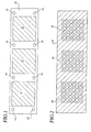
- a catalyst 12 is deposited in a repeating pattern on a front surface of the PEM film membrane 10.
- a catalyst is also deposited on the back surface of the film 10.
- Contact vias 14 are punched out of the membrane 10.
- a suitable catalyst 12 is platinum to form a cathode region and a suitable catalyst for the other side of the PEM 10 is platinum-ruthenium to form an anode region.
- the catalysts are deposited by any suitable technique known to those skilled in the art.
- the catalyst pattern will define unit cells in a completed membrane electrode assembly as will become clear in this specification.
- a support film 16 is preferably made of Kapton or other type of polyimide material or other suitable plastic material.
- the Kapton film 16 includes perforations 18 in the same repeating pattern as with the catalyst 12 shown in Fig. 1. The perforations 18 will allow fuel and air to reach the catalysts once the membrane electrode assembly is assembled. It is preferred that the Kapton film 16 be provided on and deployed from a roll.
- electron conductor material 20 and an optional catalyst is deposited on the Kapton film 16.
- a suitable electron conductor material 20 is carbon or thin film metal such as stainless steel. If desired, an optional catalyst may be deposited on top of the electron conductor material.
- the electron conductor and optional catalyst depositions can be achieved by sputtering through a shadow mask, for example.
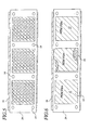
- contact nubs 22 are located either on the right or left of the cell pattern depending on whether the Kapton film 16 is laminated on the front or back of the PEM film.
- the contact nubs 22 will eventually be in electrical contact, as will be described below.
- the nubs 22 will thereby form a continuous series electrical connection between cells along the completed membrane electrode assembly on a reel.
- an adhesive film 24 is pre-cut to expose the electron conductor/catalyst on the Kapton film 16 as well as the contact vias 14.
- a suitable temperature/pressure sensitive adhesive film 24 is based on epoxy, urethane, silicone or acrylate adhesive chemistry.
- the adhesive material 24 is in its low-tack form as it is aligned over the Kapton film 16 and laminated to it.
- the adhesive film 24 will be heat cured later in the process as described below.
- the PEM film 10 is aligned over the adhesive film 24 /Kapton film 16 combination so that the catalyst area 12 is aligned with the perforations 20.
- a second adhesive film is also aligned.
- a second processed Kapton film described in Figs. 3 and 4 is aligned and laminated over the adhesive film 24 .
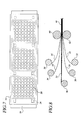
- Fig. 8 Schematically, Kapton support film 16 is supported on rolls 30 and 32 . Similarly, the adhesive film 24 is supported on rolls 34 and 36. Finally, the PEM film 10 is supported on a roll 38. As discussed above, these various layers are aligned and registered and passed through the nip of hot rollers 40 and 42 to produce the completed membrane electrode assembly 44 and as shown in Fig. 7. It will be appreciated that the individual cells are connected in series electrically. The completed membrane electrode assembly 44 may be wound onto a takeup roll (not shown).
- Fig. 9 illustrates a 5-cell strip of the completed MEA Z-folded to form alternating anode 46 and cathode 48 chambers. Electrical anode contacts are made at 50 and external cathode contacts are made at area 52 beneath the lower anode chamber 46 .
- the cells in the Z-folded MEA of Fig. 9 are connected in series so that individual cell voltages are additive.
- the Z-folded strip is mated to an end plate 52.
- the MEA assembly 44 is bonded into a groove in the end plate 52.
- Alternating fuel manifolds 54 and air manifolds 56 are molded into the end plate 52 which may be made of plastic. In this way, fuel is brought into contact with the anode and air is brought into contact with the cathode of each of the cells in the unit.
- additional cover plates in addition to the two end plates complete the fuel cell stack.
- Fig. 12 An alternative process referred to as a roll transfer lamination process is shown in Fig. 12.
- the adhesive film 24 is pre-cut around each cell as with the earlier embodiment.
- the PEM material 10 is also pre-cut into squares designed to fit exactly into a cell opening left by the adhesive film 24.
- the pre-cut PEM material 10 is carried by a backing film 60 that passes over a transfer roll 62 and is discarded on a take up roll 64 .
- the pre-cut PEM material 10 is transferred to the Kapton support film 16 at the location of a compression roller 66 and inserted into the opening left by the adhesive film 24.
- the thickness of the adhesive film 24 is adjusted to accommodate the thickness of the PEM material 10 . Note that in this embodiment, only one adhesive film is required. As with the earlier embodiment, the material passes through the nip of hot rollers 40 and 42.
- the process illustrated in Fig. 12 has several advantages. First of all it uses less of the expensive PEM material. Second, the process eliminates one adhesive film but requires the one used to be not only thicker but also to have a specified thickness. Finally, the adhesive film is not required to bond to the PEM material as in the earlier embodiment.
- Fig. 12 The roll transfer lamination process of Fig. 12 will be used to illustrate a parallel electrical connection of the individual cells.
- Fig. 13 is similar to the embodiment of Fig. 1 but note that there are no vias for parallel electrical connection.
- adjacent cells are connected to each other unlike the embodiment of Fig. 4.
- Fig 14 all anodes are connected together and all cathodes are connected together resulting in a parallel electrical connection.
- Kapton film with appropriate thin film is required for either anode or cathode use as shown in Fig. 14.
- This parallel type of connection has the great advantage of not requiring internal connection which can complicate the process.
- the completed parallel connect PEM material is shown in Figs. 15 and 16.
- Figs.17 and 18 illustrate a conventional flooded anode stack design.
- each cell is cut from the roll, bonded to gasket material 70 and built into a stack as shown in Fig. 18.
- This design has the advantage of simplicity but the disadvantage that all electrical connections must be done externally as shown at 72 in Fig 18.
- Fig. 19 the stack is similar to that shown in Fig. 18 except that an anode wicking medium 72 is included in each anode chamber.
- the stack design of Fig. 19 uses the capillary material 72 to bring fuel to the anode chamber. This design provides numerous advantages that are described in the copending and commonly owned Patent Application Serial Number 10/251,244, the contents of which are incorporated herein by reference.
Landscapes
- Chemical & Material Sciences (AREA)
- Chemical Kinetics & Catalysis (AREA)
- Engineering & Computer Science (AREA)
- General Chemical & Material Sciences (AREA)
- Electrochemistry (AREA)
- Manufacturing & Machinery (AREA)
- Sustainable Development (AREA)
- Sustainable Energy (AREA)
- Life Sciences & Earth Sciences (AREA)
- Materials Engineering (AREA)
- Crystallography & Structural Chemistry (AREA)
- Fuel Cell (AREA)
- Inert Electrodes (AREA)
- Electrolytic Production Of Non-Metals, Compounds, Apparatuses Therefor (AREA)
Applications Claiming Priority (2)
| Application Number | Priority Date | Filing Date | Title |
|---|---|---|---|
| US428171 | 2003-04-30 | ||
| US10/428,171 US7049024B2 (en) | 2003-04-30 | 2003-04-30 | Membrane electrode assemblies and method for manufacture |
Publications (3)
| Publication Number | Publication Date |
|---|---|
| EP1473793A2 true EP1473793A2 (de) | 2004-11-03 |
| EP1473793A3 EP1473793A3 (de) | 2006-07-19 |
| EP1473793B1 EP1473793B1 (de) | 2009-07-08 |
Family
ID=32990467
Family Applications (1)
| Application Number | Title | Priority Date | Filing Date |
|---|---|---|---|
| EP04251562A Expired - Lifetime EP1473793B1 (de) | 2003-04-30 | 2004-03-18 | Membranelektrodeneinheiten |
Country Status (5)
| Country | Link |
|---|---|
| US (2) | US7049024B2 (de) |
| EP (1) | EP1473793B1 (de) |
| JP (1) | JP4032042B2 (de) |
| DE (1) | DE602004021871D1 (de) |
| TW (1) | TW200423464A (de) |
Cited By (6)
| Publication number | Priority date | Publication date | Assignee | Title |
|---|---|---|---|---|
| WO2004107483A3 (en) * | 2003-05-28 | 2005-09-15 | 3M Innovative Properties Co | Roll-good fuel cell fabrication processes, equipment, and articles produced from same |
| US7018500B2 (en) | 2002-04-03 | 2006-03-28 | 3M Innovative Properties Company | Apparatus and method for singulating porous fuel cell layers using adhesive tape pick head |
| US7022207B2 (en) | 2002-04-03 | 2006-04-04 | 3M Innovative Properties Company | Method and apparatus for peeling a thin film from a liner |
| US7432009B2 (en) | 2002-04-03 | 2008-10-07 | 3M Innovative Properties Company | Lamination apparatus and methods |
| US7569081B2 (en) | 2002-04-03 | 2009-08-04 | 3M Innovative Properties Company | Method for converting a fuel cell membrane web to precisely positioned membrane sheets |
| WO2011039523A1 (en) * | 2009-09-30 | 2011-04-07 | Afc Energy Plc | Cell stack |
Families Citing this family (34)
| Publication number | Priority date | Publication date | Assignee | Title |
|---|---|---|---|---|
| JP4249960B2 (ja) * | 2002-08-28 | 2009-04-08 | 新光電気工業株式会社 | 燃料電池セル |
| EP1492184A1 (de) * | 2003-06-27 | 2004-12-29 | Umicore AG & Co. KG | Verfahren zur Herstellung einer katalysatorbeschichteten Polymerelektrolyt-Membran |
| US20050095490A1 (en) * | 2003-10-31 | 2005-05-05 | Mittelstadt Laurie S. | Fuel cell assembly gasket for fuel containment |
| US8153285B2 (en) * | 2003-12-29 | 2012-04-10 | Honeywell International Inc. | Micro fuel cell |
| US7879472B2 (en) * | 2003-12-29 | 2011-02-01 | Honeywell International Inc. | Micro fuel cell |
| US9029028B2 (en) | 2003-12-29 | 2015-05-12 | Honeywell International Inc. | Hydrogen and electrical power generator |
| JP2005347256A (ja) * | 2004-05-28 | 2005-12-15 | Ei Du Pont Canada Co | 電気化学的電池構成要素用の新規な密封剤 |
| JP2006344586A (ja) * | 2005-05-13 | 2006-12-21 | Hitachi Cable Ltd | 燃料電池 |
| US20080261095A1 (en) * | 2005-06-20 | 2008-10-23 | Masaki Yamauchi | Membrane-Electrode Assembly, Method for Manufacturing the Same, and Fuel Cell |
| ITMI20052508A1 (it) * | 2005-12-28 | 2007-06-29 | Solvay Solexis Spa | Processo per ottenere ccm con subgasket |
| US7713653B2 (en) * | 2006-10-06 | 2010-05-11 | Honeywell International Inc. | Power generation capacity indicator |
| US8822097B2 (en) | 2006-11-30 | 2014-09-02 | Honeywell International Inc. | Slide valve for fuel cell power generator |
| US8012284B2 (en) * | 2006-12-15 | 2011-09-06 | 3M Innovative Properties Company | Method and apparatus for fabricating roll good fuel cell subassemblies |
| US8288059B2 (en) * | 2006-12-15 | 2012-10-16 | 3M Innovative Properties Company | Processing methods and systems for assembling fuel cell perimeter gaskets |
| WO2009017147A1 (ja) * | 2007-08-02 | 2009-02-05 | Sharp Kabushiki Kaisha | 燃料電池スタックおよび燃料電池システム |
| US8993135B2 (en) * | 2007-11-01 | 2015-03-31 | Honeywell International Inc. | Fuel cell stack for hydrogen fuel power generator |
| US9029038B2 (en) | 2007-11-01 | 2015-05-12 | Honeywell International Inc. | Method of forming a fuel cell stack |
| US7892692B2 (en) * | 2008-01-10 | 2011-02-22 | GM Global Technology Operations LLC | Features for barrier film support |
| US9276285B2 (en) | 2008-12-15 | 2016-03-01 | Honeywell International Inc. | Shaped fuel source and fuel cell |
| US8932780B2 (en) | 2008-12-15 | 2015-01-13 | Honeywell International Inc. | Fuel cell |
| US8962211B2 (en) | 2008-12-15 | 2015-02-24 | Honeywell International Inc. | Rechargeable fuel cell |
| WO2010114059A1 (ja) * | 2009-04-01 | 2010-10-07 | シャープ株式会社 | 燃料電池スタックおよびこれを備える電子機器 |
| US20110000864A1 (en) * | 2009-07-06 | 2011-01-06 | Moore Lela K | Cookware Holder and Method |
| GB2475334B (en) | 2009-11-17 | 2016-02-03 | Intelligent Energy Ltd | Plate processing |
| US8246796B2 (en) | 2010-02-12 | 2012-08-21 | Honeywell International Inc. | Fuel cell recharger |
| GB2507733A (en) * | 2012-11-07 | 2014-05-14 | Intelligent Energy Ltd | Fuel Cell Components |
| GB2507735B (en) * | 2012-11-07 | 2020-09-30 | Intelligent Energy Ltd | Fuel cell components |
| GB2507739B (en) * | 2012-11-07 | 2021-05-26 | Intelligent Energy Ltd | Fuel cell components |
| KR101609425B1 (ko) | 2013-09-26 | 2016-04-05 | 주식회사 엘지화학 | 매거진을 이용한 전극조립체의 제조방법 |
| KR101575312B1 (ko) * | 2014-10-21 | 2015-12-07 | 현대자동차 주식회사 | 연료전지의 막-전극 어셈블리 제조 장치 |
| FR3060209A1 (fr) * | 2016-12-12 | 2018-06-15 | Compagnie Generale Des Etablissements Michelin | Procede de fabrication d'assemblage membrane-electrode pour pile a combustible |
| CN110212225B (zh) * | 2019-05-31 | 2023-04-07 | 苏州擎动动力科技有限公司 | 一种直接涂布法制备膜电极的方法及其制备得到的膜电极 |
| CN112708362B (zh) * | 2020-12-24 | 2022-10-25 | 京东方科技集团股份有限公司 | 一种用于显示装置的背膜和显示装置 |
| CN118541513A (zh) * | 2022-01-14 | 2024-08-23 | 易沃绿公司 | 用于水电解池的可缩放电极流场及高速制造它们的方法 |
Citations (1)
| Publication number | Priority date | Publication date | Assignee | Title |
|---|---|---|---|---|
| WO2004062014A2 (en) | 2002-09-20 | 2004-07-22 | Hewlett-Packard Development Company, L.P. | Reactant distribution and byproduct removal system for a fuel vell |
Family Cites Families (18)
| Publication number | Priority date | Publication date | Assignee | Title |
|---|---|---|---|---|
| JPS6448374A (en) * | 1987-08-19 | 1989-02-22 | Hitachi Ltd | Fuel cell |
| JPH05315000A (ja) | 1991-12-31 | 1993-11-26 | Stonehard Assoc Inc | 高分子固体電解質型燃料電池 |
| US5334216A (en) * | 1992-12-10 | 1994-08-02 | Howmedica Inc. | Hemostatic plug |
| WO1994019839A1 (fr) * | 1993-02-26 | 1994-09-01 | Asahi Kasei Kogyo Kabushiki Kaisha | Membrane d'echange d'ions pour cellule electrochimique |
| JPH1145729A (ja) | 1997-07-25 | 1999-02-16 | Fuji Electric Co Ltd | 固体高分子電解質型燃料電池 |
| US5910378A (en) * | 1997-10-10 | 1999-06-08 | Minnesota Mining And Manufacturing Company | Membrane electrode assemblies |
| DE19910773A1 (de) * | 1999-03-11 | 2000-09-28 | Degussa | Verfahren zum Aufbringen von Elektrodenschichten auf eine bandförmige Polymerelektrolytmembran für Brennstoffzellen |
| JP4767406B2 (ja) * | 2000-01-20 | 2011-09-07 | 日本碍子株式会社 | 電気化学装置および集積電気化学装置 |
| JP4361658B2 (ja) * | 2000-02-14 | 2009-11-11 | 富士通マイクロエレクトロニクス株式会社 | 実装基板及び実装方法 |
| JP2001236971A (ja) | 2000-02-24 | 2001-08-31 | Fuji Electric Co Ltd | 固体高分子型燃料電池セルの製造方法 |
| DE10050467A1 (de) | 2000-10-12 | 2002-05-16 | Omg Ag & Co Kg | Verfahren zur Herstellung einer Membran-Elektrodeneinheit für Brennstoffzellen |
| JP3690682B2 (ja) * | 2001-01-31 | 2005-08-31 | 松下電器産業株式会社 | 高分子電解質型燃料電池およびその電解質膜−ガスケット組立体 |
| JP2002280002A (ja) | 2001-03-16 | 2002-09-27 | Mitsubishi Heavy Ind Ltd | 固体高分子型燃料電池及びその損傷防止方法 |
| US7081317B2 (en) * | 2001-03-29 | 2006-07-25 | Matsushita Electric Industrial Co., Ltd. | Polymer electrolyte thin film fuel cell and method of operating the same |
| WO2002080299A1 (en) | 2001-03-29 | 2002-10-10 | Matsushita Electric Industrial Co., Ltd. | High-polymer electrolyte type thin film fuel cell and its driving method |
| US6821666B2 (en) * | 2001-09-28 | 2004-11-23 | The Regents Of The Univerosity Of California | Method of forming a package for mems-based fuel cell |
| US20030143444A1 (en) * | 2002-01-31 | 2003-07-31 | Qin Liu | Fuel cell with fuel droplet fuel supply |
| KR100450820B1 (ko) * | 2002-04-23 | 2004-10-01 | 삼성에스디아이 주식회사 | 공기 호흡형 직접 메탄올 연료전지 셀팩 |
-
2003
- 2003-04-30 US US10/428,171 patent/US7049024B2/en not_active Expired - Lifetime
- 2003-10-28 TW TW092129949A patent/TW200423464A/zh unknown
-
2004
- 2004-03-18 DE DE602004021871T patent/DE602004021871D1/de not_active Expired - Lifetime
- 2004-03-18 EP EP04251562A patent/EP1473793B1/de not_active Expired - Lifetime
- 2004-04-26 JP JP2004129852A patent/JP4032042B2/ja not_active Expired - Fee Related
-
2006
- 2006-03-29 US US11/391,973 patent/US20060172882A1/en not_active Abandoned
Patent Citations (1)
| Publication number | Priority date | Publication date | Assignee | Title |
|---|---|---|---|---|
| WO2004062014A2 (en) | 2002-09-20 | 2004-07-22 | Hewlett-Packard Development Company, L.P. | Reactant distribution and byproduct removal system for a fuel vell |
Non-Patent Citations (1)
| Title |
|---|
| LARMINIE; DICKS: "Fuel Cell Systems Explained", 2000, JOHN WYLIE & SONS, LTD. |
Cited By (10)
| Publication number | Priority date | Publication date | Assignee | Title |
|---|---|---|---|---|
| US7018500B2 (en) | 2002-04-03 | 2006-03-28 | 3M Innovative Properties Company | Apparatus and method for singulating porous fuel cell layers using adhesive tape pick head |
| US7022207B2 (en) | 2002-04-03 | 2006-04-04 | 3M Innovative Properties Company | Method and apparatus for peeling a thin film from a liner |
| US7432009B2 (en) | 2002-04-03 | 2008-10-07 | 3M Innovative Properties Company | Lamination apparatus and methods |
| US7569081B2 (en) | 2002-04-03 | 2009-08-04 | 3M Innovative Properties Company | Method for converting a fuel cell membrane web to precisely positioned membrane sheets |
| US8309218B2 (en) | 2002-04-03 | 2012-11-13 | 3M Innovative Properties Company | Lamination apparatus and methods |
| WO2004107483A3 (en) * | 2003-05-28 | 2005-09-15 | 3M Innovative Properties Co | Roll-good fuel cell fabrication processes, equipment, and articles produced from same |
| US7195690B2 (en) | 2003-05-28 | 2007-03-27 | 3M Innovative Properties Company | Roll-good fuel cell fabrication processes, equipment, and articles produced from same |
| US7722684B2 (en) | 2003-05-28 | 2010-05-25 | 3M Innovative Properties Company | Roll-good fuel cell fabrication processes, equipment, and articles produced from same |
| US8268511B2 (en) | 2003-05-28 | 2012-09-18 | 3M Innovative Properties Company | Roll-good fuel cell fabrication processes, equipment, and articles produced from same |
| WO2011039523A1 (en) * | 2009-09-30 | 2011-04-07 | Afc Energy Plc | Cell stack |
Also Published As
| Publication number | Publication date |
|---|---|
| US7049024B2 (en) | 2006-05-23 |
| JP4032042B2 (ja) | 2008-01-16 |
| DE602004021871D1 (de) | 2009-08-20 |
| EP1473793B1 (de) | 2009-07-08 |
| US20040220048A1 (en) | 2004-11-04 |
| JP2004335466A (ja) | 2004-11-25 |
| US20060172882A1 (en) | 2006-08-03 |
| EP1473793A3 (de) | 2006-07-19 |
| TW200423464A (en) | 2004-11-01 |
Similar Documents
| Publication | Publication Date | Title |
|---|---|---|
| EP1473793B1 (de) | Membranelektrodeneinheiten | |
| US6207310B1 (en) | Fuel cell with metal screen flow-field | |
| US6007932A (en) | Tubular fuel cell assembly and method of manufacture | |
| EP2260528B1 (de) | Elektrochemische zelle und diesbezügliche membranen | |
| US20050064266A1 (en) | Modular fuel cell cartridge and stack | |
| EP2201631B1 (de) | Anordnung zum verbinden von elektrochemischen zellen, brennstoffzellenbaugruppe und verfahren zur herstellung einer brennstoffzelleneinrichtung | |
| WO2000002273A2 (en) | Electrochemical fuel cell having a membrane electrode assembly formed in-situ and methods for forming same | |
| CA2498794A1 (en) | Method of fabricating fuel cells and membrane electrode assemblies | |
| US20100068588A1 (en) | Membrane-membrane reinforcing membrane assembly, membrane-catalyst layer assembly, membrane-electrode assembly, and polymer electrolyte fuel cell | |
| EP3740990B1 (de) | Brennstoffzellenplatte und verteilerstrukturdesigns | |
| CA2776455A1 (en) | Polymer electrolyte membrane fuel cell assembly | |
| US8153285B2 (en) | Micro fuel cell | |
| EP2112705A1 (de) | Gebondeter film-film-verstärkungsgliedkörper, gebondeter film-katalysatorschicht-körper, gebondeter film-elektroden-körper und brennstoffzelle des polyelektrolyttyps | |
| JP4121315B2 (ja) | 燃料電池 | |
| US20080199740A1 (en) | Interconnect of a planar fuel cell array | |
| US7862955B2 (en) | Electrolytic cell or fuel cell with pressure pads and improved transfer resistance | |
| KR20020020890A (ko) | 고분자전해질형 연료전지와 그 사용방법 | |
| JP5235581B2 (ja) | 燃料電池セパレータ | |
| US20060063060A1 (en) | Graphite/metal foil/polymer substrate laminate for low contact resistance bipolar plate application | |
| JP5101185B2 (ja) | 膜−膜補強部材接合体、膜−触媒層接合体、膜−電極接合体、及び高分子電解質形燃料電池 | |
| JP4422505B2 (ja) | 燃料電池 | |
| JP2007157438A (ja) | 燃料電池セルの製造方法及び燃料電池セルの製造設備 | |
| US20050191517A1 (en) | Separator and direct methanol type fuel cell therewith | |
| JP4015677B2 (ja) | 膜−膜補強部材接合体の製造方法、膜−触媒層接合体の製造方法、膜−電極接合体の製造方法、及び高分子電解質形燃料電池の製造方法 | |
| JP2004335145A (ja) | 燃料電池およびその製造方法 |
Legal Events
| Date | Code | Title | Description |
|---|---|---|---|
| PUAI | Public reference made under article 153(3) epc to a published international application that has entered the european phase |
Free format text: ORIGINAL CODE: 0009012 |
|
| AK | Designated contracting states |
Kind code of ref document: A2 Designated state(s): AT BE BG CH CY CZ DE DK EE ES FI FR GB GR HU IE IT LI LU MC NL PL PT RO SE SI SK TR |
|
| AX | Request for extension of the european patent |
Extension state: AL HR LT LV MK |
|
| PUAL | Search report despatched |
Free format text: ORIGINAL CODE: 0009013 |
|
| AK | Designated contracting states |
Kind code of ref document: A3 Designated state(s): AT BE BG CH CY CZ DE DK EE ES FI FR GB GR HU IE IT LI LU MC NL PL PT RO SE SI SK TR |
|
| AX | Request for extension of the european patent |
Extension state: AL LT LV MK |
|
| 17P | Request for examination filed |
Effective date: 20070108 |
|
| AKX | Designation fees paid |
Designated state(s): DE FR GB |
|
| 17Q | First examination report despatched |
Effective date: 20080730 |
|
| GRAP | Despatch of communication of intention to grant a patent |
Free format text: ORIGINAL CODE: EPIDOSNIGR1 |
|
| GRAS | Grant fee paid |
Free format text: ORIGINAL CODE: EPIDOSNIGR3 |
|
| GRAA | (expected) grant |
Free format text: ORIGINAL CODE: 0009210 |
|
| AK | Designated contracting states |
Kind code of ref document: B1 Designated state(s): DE FR GB |
|
| REG | Reference to a national code |
Ref country code: GB Ref legal event code: FG4D |
|
| REF | Corresponds to: |
Ref document number: 602004021871 Country of ref document: DE Date of ref document: 20090820 Kind code of ref document: P |
|
| PLBE | No opposition filed within time limit |
Free format text: ORIGINAL CODE: 0009261 |
|
| STAA | Information on the status of an ep patent application or granted ep patent |
Free format text: STATUS: NO OPPOSITION FILED WITHIN TIME LIMIT |
|
| 26N | No opposition filed |
Effective date: 20100409 |
|
| REG | Reference to a national code |
Ref country code: GB Ref legal event code: 732E Free format text: REGISTERED BETWEEN 20101209 AND 20101215 |
|
| REG | Reference to a national code |
Ref country code: FR Ref legal event code: TP |
|
| REG | Reference to a national code |
Ref country code: DE Ref legal event code: R081 Ref document number: 602004021871 Country of ref document: DE Owner name: INTELLIGENT ENERGY LIMITED, GB Free format text: FORMER OWNER: HEWLETT-PACKARD DEVELOPMENT CO., L.P., HOUSTON, US Effective date: 20110413 Ref country code: DE Ref legal event code: R081 Ref document number: 602004021871 Country of ref document: DE Owner name: INTELLIGENT ENERGY LIMITED, LOUGHBOROUGH, GB Free format text: FORMER OWNER: HEWLETT-PACKARD DEVELOPMENT COMPANY, L.P., HOUSTON, TEX., US Effective date: 20110413 |
|
| REG | Reference to a national code |
Ref country code: DE Ref legal event code: R082 Ref document number: 602004021871 Country of ref document: DE Representative=s name: VON KREISLER SELTING WERNER, DE |
|
| REG | Reference to a national code |
Ref country code: GB Ref legal event code: 732E Free format text: REGISTERED BETWEEN 20140313 AND 20140319 |
|
| REG | Reference to a national code |
Ref country code: DE Ref legal event code: R082 Ref document number: 602004021871 Country of ref document: DE Representative=s name: VON KREISLER SELTING WERNER - PARTNERSCHAFT VO, DE Effective date: 20140317 Ref country code: DE Ref legal event code: R081 Ref document number: 602004021871 Country of ref document: DE Owner name: INTELLIGENT ENERGY LIMITED, GB Free format text: FORMER OWNER: EVEREADY BATTERY COMPANY, INC., ST. LOUIS, US Effective date: 20140317 Ref country code: DE Ref legal event code: R081 Ref document number: 602004021871 Country of ref document: DE Owner name: INTELLIGENT ENERGY LIMITED, LOUGHBOROUGH, GB Free format text: FORMER OWNER: EVEREADY BATTERY COMPANY, INC., ST. LOUIS, MO., US Effective date: 20140317 Ref country code: DE Ref legal event code: R082 Ref document number: 602004021871 Country of ref document: DE Representative=s name: DOMPATENT VON KREISLER SELTING WERNER - PARTNE, DE Effective date: 20140317 |
|
| REG | Reference to a national code |
Ref country code: FR Ref legal event code: TP Owner name: INTELLIGENT ENERGY LIMITED, GB Effective date: 20140710 |
|
| REG | Reference to a national code |
Ref country code: FR Ref legal event code: PLFP Year of fee payment: 13 |
|
| PGFP | Annual fee paid to national office [announced via postgrant information from national office to epo] |
Ref country code: DE Payment date: 20160322 Year of fee payment: 13 |
|
| PGFP | Annual fee paid to national office [announced via postgrant information from national office to epo] |
Ref country code: FR Payment date: 20160316 Year of fee payment: 13 Ref country code: GB Payment date: 20160329 Year of fee payment: 13 |
|
| REG | Reference to a national code |
Ref country code: DE Ref legal event code: R119 Ref document number: 602004021871 Country of ref document: DE |
|
| GBPC | Gb: european patent ceased through non-payment of renewal fee |
Effective date: 20170318 |
|
| REG | Reference to a national code |
Ref country code: FR Ref legal event code: ST Effective date: 20171130 |
|
| PG25 | Lapsed in a contracting state [announced via postgrant information from national office to epo] |
Ref country code: DE Free format text: LAPSE BECAUSE OF NON-PAYMENT OF DUE FEES Effective date: 20171003 Ref country code: FR Free format text: LAPSE BECAUSE OF NON-PAYMENT OF DUE FEES Effective date: 20170331 |
|
| PG25 | Lapsed in a contracting state [announced via postgrant information from national office to epo] |
Ref country code: GB Free format text: LAPSE BECAUSE OF NON-PAYMENT OF DUE FEES Effective date: 20170318 |