EP1473803A2 - Kombination aus Hülse und Federkäfig eingebaut in eine einstückige Buchse und Verfahren zum Bau einer solchen Kombination aus Hülse und Federkäfig aus einem Zuschnitt - Google Patents
Kombination aus Hülse und Federkäfig eingebaut in eine einstückige Buchse und Verfahren zum Bau einer solchen Kombination aus Hülse und Federkäfig aus einem Zuschnitt Download PDFInfo
- Publication number
- EP1473803A2 EP1473803A2 EP04252552A EP04252552A EP1473803A2 EP 1473803 A2 EP1473803 A2 EP 1473803A2 EP 04252552 A EP04252552 A EP 04252552A EP 04252552 A EP04252552 A EP 04252552A EP 1473803 A2 EP1473803 A2 EP 1473803A2
- Authority
- EP
- European Patent Office
- Prior art keywords
- female terminal
- elongated
- beams
- pin
- terminal
- Prior art date
- Legal status (The legal status is an assumption and is not a legal conclusion. Google has not performed a legal analysis and makes no representation as to the accuracy of the status listed.)
- Withdrawn
Links
Images





Classifications
-
- H—ELECTRICITY
- H01—ELECTRIC ELEMENTS
- H01R—ELECTRICALLY-CONDUCTIVE CONNECTIONS; STRUCTURAL ASSOCIATIONS OF A PLURALITY OF MUTUALLY-INSULATED ELECTRICAL CONNECTING ELEMENTS; COUPLING DEVICES; CURRENT COLLECTORS
- H01R11/00—Individual connecting elements providing two or more spaced connecting locations for conductive members which are, or may be, thereby interconnected, e.g. end pieces for wires or cables supported by the wire or cable and having means for facilitating electrical connection to some other wire, terminal, or conductive member, blocks of binding posts
- H01R11/11—End pieces or tapping pieces for wires, supported by the wire and for facilitating electrical connection to some other wire, terminal or conductive member
- H01R11/22—End pieces terminating in a spring clip
-
- H—ELECTRICITY
- H01—ELECTRIC ELEMENTS
- H01R—ELECTRICALLY-CONDUCTIVE CONNECTIONS; STRUCTURAL ASSOCIATIONS OF A PLURALITY OF MUTUALLY-INSULATED ELECTRICAL CONNECTING ELEMENTS; COUPLING DEVICES; CURRENT COLLECTORS
- H01R13/00—Details of coupling devices of the kinds covered by groups H01R12/70 or H01R24/00 - H01R33/00
- H01R13/02—Contact members
- H01R13/10—Sockets for co-operation with pins or blades
- H01R13/11—Resilient sockets
-
- H—ELECTRICITY
- H01—ELECTRIC ELEMENTS
- H01R—ELECTRICALLY-CONDUCTIVE CONNECTIONS; STRUCTURAL ASSOCIATIONS OF A PLURALITY OF MUTUALLY-INSULATED ELECTRICAL CONNECTING ELEMENTS; COUPLING DEVICES; CURRENT COLLECTORS
- H01R13/00—Details of coupling devices of the kinds covered by groups H01R12/70 or H01R24/00 - H01R33/00
- H01R13/02—Contact members
- H01R13/15—Pins, blades or sockets having separate spring member for producing or increasing contact pressure
- H01R13/187—Pins, blades or sockets having separate spring member for producing or increasing contact pressure with spring member in the socket
-
- H—ELECTRICITY
- H01—ELECTRIC ELEMENTS
- H01R—ELECTRICALLY-CONDUCTIVE CONNECTIONS; STRUCTURAL ASSOCIATIONS OF A PLURALITY OF MUTUALLY-INSULATED ELECTRICAL CONNECTING ELEMENTS; COUPLING DEVICES; CURRENT COLLECTORS
- H01R13/00—Details of coupling devices of the kinds covered by groups H01R12/70 or H01R24/00 - H01R33/00
- H01R13/02—Contact members
- H01R13/10—Sockets for co-operation with pins or blades
- H01R13/11—Resilient sockets
- H01R13/111—Resilient sockets co-operating with pins having a circular transverse section
-
- H—ELECTRICITY
- H01—ELECTRIC ELEMENTS
- H01R—ELECTRICALLY-CONDUCTIVE CONNECTIONS; STRUCTURAL ASSOCIATIONS OF A PLURALITY OF MUTUALLY-INSULATED ELECTRICAL CONNECTING ELEMENTS; COUPLING DEVICES; CURRENT COLLECTORS
- H01R13/00—Details of coupling devices of the kinds covered by groups H01R12/70 or H01R24/00 - H01R33/00
- H01R13/02—Contact members
- H01R13/10—Sockets for co-operation with pins or blades
- H01R13/11—Resilient sockets
- H01R13/113—Resilient sockets co-operating with pins or blades having a rectangular transverse section
-
- H—ELECTRICITY
- H01—ELECTRIC ELEMENTS
- H01R—ELECTRICALLY-CONDUCTIVE CONNECTIONS; STRUCTURAL ASSOCIATIONS OF A PLURALITY OF MUTUALLY-INSULATED ELECTRICAL CONNECTING ELEMENTS; COUPLING DEVICES; CURRENT COLLECTORS
- H01R4/00—Electrically-conductive connections between two or more conductive members in direct contact, i.e. touching one another; Means for effecting or maintaining such contact; Electrically-conductive connections having two or more spaced connecting locations for conductors and using contact members penetrating insulation
- H01R4/10—Electrically-conductive connections between two or more conductive members in direct contact, i.e. touching one another; Means for effecting or maintaining such contact; Electrically-conductive connections having two or more spaced connecting locations for conductors and using contact members penetrating insulation effected solely by twisting, wrapping, bending, crimping, or other permanent deformation
- H01R4/18—Electrically-conductive connections between two or more conductive members in direct contact, i.e. touching one another; Means for effecting or maintaining such contact; Electrically-conductive connections having two or more spaced connecting locations for conductors and using contact members penetrating insulation effected solely by twisting, wrapping, bending, crimping, or other permanent deformation by crimping
- H01R4/183—Electrically-conductive connections between two or more conductive members in direct contact, i.e. touching one another; Means for effecting or maintaining such contact; Electrically-conductive connections having two or more spaced connecting locations for conductors and using contact members penetrating insulation effected solely by twisting, wrapping, bending, crimping, or other permanent deformation by crimping for cylindrical elongated bodies, e.g. cables having circular cross-section
- H01R4/184—Electrically-conductive connections between two or more conductive members in direct contact, i.e. touching one another; Means for effecting or maintaining such contact; Electrically-conductive connections having two or more spaced connecting locations for conductors and using contact members penetrating insulation effected solely by twisting, wrapping, bending, crimping, or other permanent deformation by crimping for cylindrical elongated bodies, e.g. cables having circular cross-section comprising a U-shaped wire-receiving portion
Definitions
- the present invention relates generally to interengageable male to female terminals, such as are typically incorporated into sealed connector assemblies. More particularly, the present invention discloses a blank configurable and combination sleeve and spring cage for small terminal systems, defining a first female terminal, and which is interengageable with a male terminal having an extending male terminal portion, which is insertable within an opposing open end of the female terminal and such that both a greater area of electrical contact and increased normal holding forces are established therebetween. The present invention further discloses a method for configuring a metal and suitably electrically conductive blank into a female terminal.
- Electrical terminal sockets are well known in the art, one primary application of which being in the automotive field for establishing connections between an output cable and related components.
- the frictional grip imparted by the terminal must be of sufficient strength to maintain firm mechanical and adequate electrical connection, yet must permit relatively easy manual withdrawal or insertion of a prong into the socket.
- the 10/079,206 application discloses a two piece design and in which the spring cage usually exhibits a thickness in the range of 0.3 mm to 0.6 mm, and a sleeve thickness in the range of 1.0 mm to 1.8 mm.
- Pin size ranges from 6.0 mm to 14.0 mm for high current applications. Due to differences in thickness, it has been found that the two piece design is unavoidable for high current applications.
- the sleeve thickness can be reduce to the same thickness as its spring cage, therefore a one piece design is possible, especially for terminal sizes ranging from 0.40 mm to 4.30 mm diameters.
- these size terminals typically have a conventional round pin design, usually in two or more pieces, and which increases the manufacturing complexity and number of components. Therefore, the cost is high and also the point of contact from each spring beam between male and female reduces the current carry capability of the terminal.
- the present invention discloses a female terminal for use with an interengaging male terminal and in order to create a secure and multiple contact connection therebetween.
- Each of the female and interengageable male terminals include an elongated body, a selected end of each terminating in bendable crimping portions for engaging associated ends of electrically conducting wire or cable.
- the elongated male terminal further includes an extending pin at a further associated end.
- the female terminal is, in a preferred embodiment, originally provided as a substantially flattened and planar shaped blank, constructed of a metallic and electrically conductive material, and including a planar shaped main body, a plurality of elongated and spaced apart beams extending angularly from a stem portion interconnecting a first end of the main body, and wire crimping portions extending from a second end of the main body.
- An associated method of producing a female terminal forms a part of the present invention and includes the steps of folding the angled, elongated and spaced apart beams inwardly and over the planar shaped main body, bending the main body into a three dimensional and elongated configuration (either rectangular or circular, and not fully closed) and bending in inward and opposing fashion the wire crimping portions. Finally, the main body is formed into the desired shape, this further being either rectangular or circular.
- the elongated beams are accessible through an open inserting end of the configured main body of the female terminal and are defined in a substantially three dimensional and helix (or hourglass) shape for engaging the inserting male pin along increased surface area and with a greater degree of normal holding forces.
- An insert tool assists in forming the desired array of the contact beams, such a tool including a shank end and a square shaped end (for a square terminal) or a round shaped end (for a round terminal) for engaging the open inserting end of the female terminal.
- the two insert tools are served as mandrels to hold both ends and to avoid metal walking out along beams in a longitudinal direction during forming of the beams into an hourglass shape, and so as to impart a combined angular and torsional configuration to the angled beams and in order to increase both the contact area established with the male terminal pin as well as again increasing the normal holding forces between the male and female terminals.
- Fig. 1A is a perspective view of a square female terminal constructed according to a first preferred embodiment of the present invention
- Fig. 1B is a further perspective view of a round female terminal constructed according to a further preferred embodiment of the present invention.
- Fig. 2A is a plan view of a metal blank which is configurable into the square female terminal of Fig. 1A and according to the present invention
- Fig. 2B is a side view illustration of the blank illustrated in Fig. 2A and showing its pre-configured and arcuate side profile;
- Fig. 2C is an illustration of an intermediate assembly condition of the metal blank of Fig. 1A;
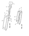
- Fig. 2D is partial elevational view of the blank also shown in Fig. 2C and illustrating a still further and substantially completed assembly step of the square female terminal;
- Fig. 2E is a plan view, similar to that shown in Fig. 2A, and illustrating a metal blank configurable into the round female terminal of Fig. 1B;
- Fig. 2F a side view illustration of the blank illustrated in Fig. 2E and showing its pre-configured and arcuate side profile;
- Fig. 2G is an illustration of an intermediate assembly condition of the metal blank of Fig. 1B;
- Fig. 2H is partial elevational view of the blank also shown in Fig. 2G and illustrating a still further and substantially completed assembly step of the round female terminal;
- Fig. 3A is a cutaway illustration of the square female terminal illustrated in Fig. 1A, and further showing the combined torsioned and angled contact beams in interengaging fashion with a square cross sectional male inserting pin;
- Fig. 3B is a cutaway illustration of the round female terminal illustrated in Fig. 1B, and further showing the combined torsional and angled contact beams in interengaging fashion with a square cross sectional male inserting pin;
- Fig. 4A is a further cutaway illustration of the square female terminal illustrated in Fig. 1A and further showing the combined torsioned and angled contact beams in interengaging fashion with a round cross sectional male inserting pin;
- Fig. 4B is a further cutaway illustration of the round female terminal shown in Fig. 1B, and further showing the combined torsional and angled contact beams in interengaging fashion with a round cross sectional male inserting pin;
- Fig. 5A is an open end view of the female terminal illustrated in Fig. 3A and showing the manner in which the male square pin interengages the female terminal;
- Fig. 5B is an open end view of the female terminal illustrated in Fig. 3B and showing the manner in which the square pin interengages the female terminal;
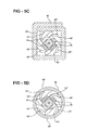
- Fig. 5C is an open end view of the female terminal illustrated in Fig. 4A and showing the manner in which the male round pin interengages the female terminal;
- Fig. 5D is an open end view of the female terminal illustrated in Fig. 4B and showing the manner in which the male round pin interengages the female terminal;
- Fig. 6A is an elongated cutaway view of the female terminal illustrated in Figs. 3A and 4A and showing, in plan cutaway, the combined angling and torsioning of the contact beams;
- Fig. 6B is an elongated cutaway view of the female terminal illustrated in Figs. 3B and 4B and showing, in plan cutaway, the combined angling and torsioning of the contact beams;
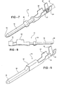
- Fig. 7 is a perspective illustration of an interengaging male terminal according to the present invention.
- Fig. 8 is a plan view of the male terminal as substantially illustrated in Fig. 7;
- Fig. 9 is perspective view of a male terminal exhibiting a square shaped inserting pin
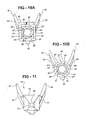
- Fig. 10A is an open end view of a square cross sectional and female terminal according to the present invention.
- Fig. 10B is an open end view of a round cross sectional and female terminal according to the present invention.
- Fig. 11 is an end view of the male terminal illustrated in Fig. 9;
- the present invention discloses a blank configurable and combination sleeve and spring cage.
- the construction of the female terminal is further such that both a greater area of electrical contact and increased normal holding forces are established with an associated and inserting pin of the male terminal.
- the present invention further discloses a method for configuring a metal and suitably electrically conductive blank into a female terminal.
- the male terminal can be constructed in a number of varying configurations and reference is made to a first variant 12 of the male terminal in Figs. 7 and 8 and a second variant 14 as shown in the perspective view of Fig. 9 and succeeding front end view of Fig. 11.
- male terminals can be constructed in particular fashion for use with the female terminal according to the present invention
- male terminals with inserting pins
- the variant 12 of male terminal exhibits an elongated and round cross sectional body largely consisting of a pin 18 with a pointed end 20 and an enlarged annular intermediate location 22.
- Wire crimping portions 22 and 24 extend from a further associated end of the male terminal and, upon being bent in inwardly opposing fashion, forcibly engage over an extending end of a wire or cable, see as illustrated at 26 in Fig. 7.
- the succeeding variant 14 of male terminal exhibits a substantially rectangular (square) cross sectional body again largely consisting of a pin 28 with a pointed end 30 and an enlarged annular intermediate location 32.
- Wire crimping portions 34 and 36 again extend from a further associated end of the male terminal and, upon being bent in inwardly opposing fashion, forcibly engage over an extending end of a wire or cable, not shown in these illustrations but substantially as seen as illustrated at 26 in the alternate variant of Fig. 7.
- the male terminal pin portions can range in cross sectional dimension to include such at 4.3 mm, 2.8 mm, 1.6 mm, 1.0 mm, 0.64 mm and 0.45 mm pin diameters among such possible sizes.
- a metal blank 48 is indicated and which is configurable into the female terminal 10 of Fig. 1A.
- the metal blank 48 is constructed of an electrically conductive material, such as a copper alloy, and includes a planar shaped main body 50, a plurality of angled, elongated and spaced apart beams 52 (see also carrier tab portions 51 and 53 and which in a preferred embodiment separate and support at opposite ends a plurality of at least three extending beams, here showing four beams by example) extending from a stem portion 54 interconnecting a first end of said main body 50, and wire crimping portions 56 and 58 extending from a second end of said main body 50 and interconnected by a further portion 60.
- an electrically conductive material such as a copper alloy
- the progressive method steps for forming the three dimensional female terminal are shown.
- the carrier tab portions 51 and 53 and spaced apart beams 52 are configured in the three dimensional and square shaped manner illustrated.
- the torsioning and angling of the beams 52, after the carrier tab portions 51 and 53 are initially bent into their three dimensional cross section, is further accomplished by inserting mandrels 55 and 57, exhibiting square shaped inserting portions, into tab portions 51 and 53.
- a series of forming tools bend the tab portions 51 and 53 in the manner shown in Fig. 2A along bending lines 70, in a certain forming sequence (the forming tools not being shown but understood to exist), until achieving a final square shape 51 and 53 in Fig. 2C.
- the preconfigured and arcuate side profile of the beams 52 are further constructed into an hourglass shape after the series of forming stations.
- the mandrels 55 and 57 (again Fig.
- a succeeding assembly step is illustrated and in which the planar shaped main body 50 is bent along a bending line 71 (see again Fig. 2A) in a pre-opening fashion 50 in Fig. 2C.
- a succeeding assembly step is illustrated and in which the angled, elongated and spaced apart beams 52 are folded inwardly along a bending line 73 (again Fig. 2C) and seated inside the main body 50, the body 50 then being folded around the beams 52 in a likewise square shaped fashion and in order to define an open inserting end (generally shown at 62 in Fig.
- a further wire or cable (see at 64 in phantom) is grippingly engaged by the inwardly folding of the crimping portions 56 and 58 and in order to electrically communicate the female terminal 10 in the same fashion as the cable 26 described in Fig. 8 likewise electrically communicates the associated male terminal 12.
- a metal blank 48' is indicated, which is a variant of the blank 10 forming the square shaped terminal 10 in Fig. 1A, and which is configurable into a round cross sectional female terminal 10' as shown in Fig. 1B.
- the metal blank 48' is again constructed of an electrically conductive material, such as a copper alloy, and includes a planar shaped main body 50', a plurality of angled, elongated and spaced apart beams 52' (see also carrier tab portions 51' and 53' and which in a preferred embodiment separate and support at opposite ends a plurality of at least three extending beams, here again showing four beams by example) extending from a stem portion 54' interconnecting a first end of the main body 50', and wire crimping portions 56' and 58' extending from a second end of said main body 50' and interconnected by a further portion 60'.
- an electrically conductive material such as a copper alloy
- the progressive method steps for forming the three dimensional round female terminal are shown.
- the carrier tab portions 51' and 53' and spaced apart beams 52' are configured in the three dimensional and round shaped manner illustrated.
- the torsioning and angling of the beams 52', after the carrier tab portions 51' and 53' are initially bent into their three dimensional and round cross section, is further accomplished by inserting mandrels 55' and 57', exhibiting round shaped inserting portions, into tab portions 51' and 53'.
- a series of forming tools bend the tab portion 51' and 53' in Fig. 2E in a certain forming sequence (the forming tools again not being shown but exist as known in the art), until achieving the final round shape 51' and 53', see further Fig. 2G.
- the preconfigured and arcuate side profile of the beams 52' are further constructed into an hourglass shape after the series of forming stations.
- mandrels 55' and 57' (corresponding to mandrel 57 in the previously disclosed embodiment) exist at every forming station, the purpose for which is to hold the two ends and to avoid metal walking out along a longitudinal direction during forming the beams into an hourglass shape, further effectuating the combined angling and torsioning of the beams 52'.
- a succeeding assembly step is illustrated and in which the planar shaped main body 50' is formed in a pre-opening fashion 50' (Fig. 2G).
- a succeeding assembly step is illustrated and in which the angled, elongated and spaced apart beams 52' are folded inwardly along a bending line 73' and seated inside the main body 50', the body 50' then being folded around the beams 52' in a likewise round shaped fashion and in order to define an open inserting end (generally shown at 62' in Fig. 1B) and within which is encased the angled, elongated and spaced apart beams 52'.
- the combined angling and torsional relationship of the elongated beams 52 is again illustrated in three dimension and to thereby facilitate both increased contact area (see Figs. 3A and 4A where beams 52 are wrapped along a male pin and therefore have lines of contact instead of points of contact) and normal holding forces established with the inserting pin end of the corresponding and interengaging male terminal.
- male terminal 14 having a rectangular (square) cross sectional inserting pin 28 is shown engaged within the open inserting end 62 of the female terminal 10 in Fig. 3 (see also end cutaway view of Figs. 5A and 5C and open end view of Fig. 10A in which both contacting portions 52 of the angled beams are illustrated as well as additional angling and overlapping portions contributing to the helix/hourglass shaped).
- the further variant of the male terminal 12 in Fig. 4A, with the round inserting pin 18, is illustrated in alternating fashion inserted into the open end 62 in Fig. 4.
- Figs. 3A and 4A The purpose of the illustrations in Figs. 3A and 4A is to stress that the design of the integral female terminal 10, and in particular that of the combined angled and torsioned beams 52, is such that a cross sectional configuration of any given male terminal pin (such as again has been previously described by example at 12, 14 or 16) is capable of being inserted into interengaging contact with the female terminal 10.
- round cross sectional female terminals illustrations are provided and which correspond to those presented at Figs. 3A and 4A. Accordingly, the same reference numerals are indicated, including angled beams 52', carrier tab portions 51' and 53', and outer body 50'.
- the round cross sectional male terminal 12, with round inserting pin portion 18, is further illustrated inserted within the open end 62' of the female terminal.
- Fig. 6B substantially identical to the previously described illustration of Fig. 6A
- the rounded and folded portions of the main body 50' of the female terminal main body which encircle the beams 52', again cause in combination with the mandrels 55' and 57' the combined angling and torsioning of the beams 52' into a substantially helix or hourglass shape (see as again generally represented at 72').
- Figs. 5B, 5D and 10B the open end of the female terminal is illustrated and by which the angled and torsioned beams (corresponding to references 52, 52' and 52" in Figs. 5A and 5C and repeated herein with the same reference numerals for ease of comparison) are shown in their ultimate configuration about a rectangular pin 28, referring further to Fig. 5B and round pin 28 in Fig. 5D, and in order to maximize the area of contact (see Figs. 3B and 4B where beam 52' wrapped along male pin and have line contacts) and corresponding normal inserting forces.
Landscapes
- Manufacturing Of Electrical Connectors (AREA)
- Connections Effected By Soldering, Adhesion, Or Permanent Deformation (AREA)
- Connector Housings Or Holding Contact Members (AREA)
Applications Claiming Priority (2)
| Application Number | Priority Date | Filing Date | Title |
|---|---|---|---|
| US10/428,528 US6860768B2 (en) | 2000-09-15 | 2003-05-01 | Combination sleeve and spring cage incorporated into a one-piece female terminal for interengaging a corresponding male terminal and method of configuring such a sleeve and spring cage from a blank shape |
| US428528 | 2003-05-01 |
Publications (2)
| Publication Number | Publication Date |
|---|---|
| EP1473803A2 true EP1473803A2 (de) | 2004-11-03 |
| EP1473803A3 EP1473803A3 (de) | 2005-12-21 |
Family
ID=32990481
Family Applications (1)
| Application Number | Title | Priority Date | Filing Date |
|---|---|---|---|
| EP04252552A Withdrawn EP1473803A3 (de) | 2003-05-01 | 2004-04-30 | Kombination aus Hülse und Federkäfig eingebaut in eine einstückige Buchse und Verfahren zum Bau einer solchen Kombination aus Hülse und Federkäfig aus einem Zuschnitt |
Country Status (4)
| Country | Link |
|---|---|
| US (1) | US6860768B2 (de) |
| EP (1) | EP1473803A3 (de) |
| CN (1) | CN100533864C (de) |
| CA (1) | CA2466125A1 (de) |
Cited By (1)
| Publication number | Priority date | Publication date | Assignee | Title |
|---|---|---|---|---|
| EP1705752A1 (de) | 2005-03-26 | 2006-09-27 | AMPHENOL-TUCHEL ELECTRONICS GmbH | Elektrische Steckverbinderbuchse |
Families Citing this family (19)
| Publication number | Priority date | Publication date | Assignee | Title |
|---|---|---|---|---|
| DE102007031619B4 (de) | 2007-07-09 | 2011-09-22 | Amphenol-Tuchel Electronics Gmbh | Elektrischer Steckverbinder |
| CH704749B1 (fr) * | 2007-09-05 | 2012-10-15 | Preci Dip Sa | Clip de contact. |
| CN101752715B (zh) * | 2008-12-11 | 2013-08-14 | 富士康(昆山)电脑接插件有限公司 | 线缆连接器 |
| CN102088136A (zh) * | 2009-12-03 | 2011-06-08 | 泰科电子(上海)有限公司 | 电连接端子 |
| JP5557378B2 (ja) * | 2010-03-23 | 2014-07-23 | 矢崎総業株式会社 | 圧着端子および圧着端子の電線に対する圧着構造 |
| WO2014129640A1 (ja) * | 2013-02-22 | 2014-08-28 | 古河電気工業株式会社 | 圧着端子の製造方法、圧着端子及びワイヤハーネス |
| EP2866306B1 (de) * | 2013-10-23 | 2020-07-29 | Aptiv Technologies Limited | Kontaktbuchse für eine elektrische Steckverbindung |
| US9362645B2 (en) * | 2013-12-05 | 2016-06-07 | Hypertronics Corporation | One piece socket contact |
| JP2015159092A (ja) * | 2014-02-25 | 2015-09-03 | 矢崎総業株式会社 | 接続端子 |
| JP2015159094A (ja) * | 2014-02-25 | 2015-09-03 | 矢崎総業株式会社 | 接続端子 |
| DE102015216632A1 (de) * | 2015-08-31 | 2017-03-02 | Te Connectivity Germany Gmbh | Anordnung zum Herstellen einer elektrischen Verbindung zwischen einem Flachkontakt und einem Hochstromleiter |
| KR20170088231A (ko) * | 2016-01-22 | 2017-08-01 | (주)에스피에스 | 마그네틱 커넥팅 장치 |
| DE112018000476B4 (de) | 2017-01-23 | 2023-06-15 | Molex, Llc | Elektrischer Anschlusskontakt und Verbinderanordnung damit |
| US10516238B2 (en) * | 2017-06-08 | 2019-12-24 | Delphi Technologies, Llc | Method for forming a shielded electrical terminal and an electrical terminal formed by said method |
| JP6588943B2 (ja) | 2017-06-20 | 2019-10-09 | 矢崎総業株式会社 | 端子接続構造 |
| USD882525S1 (en) * | 2018-01-30 | 2020-04-28 | Molex, Llc | Connector terminal |
| USD855574S1 (en) * | 2018-01-30 | 2019-08-06 | Molex, Llc | Connector terminal |
| EP4268330A4 (de) * | 2020-12-22 | 2025-01-29 | Molex, LLC | Elektrische anschlussklemme |
| CN115799874B (zh) * | 2023-02-02 | 2023-05-16 | 陕西四菱电子科技股份有限公司 | 一种冠簧连接器 |
Family Cites Families (14)
| Publication number | Priority date | Publication date | Assignee | Title |
|---|---|---|---|---|
| US3557428A (en) * | 1965-06-23 | 1971-01-26 | Connectronics Corp | Machines for manufacturing electric connector sockets |
| US4657335A (en) * | 1986-01-30 | 1987-04-14 | K & K Stamping | Radially resilient electrical socket |
| US4734063A (en) * | 1986-01-30 | 1988-03-29 | Joseph J. Koch | Radially resilient electric socket |
| EP0697752A3 (de) * | 1994-08-19 | 1996-05-29 | Whitaker Corp | Elektrische Anschlussbuchse |
| US6139374A (en) * | 1995-07-25 | 2000-10-31 | Framatome Connectors Interlock Inc. | Connector assembly |
| US5658175A (en) * | 1995-10-05 | 1997-08-19 | Itt Corporation | One-piece hooded socket contact and method of producing same |
| DE29705134U1 (de) * | 1997-03-20 | 1997-05-07 | Ingos Elektronik Handelsgesell | Steckerbuchse |
| JP3498832B2 (ja) * | 1998-09-10 | 2004-02-23 | 矢崎総業株式会社 | 雌型端子,雌型端子の組立方法及びコネクタハウジング |
| DE19933091A1 (de) * | 1999-07-15 | 2001-02-01 | Interconnectron Gmbh | Kontaktbuchse für elektrische Steckverbinder |
| US6152787A (en) * | 1999-08-30 | 2000-11-28 | Delphi Technologies, Inc. | One piece terminal |
| DE19941515A1 (de) * | 1999-08-31 | 2001-03-01 | Interconnectron Gmbh | Hochstromkontakt |
| US6358104B2 (en) * | 2000-01-10 | 2002-03-19 | Delphi Technologies, Inc. | High current terminal |
| US6656002B2 (en) * | 2000-09-15 | 2003-12-02 | Alcoa Fujikura Limited | Electrical terminal socket assembly including T shaped sealed connectors |
| US6264509B1 (en) * | 2001-01-10 | 2001-07-24 | Yazaki North America, Inc. | High cycle terminal with protected failsafe contact |
-
2003
- 2003-05-01 US US10/428,528 patent/US6860768B2/en not_active Expired - Fee Related
-
2004
- 2004-04-30 EP EP04252552A patent/EP1473803A3/de not_active Withdrawn
- 2004-05-01 CN CNB2004100639030A patent/CN100533864C/zh not_active Expired - Fee Related
- 2004-05-03 CA CA002466125A patent/CA2466125A1/en not_active Abandoned
Cited By (3)
| Publication number | Priority date | Publication date | Assignee | Title |
|---|---|---|---|---|
| EP1705752A1 (de) | 2005-03-26 | 2006-09-27 | AMPHENOL-TUCHEL ELECTRONICS GmbH | Elektrische Steckverbinderbuchse |
| DE102005013989A1 (de) * | 2005-03-26 | 2006-10-05 | Amphenol-Tuchel Electronics Gmbh | Elektrische Steckverbinderbuchse |
| DE102005013989B4 (de) * | 2005-03-26 | 2009-02-05 | Amphenol-Tuchel Electronics Gmbh | Elektrische Steckverbinderbuchse |
Also Published As
| Publication number | Publication date |
|---|---|
| US20040014370A1 (en) | 2004-01-22 |
| EP1473803A3 (de) | 2005-12-21 |
| CA2466125A1 (en) | 2004-11-01 |
| HK1072129A1 (zh) | 2005-08-12 |
| CN1574478A (zh) | 2005-02-02 |
| CN100533864C (zh) | 2009-08-26 |
| US6860768B2 (en) | 2005-03-01 |
Similar Documents
| Publication | Publication Date | Title |
|---|---|---|
| US6860768B2 (en) | Combination sleeve and spring cage incorporated into a one-piece female terminal for interengaging a corresponding male terminal and method of configuring such a sleeve and spring cage from a blank shape | |
| US6837756B2 (en) | Radially resilient electrical connector and method of making the same | |
| US5147230A (en) | Two piece electrical female terminal | |
| EP2141775B1 (de) | Elektrische Steckverbinder | |
| US5474479A (en) | Louvered contact electrical connector | |
| US6290556B1 (en) | Two piece male pin terminal connector | |
| US7611392B2 (en) | Terminal with integral strain relief | |
| EP0566038B1 (de) | Elektrische Anschlussbuchse | |
| US20030041453A1 (en) | Crimp dies, crimping tools and a process for crimping and pre-crimping an electrical connector | |
| JP2000077126A (ja) | リセプタクル型電気コンタクト | |
| EP0404349A2 (de) | Crimpmatrizensatz und Verfahren zum Crimpen eines elektrischen Anschlussendstücks | |
| EP0952631A2 (de) | Kontaktstift | |
| US10498048B2 (en) | Wire with terminal having a core crimping portion with enlarged diameter portion and a recess in the enlarged diameter portion | |
| US20100184340A1 (en) | Crimpable connector contact assembly for cable connector, cable connector and method for manufacturing thereof | |
| EP0568927B1 (de) | Elektrischer Buchsenkontakt | |
| EP0026117B1 (de) | Elektrischer Kontakt für einen elektrischen Steckverbinder und Verfahren zu dessen Herstellung | |
| EP3823099A1 (de) | Buchsenkontakt mit gefalteter buchse und verfahren zur herstellung | |
| US3818424A (en) | Electrical contact socket having improved contact spring | |
| US20190199007A1 (en) | Wire with terminal | |
| HK1072129B (en) | Combination sleeve and spring cage incorporated into a one-piece female terminal for interengaging a corresponding male terminal and method of configuring such a sleeve and spring cage from a blank shape | |
| EP0694991A1 (de) | Elektrischer Kontakt aus zwei Werkstoffen | |
| US20200067222A1 (en) | Terminal and method for producing terminal | |
| EP0841720A2 (de) | Abgedeckter elektrischer Verbinder | |
| EP0369739A1 (de) | Steckbuchse | |
| EP0986140A2 (de) | Elektrische Kontaktbuchse |
Legal Events
| Date | Code | Title | Description |
|---|---|---|---|
| PUAI | Public reference made under article 153(3) epc to a published international application that has entered the european phase |
Free format text: ORIGINAL CODE: 0009012 |
|
| AK | Designated contracting states |
Kind code of ref document: A2 Designated state(s): AT BE BG CH CY CZ DE DK EE ES FI FR GB GR HU IE IT LI LU MC NL PL PT RO SE SI SK TR |
|
| AX | Request for extension of the european patent |
Extension state: AL HR LT LV MK |
|
| PUAL | Search report despatched |
Free format text: ORIGINAL CODE: 0009013 |
|
| AK | Designated contracting states |
Kind code of ref document: A3 Designated state(s): AT BE BG CH CY CZ DE DK EE ES FI FR GB GR HU IE IT LI LU MC NL PL PT RO SE SI SK TR |
|
| AX | Request for extension of the european patent |
Extension state: AL HR LT LV MK |
|
| 17P | Request for examination filed |
Effective date: 20060608 |
|
| AKX | Designation fees paid |
Designated state(s): AT BE BG CH CY CZ DE DK EE ES FI FR GB GR HU IE IT LI LU MC NL PL PT RO SE SI SK TR |
|
| 17Q | First examination report despatched |
Effective date: 20060825 |
|
| GRAP | Despatch of communication of intention to grant a patent |
Free format text: ORIGINAL CODE: EPIDOSNIGR1 |
|
| STAA | Information on the status of an ep patent application or granted ep patent |
Free format text: STATUS: THE APPLICATION IS DEEMED TO BE WITHDRAWN |
|
| 18D | Application deemed to be withdrawn |
Effective date: 20091027 |