EP1473808A1 - Lampenfassung für zweiseitig gesockelte Leuchtstofflampen - Google Patents
Lampenfassung für zweiseitig gesockelte Leuchtstofflampen Download PDFInfo
- Publication number
- EP1473808A1 EP1473808A1 EP04003573A EP04003573A EP1473808A1 EP 1473808 A1 EP1473808 A1 EP 1473808A1 EP 04003573 A EP04003573 A EP 04003573A EP 04003573 A EP04003573 A EP 04003573A EP 1473808 A1 EP1473808 A1 EP 1473808A1
- Authority
- EP
- European Patent Office
- Prior art keywords
- rotor
- lamp
- lamp holder
- holder according
- socket
- Prior art date
- Legal status (The legal status is an assumption and is not a legal conclusion. Google has not performed a legal analysis and makes no representation as to the accuracy of the status listed.)
- Granted
Links
- 230000000295 complement effect Effects 0.000 claims description 3
- 238000003780 insertion Methods 0.000 claims description 3
- 230000037431 insertion Effects 0.000 claims description 3
- 239000000523 sample Substances 0.000 description 5
- 238000004519 manufacturing process Methods 0.000 description 3
- 238000009434 installation Methods 0.000 description 2
- 230000005540 biological transmission Effects 0.000 description 1
- 238000011990 functional testing Methods 0.000 description 1
- 238000002347 injection Methods 0.000 description 1
- 239000007924 injection Substances 0.000 description 1
- 238000001746 injection moulding Methods 0.000 description 1
- 239000000243 solution Substances 0.000 description 1
- 238000003466 welding Methods 0.000 description 1
Images


Classifications
-
- F—MECHANICAL ENGINEERING; LIGHTING; HEATING; WEAPONS; BLASTING
- F21—LIGHTING
- F21V—FUNCTIONAL FEATURES OR DETAILS OF LIGHTING DEVICES OR SYSTEMS THEREOF; STRUCTURAL COMBINATIONS OF LIGHTING DEVICES WITH OTHER ARTICLES, NOT OTHERWISE PROVIDED FOR
- F21V19/00—Fastening of light sources or lamp holders
- F21V19/0075—Fastening of light sources or lamp holders of tubular light sources, e.g. ring-shaped fluorescent light sources
- F21V19/008—Fastening of light sources or lamp holders of tubular light sources, e.g. ring-shaped fluorescent light sources of straight tubular light sources, e.g. straight fluorescent tubes, soffit lamps
-
- F—MECHANICAL ENGINEERING; LIGHTING; HEATING; WEAPONS; BLASTING
- F21—LIGHTING
- F21V—FUNCTIONAL FEATURES OR DETAILS OF LIGHTING DEVICES OR SYSTEMS THEREOF; STRUCTURAL COMBINATIONS OF LIGHTING DEVICES WITH OTHER ARTICLES, NOT OTHERWISE PROVIDED FOR
- F21V19/00—Fastening of light sources or lamp holders
- F21V19/04—Fastening of light sources or lamp holders with provision for changing light source, e.g. turret
-
- H—ELECTRICITY
- H01—ELECTRIC ELEMENTS
- H01R—ELECTRICALLY-CONDUCTIVE CONNECTIONS; STRUCTURAL ASSOCIATIONS OF A PLURALITY OF MUTUALLY-INSULATED ELECTRICAL CONNECTING ELEMENTS; COUPLING DEVICES; CURRENT COLLECTORS
- H01R33/00—Coupling devices specially adapted for supporting apparatus and having one part acting as a holder providing support and electrical connection via a counterpart which is structurally associated with the apparatus, e.g. lamp holders; Separate parts thereof
- H01R33/05—Two-pole devices
- H01R33/06—Two-pole devices with two current-carrying pins, blades or analogous contacts, having their axes parallel to each other
- H01R33/08—Two-pole devices with two current-carrying pins, blades or analogous contacts, having their axes parallel to each other for supporting tubular fluorescent lamp
- H01R33/0836—Two-pole devices with two current-carrying pins, blades or analogous contacts, having their axes parallel to each other for supporting tubular fluorescent lamp characterised by the lamp holding means
- H01R33/0854—Two-pole devices with two current-carrying pins, blades or analogous contacts, having their axes parallel to each other for supporting tubular fluorescent lamp characterised by the lamp holding means with lamp rotating means
Definitions
- the invention relates to a lamp holder for two-sided socketed, each having two lamp pins parallel to the lamp Fluorescent lamps with a socket housing and in it located contacts and with a rotatable in the socket body mounted rotor, which has a guide slot to cross the lamp axis Introducing the lamp base pins
- DE 94 09 147 U1 is an installation and removal aid for changing of double-ended fluorescent lamps known as elongated board can be plugged onto the contact pins of the lamp and accessible from the outside between the lamp base when installed and lamp holder.
- the board either points two through holes for inserting the lamp contact pins on or one or more slots for subsequent insertion the circuit board onto the lamp contact pins.
- the circuit board is rotatably connected to the lamp base.
- the board is a separate tool in one variant is carried out, if necessary, to the lamp contact pins the disadvantage is that this separate tool easily get lost or awkward near the lamp is to be kept, which also contains the probability that it is not available when needed.
- the board is permanently connected to the lamp contact pins leave it to be noted that the board has a Thread the lamp onto its contact pins and in the event of a lamp change be removed from the lamp to be removed got to.
- the object of the invention is therefore based on a lamp holder of the aforementioned type available make that is very easy to handle and always when needed is reliably available.
- the invention is characterized by an actuator for the rotor of the lamp holder, the flat and essentially disc-shaped and on the View face of the rotor is attached and one in the control panel arranged slot is aligned with the guide slot and thereby, that the control unit has at least one substantially radial to the lamp axis Aligned actuating arm that over the The scope of the socket body protrudes.
- control element in the sense of a rotor actuator is permanently attached to the rotor, it is always available when needed and cannot be lost. Easy handling is guaranteed because the control element at least over the scope of Bulb body protrudes, which is usually no larger than that Lamp base diameter. Otherwise the projection of the The control element can of course also be designed so that the Exceeded the circumference of the lamp base.
- the invention also has further advantages Rotor-attached control element transmits the manual operating forces directly on the rotor, which in turn is the lamp contact pins in the direction of rotation. So it will be the Lamp contact pins are gentle on the rotor and not on a force-introducing one Tool applied
- the control element is a very simple, small component represents that e.g. as a plastic injection molded part in a little complex injection molding tool can be manufactured.
- the invention has the advantage that commercially available rotor mounts with this control element, i.e. after completing their basic manufacturing can be equipped.
- An inventive Lamp holder therefore does not require a special manufacturing stage in a production process This simplifies Disposition at the frame manufacturer, who only needs the one currently required Number of standard sockets to be equipped with one control element need
- control element essentially positively and / or non-positively connected to the rotor be, for example, firmly clamped or snapped onto it his.
- the Control element on its rear facing the rotor with be provided with at least one plug or locking pin for engagement in at least one complementary breakthrough of the rotor.
- This Execution is particularly interesting for rotor mounts, whose rotor has so-called "test probe openings" in the front, that allow the insertion of test probes that the behind these Breakthrough socket contacts for the functional test of the Apply light.
- the invention does that Take advantage of the presence of such holes in the rotor to to fix the control element in it by means of corresponding pins.
- control element itself can in turn have openings, that are aligned with the probe tip openings of the rotor and thus the Continue to guarantee the function of the frame check.
- this can Control element on its rear facing the rotor with a Be provided with a depression, the outline of which corresponds to the outline of the rotor is adjusted.
- This is a shape adjustment between the control element and rotor given an optimal power transmission from Operating element on the rotor guaranteed when it is turned.
- a lamp socket designated overall by 10, serves one another opposite arrangement as a pair of sockets for mounting and for the electrical connection of a two-sided, not shown socketed fluorescent lamp.
- FIG.1 A classic installation situation of such a lamp holder 10 in a lamp 11 shows Fig.1. Of this lamp 11 are on an extruded profile luminaire housing 12 and a reflector 13 arranged therein is shown. It is essential that the spatial conditions laterally next to the sockets 10 and so only very narrow next to the lamp held by them Leave column 14 when inserting or replacing one Do not allow lamp access by hand or at best design extremely cumbersome.
- control panel 15 for Rotation of the rotor 19 of a rotor mount 10 which has a handle 16 projecting beyond the lamp holder 10, which can be easily gripped by hand from the outside.
- this control panel 15 and its arrangements are best made the figures explained below understandable.
- the control unit 15 has a corresponding to FIGS. 2 to 5 plate-like, thin base body 17, one of which is designated by 18, contains longitudinal slit open on one side.
- Rotor 19 also has slots 20 which are generally shown in FIG known way of inserting the socket contact pins of a tubular Serve fluorescent lamp. Usually after Insert the lamp and then turn it about 90 ° around its longitudinal axis, the socket contact pins with the socket 10 contacts located in the functional position. At the same time the lamp with its base contact pins across the guide slots 20 oriented so that they do not fall out of the sockets 10 can.
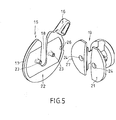
- the operating member 15 with the rotor 19 firmly connected e.g. by being on the face 21 of the rotor 19 glued on or with the rotor 19, in particular by means of ultrasonic welding is connected
- the operating member 15 can be on its rear surface or back 22 (Fig. 5) but also with plug or plug-in locking pin 23 may be provided. These are used to engage in So-called test probe openings 24, through the test probes of a function test device introduced to the socket contacts behind it can be.
Landscapes
- Engineering & Computer Science (AREA)
- General Engineering & Computer Science (AREA)
- Fastening Of Light Sources Or Lamp Holders (AREA)
- Connecting Device With Holders (AREA)
Abstract
Description
- Fig. 1
- einen schematischen Querschnitt durch ein Leuchtengehause mit Blick auf die Innenseite einer darin befindlichen erfindungsgemäßen Lampenfassung.
- Fig. 2
- eine Frontansicht einer ähnlichen Lampenfassung,
- Fig 3
- eine perspektivische Ansicht der Lampenfassung nach Fig. 2,
- Fig. 4
- eine Explosionsdarstellung der Fassung nach den Fig 2 und 3 in einer der Fig. 3 entsprechenden Blickrichtung, und
- Fig. 5
- eine Explosionsansicht eines Rotors mit davor verschwenkt dargestelltem Bedienglied, um dessen rückwärtige oder innere Gestaltung zu veranschaulichen.
Claims (8)
- Lampenfassung (10) für zweiseitig gesockelte, jeweils zwei lampenachsparallele Sockelstifte aufweisende Leuchtstofflampen, mit einem Fassungsgehäuse und darin befindlichen Kontakten sowie mit einem im Fassungskörper drehbar gelagerten Rotor (19), der einen Führungsschlitz (20) zum lampenachsqueren Einfuhren der Lampensockelstifte aufweist, gekennzeichnet durch ein Betätigungsglied (15) für den Rotor (19) der Lampenfassung (10), das flach und im wesentlichen scheibenförmig ausgebildet und an der Ansichtsfläche (21) des Rotors (19) befestigt ist und dabei ein im Bedienteil (15) angeordneter Schlitz (18) mit dem Führungsschlitz (20) fluchtet und dadurch, dass das Bedienteil (15) wenigstens einen im wesentlichen radial zur Lampenachse ausgerichteten Betätigungsarm (16) aufweist, der über den Umfang des Fassungskörpers (10) vorsteht.
- Lampenfassung nach Anspruch 1, dadurch gekennzeichnet, dass das Bedienglied (15) im wesentlichen form- und/oder rastschlüssig mit dem Rotor (19) verbunden ist.
- Lampenfassung nach Anspruch 2, dadurch gekennzeichnet, dass das Bedienglied (15) auf seiner dem Rotor (19) zugewandten Rückseite (22) mit wenigstens einem Steck- oder Rastzapfen (23) versehen ist zum Eingriff in wenigstens einen komplementären, vom Führungsschlitz (20) unabhängigen Durchbruch (24) des Rotors (19).
- Lampenfassung nach einem der vorhergehenden Ansprüche, dadurch gekennzeichnet, dass das Bedienglied (15) mit dem Rotor (19) verklebt oder verschweißt ist.
- Lampenfassung nach Anspruch 4, dadurch gekennzeichnet, dass das Bedienglied (15) auf die Ansichtsfläche (21) des Rotors aufgeklebt oder aufgeschweißt ist.
- Lampenfassung nach einem der vorhergehenden Ansprüche, dadurch gekennzeichnet, dass das Bedienglied (15) Durchbrüche (25) aufweist, die mit sog. Prüfspitzenöffnungen (24) des Rotors (19) fluchten.
- Lampenfassung nach einem der vorhergehenden Ansprüche, dadurch gekennzeichnet, dass das Bedienglied (15) auf seiner dem Rotor (19) zugewandten Rückseite (22) mit einer Einsenkung (26) versehen ist, deren Umriss an den Umfang (27) der Ansichtsfläche (21) des Rotors (19) angepasst ist.
- Lampenfassung nach einem der vorhergehenden Ansprüche, dadurch gekennzeichnet, dass das Bedienglied (15) über den Umfang der Lampensockels vorsteht.
Applications Claiming Priority (2)
| Application Number | Priority Date | Filing Date | Title |
|---|---|---|---|
| DE10319431 | 2003-04-29 | ||
| DE10319431A DE10319431B4 (de) | 2003-04-29 | 2003-04-29 | Lampenfassung für zweiseitig gesockelte Leuchtstofflampen |
Publications (2)
| Publication Number | Publication Date |
|---|---|
| EP1473808A1 true EP1473808A1 (de) | 2004-11-03 |
| EP1473808B1 EP1473808B1 (de) | 2011-11-09 |
Family
ID=32981172
Family Applications (1)
| Application Number | Title | Priority Date | Filing Date |
|---|---|---|---|
| EP04003573A Expired - Lifetime EP1473808B1 (de) | 2003-04-29 | 2004-02-18 | Lampenfassung für zweiseitig gesockelte Leuchtstofflampen |
Country Status (5)
| Country | Link |
|---|---|
| US (1) | US6890199B2 (de) |
| EP (1) | EP1473808B1 (de) |
| JP (1) | JP4066056B2 (de) |
| AT (1) | ATE533210T1 (de) |
| DE (1) | DE10319431B4 (de) |
Cited By (1)
| Publication number | Priority date | Publication date | Assignee | Title |
|---|---|---|---|---|
| CN102656405A (zh) * | 2009-12-01 | 2012-09-05 | 宗拓贝尔照明器材有限公司 | 具有用于光射出元件的可移动保持元件的灯具 |
Families Citing this family (20)
| Publication number | Priority date | Publication date | Assignee | Title |
|---|---|---|---|---|
| US7448892B2 (en) * | 2004-12-20 | 2008-11-11 | Leviton Manufacturing Corporation | Fluorescent lamp holder with integral locking mechanism |
| US7097327B1 (en) * | 2005-03-21 | 2006-08-29 | Daniel W Barton | Lever pivot safety stop socket for fluorescent lamps |
| CN101288207A (zh) * | 2005-04-18 | 2008-10-15 | 立维腾制造有限公司 | T-8型至t-5型适配器灯座 |
| US7344398B2 (en) * | 2005-09-01 | 2008-03-18 | C.E.I.T. Corp. | Safety locking socket for light tube |
| US7484979B2 (en) * | 2006-08-04 | 2009-02-03 | Vode Lighting Inc. | Hub assembly |
| JP4291345B2 (ja) * | 2006-09-01 | 2009-07-08 | ホシデン株式会社 | 接続装置 |
| US8105101B2 (en) * | 2007-01-26 | 2012-01-31 | Panasonic Electric Works Co., Ltd. | Lamp socket and luminaire with same |
| JP5038779B2 (ja) * | 2007-01-26 | 2012-10-03 | パナソニック株式会社 | ランプソケット装置およびそれを備えた照明器具 |
| JP4936451B2 (ja) * | 2007-02-19 | 2012-05-23 | パナソニック株式会社 | ランプソケット装置およびそれを備えた照明器具 |
| JP4867697B2 (ja) * | 2007-02-19 | 2012-02-01 | パナソニック電工株式会社 | ランプソケット装置およびそれを備えた照明器具 |
| JP4775295B2 (ja) * | 2007-03-27 | 2011-09-21 | パナソニック電工株式会社 | 照明器具 |
| JP5054504B2 (ja) * | 2007-12-20 | 2012-10-24 | パナソニック株式会社 | ランプソケット及び照明器具 |
| JP5060271B2 (ja) * | 2007-12-20 | 2012-10-31 | パナソニック株式会社 | ランプソケット及び照明器具 |
| JP5118561B2 (ja) * | 2008-06-20 | 2013-01-16 | パナソニック株式会社 | ランプソケット及び照明器具 |
| CN102077018A (zh) * | 2008-07-02 | 2011-05-25 | 夏普株式会社 | 光源装置和显示装置 |
| GR1006750B (el) * | 2009-02-04 | 2010-04-08 | Pilux & Danpex Ae | Μετατροπεας προσαρμοζομενος σε φωτιστικα φθορισμου για χρηση λαμπτηρων τ5 και τ8 |
| US7963661B2 (en) * | 2009-02-09 | 2011-06-21 | American Greetings Corporation | Display light fixtures |
| US8333602B2 (en) * | 2011-01-06 | 2012-12-18 | Leviton Manufacturing Co., Inc. | Lamp socket having a rotor |
| US8475189B2 (en) * | 2011-05-27 | 2013-07-02 | Chuan He Co., Ltd. | Connection unit for fluorescent tubes |
| US8475190B2 (en) * | 2011-05-27 | 2013-07-02 | Chuan He Co., Ltd. | Connection unit for fluorescent tubes |
Citations (3)
| Publication number | Priority date | Publication date | Assignee | Title |
|---|---|---|---|---|
| DE2938247B1 (de) | 1979-09-21 | 1980-10-30 | Hoffmeister Leuchten Kg | Lampenfassung fuer Leuchtstoffroehren |
| US4306758A (en) | 1979-02-26 | 1981-12-22 | Leviton Manufacturing Company, Inc. | Lamp holder with self-locking device |
| DE9409147U1 (de) | 1994-06-06 | 1994-09-29 | Forchheim & Willing GmbH, 09387 Leukersdorf | Ein- und Ausbauhilfe zum Wechsel von zweiseitig gesockelten Leuchtstofflampen |
Family Cites Families (8)
| Publication number | Priority date | Publication date | Assignee | Title |
|---|---|---|---|---|
| US3896334A (en) * | 1973-08-15 | 1975-07-22 | Creative Tech Corp | Multiple level lamp adapter |
| US4101956A (en) * | 1976-11-26 | 1978-07-18 | Keene Corporation | Fluorescent fixture |
| US4565431A (en) * | 1984-12-24 | 1986-01-21 | Eastman Kodak Company | Photographic camera and flash assembly |
| ES2012522A6 (es) * | 1987-12-21 | 1990-04-01 | Olabarri Bustillo Francisco Ja | Dispositivo para la manipulacion de lamparas en lugares de dificil acceso. |
| JP3104167B2 (ja) * | 1996-05-10 | 2000-10-30 | モレックス インコーポレーテッド | 蛍光灯用ソケット |
| US6420434B1 (en) * | 2000-06-02 | 2002-07-16 | The United States Of America As Represented By The Secretary Of The Army | Active topical skin protectants using polyoxometallates |
| JP2002160581A (ja) * | 2000-11-24 | 2002-06-04 | Koito Mfg Co Ltd | 車輌用灯具及び回動用駆動装置 |
| US6488510B2 (en) * | 2001-03-21 | 2002-12-03 | Long-Beam Enterprise Co., Ltd. | Rotary-plug wall lamp |
-
2003
- 2003-04-29 DE DE10319431A patent/DE10319431B4/de not_active Expired - Fee Related
-
2004
- 2004-02-18 AT AT04003573T patent/ATE533210T1/de active
- 2004-02-18 EP EP04003573A patent/EP1473808B1/de not_active Expired - Lifetime
- 2004-02-26 US US10/788,671 patent/US6890199B2/en not_active Expired - Fee Related
- 2004-04-28 JP JP2004160285A patent/JP4066056B2/ja not_active Expired - Fee Related
Patent Citations (3)
| Publication number | Priority date | Publication date | Assignee | Title |
|---|---|---|---|---|
| US4306758A (en) | 1979-02-26 | 1981-12-22 | Leviton Manufacturing Company, Inc. | Lamp holder with self-locking device |
| DE2938247B1 (de) | 1979-09-21 | 1980-10-30 | Hoffmeister Leuchten Kg | Lampenfassung fuer Leuchtstoffroehren |
| DE9409147U1 (de) | 1994-06-06 | 1994-09-29 | Forchheim & Willing GmbH, 09387 Leukersdorf | Ein- und Ausbauhilfe zum Wechsel von zweiseitig gesockelten Leuchtstofflampen |
Cited By (1)
| Publication number | Priority date | Publication date | Assignee | Title |
|---|---|---|---|---|
| CN102656405A (zh) * | 2009-12-01 | 2012-09-05 | 宗拓贝尔照明器材有限公司 | 具有用于光射出元件的可移动保持元件的灯具 |
Also Published As
| Publication number | Publication date |
|---|---|
| DE10319431B4 (de) | 2005-05-25 |
| US20040219814A1 (en) | 2004-11-04 |
| ATE533210T1 (de) | 2011-11-15 |
| US6890199B2 (en) | 2005-05-10 |
| JP4066056B2 (ja) | 2008-03-26 |
| DE10319431A1 (de) | 2005-01-05 |
| EP1473808B1 (de) | 2011-11-09 |
| JP2005294239A (ja) | 2005-10-20 |
Similar Documents
| Publication | Publication Date | Title |
|---|---|---|
| DE10319431B4 (de) | Lampenfassung für zweiseitig gesockelte Leuchtstofflampen | |
| EP1467056A2 (de) | Garagentorantrieb mit Leuchteinheit | |
| DE102005015973A1 (de) | Befestigungsvorrichtung für mindestens einen Sensor an einer Fahrzeugscheibe | |
| EP0187296B1 (de) | Fassungsträger mit einer schwenkbaren Fassung für einseitig gesockelte Leuchtstofflampen | |
| DE69015097T2 (de) | Kraftfahrzeugskarosseriekomponente, umfassend eine Beleuchtungsvorrichtung. | |
| EP0024363A1 (de) | Elektrische Lampe mit einem hülsenförmigen Sockel | |
| DE102007056280B3 (de) | Fahrzeuglampe | |
| DE102012206188A1 (de) | Leuchtröhre und Verfahren zum Herstellen einer Leuchtröhre | |
| DE69822990T2 (de) | Lenkstockschalter mit Drehverbinder | |
| DE3803933A1 (de) | Kraftfahrzeugscheinwerfer | |
| DE102019130176B4 (de) | Steckverbinderteil mit einer Rasteinrichtung | |
| DE60002670T2 (de) | Lampenadapter mit integriertem elektronischen vorschaltgerät zur aufnahme von hochleistunsleuchtstofflampen, zum ersetzen von leuchtstofflampen mit einem induktiven vorschaltgerät | |
| WO2006111413A1 (de) | Fahrzeugleuchte mit einem im einbauzustand lösbaren bauteil | |
| EP0664583B1 (de) | Fassung für Kleinglühlampe | |
| DE19951077C1 (de) | Stellantrieb zum Verstellen eines Stellglieds in zumindest zwei Freiheitsgraden | |
| DE20306699U1 (de) | Lampenfassung für zweiseitig gesockelte Leuchtstofflampen | |
| DE102016117552B4 (de) | Drehlager zur drehbaren Aufnahme eines Lichtmoduls in einem Tragrahmen eines Scheinwerfers | |
| DE2938247C2 (de) | Lampenfassung für Leuchtstoffröhren | |
| DE202011051616U1 (de) | Eine LED-Innenleuchte | |
| EP0409935B1 (de) | Elektromechanische schaltuhr | |
| DE1603276C3 (de) | Drehbühnenanlage für Spielzeug- und Modelleisenbahnen | |
| DE102016107147B4 (de) | Schaltschrankleuchte mit verstellbarer Leuchtmittelplatine | |
| DE10035528B4 (de) | Leuchte, insbesondere Leseleuchte für Fahrzeuge | |
| EP1790814A1 (de) | Garagentorantrieb mit Leuchteinheit | |
| EP2453170B1 (de) | Befestigungsvorrichtung für Sensoren an Leuchten |
Legal Events
| Date | Code | Title | Description |
|---|---|---|---|
| PUAI | Public reference made under article 153(3) epc to a published international application that has entered the european phase |
Free format text: ORIGINAL CODE: 0009012 |
|
| AK | Designated contracting states |
Kind code of ref document: A1 Designated state(s): AT BE BG CH CY CZ DE DK EE ES FI FR GB GR HU IE IT LI LU MC NL PT RO SE SI SK TR |
|
| AX | Request for extension of the european patent |
Extension state: AL LT LV MK |
|
| 17P | Request for examination filed |
Effective date: 20050201 |
|
| AKX | Designation fees paid |
Designated state(s): AT BE BG CH CY CZ DE DK EE ES FI FR GB GR HU IE IT LI LU MC NL PT RO SE SI SK TR |
|
| 17Q | First examination report despatched |
Effective date: 20100129 |
|
| GRAP | Despatch of communication of intention to grant a patent |
Free format text: ORIGINAL CODE: EPIDOSNIGR1 |
|
| GRAS | Grant fee paid |
Free format text: ORIGINAL CODE: EPIDOSNIGR3 |
|
| GRAA | (expected) grant |
Free format text: ORIGINAL CODE: 0009210 |
|
| AK | Designated contracting states |
Kind code of ref document: B1 Designated state(s): AT BE BG CH CY CZ DE DK EE ES FI FR GB GR HU IE IT LI LU MC NL PT RO SE SI SK TR |
|
| REG | Reference to a national code |
Ref country code: GB Ref legal event code: FG4D Free format text: NOT ENGLISH |
|
| REG | Reference to a national code |
Ref country code: CH Ref legal event code: EP |
|
| REG | Reference to a national code |
Ref country code: IE Ref legal event code: FG4D Free format text: LANGUAGE OF EP DOCUMENT: GERMAN |
|
| REG | Reference to a national code |
Ref country code: DE Ref legal event code: R096 Ref document number: 502004013035 Country of ref document: DE Effective date: 20111229 |
|
| REG | Reference to a national code |
Ref country code: NL Ref legal event code: VDEP Effective date: 20111109 |
|
| PG25 | Lapsed in a contracting state [announced via postgrant information from national office to epo] |
Ref country code: SI Free format text: LAPSE BECAUSE OF FAILURE TO SUBMIT A TRANSLATION OF THE DESCRIPTION OR TO PAY THE FEE WITHIN THE PRESCRIBED TIME-LIMIT Effective date: 20111109 Ref country code: GR Free format text: LAPSE BECAUSE OF FAILURE TO SUBMIT A TRANSLATION OF THE DESCRIPTION OR TO PAY THE FEE WITHIN THE PRESCRIBED TIME-LIMIT Effective date: 20120210 Ref country code: PT Free format text: LAPSE BECAUSE OF FAILURE TO SUBMIT A TRANSLATION OF THE DESCRIPTION OR TO PAY THE FEE WITHIN THE PRESCRIBED TIME-LIMIT Effective date: 20120309 Ref country code: NL Free format text: LAPSE BECAUSE OF FAILURE TO SUBMIT A TRANSLATION OF THE DESCRIPTION OR TO PAY THE FEE WITHIN THE PRESCRIBED TIME-LIMIT Effective date: 20111109 Ref country code: SE Free format text: LAPSE BECAUSE OF FAILURE TO SUBMIT A TRANSLATION OF THE DESCRIPTION OR TO PAY THE FEE WITHIN THE PRESCRIBED TIME-LIMIT Effective date: 20111109 |
|
| REG | Reference to a national code |
Ref country code: IE Ref legal event code: FD4D |
|
| REG | Reference to a national code |
Ref country code: DE Ref legal event code: R082 Ref document number: 502004013035 Country of ref document: DE Representative=s name: PATENTANWAELTE OSTRIGA, SONNET, WIRTHS & VORWE, DE |
|
| PG25 | Lapsed in a contracting state [announced via postgrant information from national office to epo] |
Ref country code: CY Free format text: LAPSE BECAUSE OF FAILURE TO SUBMIT A TRANSLATION OF THE DESCRIPTION OR TO PAY THE FEE WITHIN THE PRESCRIBED TIME-LIMIT Effective date: 20111109 |
|
| PG25 | Lapsed in a contracting state [announced via postgrant information from national office to epo] |
Ref country code: DK Free format text: LAPSE BECAUSE OF FAILURE TO SUBMIT A TRANSLATION OF THE DESCRIPTION OR TO PAY THE FEE WITHIN THE PRESCRIBED TIME-LIMIT Effective date: 20111109 Ref country code: SK Free format text: LAPSE BECAUSE OF FAILURE TO SUBMIT A TRANSLATION OF THE DESCRIPTION OR TO PAY THE FEE WITHIN THE PRESCRIBED TIME-LIMIT Effective date: 20111109 Ref country code: IE Free format text: LAPSE BECAUSE OF FAILURE TO SUBMIT A TRANSLATION OF THE DESCRIPTION OR TO PAY THE FEE WITHIN THE PRESCRIBED TIME-LIMIT Effective date: 20111109 Ref country code: EE Free format text: LAPSE BECAUSE OF FAILURE TO SUBMIT A TRANSLATION OF THE DESCRIPTION OR TO PAY THE FEE WITHIN THE PRESCRIBED TIME-LIMIT Effective date: 20111109 Ref country code: BG Free format text: LAPSE BECAUSE OF FAILURE TO SUBMIT A TRANSLATION OF THE DESCRIPTION OR TO PAY THE FEE WITHIN THE PRESCRIBED TIME-LIMIT Effective date: 20120209 Ref country code: CZ Free format text: LAPSE BECAUSE OF FAILURE TO SUBMIT A TRANSLATION OF THE DESCRIPTION OR TO PAY THE FEE WITHIN THE PRESCRIBED TIME-LIMIT Effective date: 20111109 |
|
| BERE | Be: lapsed |
Owner name: BJB G.M.B.H. & CO. KG Effective date: 20120228 |
|
| PG25 | Lapsed in a contracting state [announced via postgrant information from national office to epo] |
Ref country code: RO Free format text: LAPSE BECAUSE OF FAILURE TO SUBMIT A TRANSLATION OF THE DESCRIPTION OR TO PAY THE FEE WITHIN THE PRESCRIBED TIME-LIMIT Effective date: 20111109 |
|
| PLBE | No opposition filed within time limit |
Free format text: ORIGINAL CODE: 0009261 |
|
| STAA | Information on the status of an ep patent application or granted ep patent |
Free format text: STATUS: NO OPPOSITION FILED WITHIN TIME LIMIT |
|
| PG25 | Lapsed in a contracting state [announced via postgrant information from national office to epo] |
Ref country code: MC Free format text: LAPSE BECAUSE OF NON-PAYMENT OF DUE FEES Effective date: 20120229 |
|
| REG | Reference to a national code |
Ref country code: CH Ref legal event code: PL |
|
| 26N | No opposition filed |
Effective date: 20120810 |
|
| GBPC | Gb: european patent ceased through non-payment of renewal fee |
Effective date: 20120218 |
|
| PG25 | Lapsed in a contracting state [announced via postgrant information from national office to epo] |
Ref country code: LI Free format text: LAPSE BECAUSE OF NON-PAYMENT OF DUE FEES Effective date: 20120229 Ref country code: CH Free format text: LAPSE BECAUSE OF NON-PAYMENT OF DUE FEES Effective date: 20120229 |
|
| REG | Reference to a national code |
Ref country code: DE Ref legal event code: R097 Ref document number: 502004013035 Country of ref document: DE Effective date: 20120810 |
|
| PG25 | Lapsed in a contracting state [announced via postgrant information from national office to epo] |
Ref country code: BE Free format text: LAPSE BECAUSE OF NON-PAYMENT OF DUE FEES Effective date: 20120228 |
|
| PG25 | Lapsed in a contracting state [announced via postgrant information from national office to epo] |
Ref country code: GB Free format text: LAPSE BECAUSE OF NON-PAYMENT OF DUE FEES Effective date: 20120218 |
|
| REG | Reference to a national code |
Ref country code: AT Ref legal event code: MM01 Ref document number: 533210 Country of ref document: AT Kind code of ref document: T Effective date: 20120218 |
|
| PG25 | Lapsed in a contracting state [announced via postgrant information from national office to epo] |
Ref country code: ES Free format text: LAPSE BECAUSE OF FAILURE TO SUBMIT A TRANSLATION OF THE DESCRIPTION OR TO PAY THE FEE WITHIN THE PRESCRIBED TIME-LIMIT Effective date: 20120220 |
|
| PGFP | Annual fee paid to national office [announced via postgrant information from national office to epo] |
Ref country code: FR Payment date: 20130315 Year of fee payment: 10 |
|
| PG25 | Lapsed in a contracting state [announced via postgrant information from national office to epo] |
Ref country code: FI Free format text: LAPSE BECAUSE OF FAILURE TO SUBMIT A TRANSLATION OF THE DESCRIPTION OR TO PAY THE FEE WITHIN THE PRESCRIBED TIME-LIMIT Effective date: 20111109 Ref country code: AT Free format text: LAPSE BECAUSE OF NON-PAYMENT OF DUE FEES Effective date: 20120218 |
|
| PG25 | Lapsed in a contracting state [announced via postgrant information from national office to epo] |
Ref country code: TR Free format text: LAPSE BECAUSE OF FAILURE TO SUBMIT A TRANSLATION OF THE DESCRIPTION OR TO PAY THE FEE WITHIN THE PRESCRIBED TIME-LIMIT Effective date: 20111109 |
|
| PG25 | Lapsed in a contracting state [announced via postgrant information from national office to epo] |
Ref country code: LU Free format text: LAPSE BECAUSE OF NON-PAYMENT OF DUE FEES Effective date: 20120218 |
|
| PG25 | Lapsed in a contracting state [announced via postgrant information from national office to epo] |
Ref country code: HU Free format text: LAPSE BECAUSE OF FAILURE TO SUBMIT A TRANSLATION OF THE DESCRIPTION OR TO PAY THE FEE WITHIN THE PRESCRIBED TIME-LIMIT Effective date: 20040218 |
|
| REG | Reference to a national code |
Ref country code: FR Ref legal event code: ST Effective date: 20141031 |
|
| PG25 | Lapsed in a contracting state [announced via postgrant information from national office to epo] |
Ref country code: FR Free format text: LAPSE BECAUSE OF NON-PAYMENT OF DUE FEES Effective date: 20140228 |
|
| PGFP | Annual fee paid to national office [announced via postgrant information from national office to epo] |
Ref country code: IT Payment date: 20180221 Year of fee payment: 15 |
|
| PGFP | Annual fee paid to national office [announced via postgrant information from national office to epo] |
Ref country code: DE Payment date: 20181227 Year of fee payment: 16 |
|
| PG25 | Lapsed in a contracting state [announced via postgrant information from national office to epo] |
Ref country code: IT Free format text: LAPSE BECAUSE OF NON-PAYMENT OF DUE FEES Effective date: 20190218 |
|
| REG | Reference to a national code |
Ref country code: DE Ref legal event code: R119 Ref document number: 502004013035 Country of ref document: DE |
|
| PG25 | Lapsed in a contracting state [announced via postgrant information from national office to epo] |
Ref country code: DE Free format text: LAPSE BECAUSE OF NON-PAYMENT OF DUE FEES Effective date: 20200901 |