EP1475164A2 - Générateur de marche simulée pour mesures phonométriques dans l'industrie du bâtiment - Google Patents
Générateur de marche simulée pour mesures phonométriques dans l'industrie du bâtiment Download PDFInfo
- Publication number
- EP1475164A2 EP1475164A2 EP04011024A EP04011024A EP1475164A2 EP 1475164 A2 EP1475164 A2 EP 1475164A2 EP 04011024 A EP04011024 A EP 04011024A EP 04011024 A EP04011024 A EP 04011024A EP 1475164 A2 EP1475164 A2 EP 1475164A2
- Authority
- EP
- European Patent Office
- Prior art keywords
- generator according
- hammers
- ground
- generator
- frame
- Prior art date
- Legal status (The legal status is an assumption and is not a legal conclusion. Google has not performed a legal analysis and makes no representation as to the accuracy of the status listed.)
- Withdrawn
Links
Images
Classifications
-
- B—PERFORMING OPERATIONS; TRANSPORTING
- B06—GENERATING OR TRANSMITTING MECHANICAL VIBRATIONS IN GENERAL
- B06B—METHODS OR APPARATUS FOR GENERATING OR TRANSMITTING MECHANICAL VIBRATIONS OF INFRASONIC, SONIC, OR ULTRASONIC FREQUENCY, e.g. FOR PERFORMING MECHANICAL WORK IN GENERAL
- B06B1/00—Methods or apparatus for generating mechanical vibrations of infrasonic, sonic, or ultrasonic frequency
- B06B1/02—Methods or apparatus for generating mechanical vibrations of infrasonic, sonic, or ultrasonic frequency making use of electrical energy
- B06B1/04—Methods or apparatus for generating mechanical vibrations of infrasonic, sonic, or ultrasonic frequency making use of electrical energy operating with electromagnetism
-
- B—PERFORMING OPERATIONS; TRANSPORTING
- B06—GENERATING OR TRANSMITTING MECHANICAL VIBRATIONS IN GENERAL
- B06B—METHODS OR APPARATUS FOR GENERATING OR TRANSMITTING MECHANICAL VIBRATIONS OF INFRASONIC, SONIC, OR ULTRASONIC FREQUENCY, e.g. FOR PERFORMING MECHANICAL WORK IN GENERAL
- B06B1/00—Methods or apparatus for generating mechanical vibrations of infrasonic, sonic, or ultrasonic frequency
- B06B1/10—Methods or apparatus for generating mechanical vibrations of infrasonic, sonic, or ultrasonic frequency making use of mechanical energy
Definitions
- the present invention relates to a generator of simulated walking for phonometric measurements in the building industry.
- Phonometry is the branch of technical acoustics that studies the manner of measuring and evaluating sounds and noises; with particular reference to the building industry, phonometry is applied to measure and evaluate, amongst other things, the noise or soundproofing of dwellings.
- the former include, for example, building technique, town planning, the distribution of the rooms and so on
- the latter include for example the area (residential, industrial, rural etc) in which the dwelling is located, the time of emission of the noise (daytime, at night, etc), the type of noise (continuous, pulsed, monotonous, etc.), the manner of propagation of the noise (airborne, through solids or structural, etc.).
- a phonometric datum is recorded, through appropriate calculations the equivalent sound level is determined and it is ascertained whether the latter complies with the set maximum limits.
- the generators of simulated walking are rested on the floor of a dwelling and the noise generated by them in the dwelling underneath is recorded by the phonometer located therein.
- the phonometers essentially comprise a microphone, an amplifier and a display of the recorded datum expressed in dB.
- Known generators of simulated walking essentially consist of a frame that is provided with feet resting on the floor and that supports a plurality of hammers that are arranged in line and perpendicular to the floor and are associated with automated actuating means that is suitable for making them fall, starting from stationary from a predefined fall height, and for lifting them up again to the fall height, in sequence and at preset intervals of time from one another.
- the automated actuating means of known generators of simulated walking is electromechanical and essentially comprises a shaft rotated by an electric gearmotor and is provided with a plurality of transverse cams or arms, each of which is suitable for lifting and dropping a respective hammer.
- a further drawback of known generators of simulated walking consists in the fact that between the different components of the electromechanical automated actuating means of the hammers and between them and the hammers wear through rubbing, shocks and impact occurs, which requires very frequent, inconvenient and costly maintenance and/or replacement.
- An object of this invention is to eliminate these drawbacks of known generators of simulated walking by devising a generator of simulated walking for phonometric measurements in the building industry that enables the disturbance vibrations to be eliminated that are discharged on the floor, to reduce the uncertainty of phonometric data measurable therewith and to precisely adjust and set the height of fall of the hammers, the time interval between the impact and the lifting of each hammer and the frequency of the pulses generated by the succession of the impacts of the single hammers.
- Another objects of this invention comprise devising a generator of simulated walking that is subject to limited wear and enables maintenance and/or replacement of its components to be reduced and simplified.
- Another object of the present invention is to perform the preceding tasks using a simple structure that is relatively easy to implement, that is safe to use, operates effectively and has a relatively limited cost.
- a generator of simulated walking for phonometric measurements in the building industry comprising a frame provided with ground resting means, at least one hammer, that is associated with the frame and that is slidingly moveable in a direction substantially perpendicular to the ground between a configuration that is raised in relation to the ground and an impact configuration on the ground, and the automated actuating means of said hammer between said raised configuration and said impact configuration and vice versa, characterized in that said automated actuating means is of the electromagnetic type.
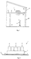
- 1 indicates a generator of simulated walking for phonometric measurements in the building industry.
- the generator 1 comprises a frame 2 provided with floor S rest means comprising, for example, feet 3, one or more hammers 4, in particular five and arranged in line, which are associated with the frame 2 and which are movably supported sliding in a direction substantially perpendicular to the ground S between a configuration that is raised in relation to the ground S and an impact configuration on the ground, and an automated actuating means 5 of the hammers 4 between their respective ascent and impact configurations and vice versa.
- floor S rest means comprising, for example, feet 3, one or more hammers 4, in particular five and arranged in line, which are associated with the frame 2 and which are movably supported sliding in a direction substantially perpendicular to the ground S between a configuration that is raised in relation to the ground S and an impact configuration on the ground, and an automated actuating means 5 of the hammers 4 between their respective ascent and impact configurations and vice versa.
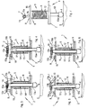
- the automated actuating means 5 is of the electromagnetic type and comprises at least one electromagnet 6 associated with a respective hammer 4, voltage supply means to the electromagnets 6 and an electronic circuit for the control and actuation of the electromagnets 6 and of the supply means; the supply means and the electronic circuit are not shown since they are known per se.
- the electronic circuit essentially comprises an electronic control unit, an on/off switch for each electromagnet 6, and a timer for each electromagnet 6 and is suitable for adjusting the time interval that elapses between the respective raised and impact configurations and a plurality of auxiliary timers suitable for adjusting the time intervals that elapse between the actuation of the single hammers 4 according to a preset sequence.
- Each electromagnet 6 comprises a tubular element 9 that is supported between a top plate 10 and a bottom plate 11, forming part of the frame 2, and which is arranged substantially perpendicular to the ground S; around the tubular element 9 at least an electric coil 12 is wound, comprising a wire, generally of copper, associated with the voltage supply means, and a core 13 in ferromagnetic material is slidingly housed in a direction that is substantially axial to the inside of the tubular element 9.
- a bush 14 can be interposed between the tubular element 9 and the core 13 .
- the tubular element 9, the frame 2 and, in particular, the first plate 10 and the second plate 11, and the bush 14 are made of non-magnetic material such as, for example, aluminium, brass, bronze, plastic or the like.
- the core 13 comprises a cylindrical bar that has a lower end 13a that points towards the ground S and which is joined with the respective hammer 4 and an opposite top end 13b; between the tubular element 9 or the bush 14 and the core 13 corresponding coupling play G is defined, whilst the bottom end 13a and the top end 13b extend outside the tubular element 9.
- the stabilisation means 7 is associated with the frame 2 and is arranged near the top end 13b of each core 13; in particular it may comprise an attraction element 15 of the respective core 13 that is substantially rod-shaped and is arranged above and transversely to the tubular element 9.
- the attraction element 15 has a first end 15a joined to a first support 16 associated with the top plate 10 and a second end 15b opposite the first, that is free and rests on a second support 17 associated with the top plate 10; the second support 17 may be covered with a layer of rubber. In an alternative embodiment, which is not shown, the second end 15b of the attraction element 15 can be joined to the second support 17.
- the attraction element 15 is usefully of the elastically deformable type, and it is made of ferromagnetic material and is advantageously arranged outside the tubular element 9 in which the respective core 13 is housed.
- the attraction element 15 comprises a spiral spring with close turns
- the first end 15a comprises in this case turns near the first support 16; however, alternative embodiments of the attraction element 15 and of the stabilising means 7 in general are not excluded.
- the recording means 8 of the height of the hammers 4 comprises, for example, adjusting means of the height of the first support 16 and/or the second support 17 in relation to the frame 2, in other words in relation to the top plate 10, suitable for varying the corresponding distance between the attraction element 15 and the top end 13b of the respective core 13.
- the adjusting means 8 may, for example, comprise a threaded stem defined below protruding from the bottom of the first support 16 and/or the second support 17 and which engages in a corresponding threaded hole defined in the top plate 10; nevertheless, different embodiments are not excluded.
- the cores 13, and the attraction elements 15 and the hammers 4 are made of ferromagnetic material such as for example iron or steel or the like.
- the control unit is suitable for controlling the supply means and the electromagnets 6 for sequential actuation of the hammers 4 at preset time intervals 1 between the respective raised and impact configurations and vice versa, the time interval also being presettable for the return of each hammer 4 between the respective impact or raised configuration.
- the generator 1 comprises usefully air-blowing means that is not shown that is arranged near each hammer 4 and which is suitable for sending an air jet at each hammer 4 in order to remove from it, and in particular from its impact surface with the ground S, any impurities, powders or fragments of the floor that may deposit themselves thereupon and which would invalidate the measurements.
- the blowing means comprises, for example, a ventilator (fan) located at each hammer 4.
- the blowing means comprises for example a central fan and an air-distribution conduit that is provided with an inlet port associated with the outlet of the central fan and with at least one outlet port located at each hammer 4.
- the invention operates as follows:
- the thus recalled core 13 slidingly oscillates along the tubular element 9; such oscillations are gradually lessened by the stabilisation means 7 that stop the core 13 in equilibrium in raised configuration.
- Stabilisation of the core 13 is due in particular to the force of attraction that the attraction element 15 exerts on the core 13 and on the dissipation through attrition that is generated by rubbing between the core 13 and the tubular element 9 or the bush 14; this rubbing is due to the fact that owing to the outside arrangement of the attraction element 15 in relation to the tubular element 9, the core 13 tilts in relation to the latter, thereby eliminating, at least in certain points, the corresponding play G.
- the attraction element 15 rotates around its first end 15a to then return to rest with its second end 15b on the second support 17.
- the attraction element 15, of the elastically deformable type flexes and arches upwards and then returns to its undeformed configuration.
- the blowing means keeps the impact surface of the hammers 4 clean.
- the phonometer F detects the noise that is generated in the chamber V2 after repeated and successive impact blows of the hammers 4 on the floor P1, which blows simulate the noise due to the fall of objects or footsteps of persons on the floor P1.
- the generator of simulated walking according to the invention in fact, owing to the use of automated means of the electromagnetic type for actuating hammers, eliminates the disturbance vibrations that are discharged on the floor, shocks and impacts between their various components being absent.
- the generator of simulated walking according to the invention thus enables the uncertainty of the phonometric data that are measurable with it to be reduced; it furthermore enables precise adjusting and setting of the fall height of the hammers, the time interval between the impact and the lifting of each hammer and the frequency of the pulses generated by the sequence of the impacts of the individual hammers.
- the automated actuating means of the electromagnetic type is subject to limited wear and enables maintenance and/or replacement of its components to be reduced and simplified.
Landscapes
- Engineering & Computer Science (AREA)
- Mechanical Engineering (AREA)
- Physics & Mathematics (AREA)
- Electromagnetism (AREA)
- Investigating Strength Of Materials By Application Of Mechanical Stress (AREA)
- Investigation Of Foundation Soil And Reinforcement Of Foundation Soil By Compacting Or Drainage (AREA)
Applications Claiming Priority (2)
| Application Number | Priority Date | Filing Date | Title |
|---|---|---|---|
| ITMO20030133 | 2003-05-09 | ||
| IT000133A ITMO20030133A1 (it) | 2003-05-09 | 2003-05-09 | Generatore di calpestio per misure fonometriche in edilizia. |
Publications (2)
| Publication Number | Publication Date |
|---|---|
| EP1475164A2 true EP1475164A2 (fr) | 2004-11-10 |
| EP1475164A3 EP1475164A3 (fr) | 2007-06-13 |
Family
ID=30012733
Family Applications (1)
| Application Number | Title | Priority Date | Filing Date |
|---|---|---|---|
| EP04011024A Withdrawn EP1475164A3 (fr) | 2003-05-09 | 2004-05-10 | Générateur de marche simulée pour mesures phonométriques dans l'industrie du bâtiment |
Country Status (2)
| Country | Link |
|---|---|
| EP (1) | EP1475164A3 (fr) |
| IT (1) | ITMO20030133A1 (fr) |
Cited By (3)
| Publication number | Priority date | Publication date | Assignee | Title |
|---|---|---|---|---|
| DE102006018165A1 (de) * | 2006-04-19 | 2007-10-25 | Kurz U. Fischer Gmbh, Beratende Ingenieure | Hammerwerk |
| ITVI20080232A1 (it) * | 2008-10-08 | 2010-04-09 | Zeta S N C Di Zattarin Ferdinand O E Zattarin G 2 | Generatore di calpestio |
| CN121231636A (zh) * | 2025-09-02 | 2025-12-30 | 江苏晟宇地板有限公司 | 一种基于智能传感的降噪地板检测装置 |
Family Cites Families (7)
| Publication number | Priority date | Publication date | Assignee | Title |
|---|---|---|---|---|
| DE1045045B (de) * | 1956-12-07 | 1958-11-27 | Dr Gerhard Metz | Perkussionsgeraet |
| US4019374A (en) * | 1975-07-24 | 1977-04-26 | Trw Inc. | Electromagnetic impulser for dynamically loading a structure |
| DE2617779C2 (de) * | 1976-04-23 | 1982-02-11 | Fraunhofer-Gesellschaft zur Förderung der angewandten Forschung e.V., 8000 München | Perkussionsinstrument für Diagnose- und Prüfzwecke |
| DE2946264C2 (de) * | 1979-11-16 | 1982-04-22 | Audi Nsu Auto Union Ag, 7107 Neckarsulm | Elektrodynamisches Impulsanregerät |
| JPS58100716A (ja) * | 1981-12-11 | 1983-06-15 | Hitachi Ltd | 振動検出装置の健全性確認方法及びその装置 |
| ES2033288T3 (es) * | 1986-12-11 | 1993-03-16 | Siemens Aktiengesellschaft | Instalacion para la calibracion de un sistema de supervision del sonido estructural. |
| DE4013663C2 (de) * | 1990-04-27 | 1999-10-28 | Kurz U Fischer Gmbh Beratende | System zu schalltechnischen Untersuchungen in Gebäuden |
-
2003
- 2003-05-09 IT IT000133A patent/ITMO20030133A1/it unknown
-
2004
- 2004-05-10 EP EP04011024A patent/EP1475164A3/fr not_active Withdrawn
Cited By (3)
| Publication number | Priority date | Publication date | Assignee | Title |
|---|---|---|---|---|
| DE102006018165A1 (de) * | 2006-04-19 | 2007-10-25 | Kurz U. Fischer Gmbh, Beratende Ingenieure | Hammerwerk |
| ITVI20080232A1 (it) * | 2008-10-08 | 2010-04-09 | Zeta S N C Di Zattarin Ferdinand O E Zattarin G 2 | Generatore di calpestio |
| CN121231636A (zh) * | 2025-09-02 | 2025-12-30 | 江苏晟宇地板有限公司 | 一种基于智能传感的降噪地板检测装置 |
Also Published As
| Publication number | Publication date |
|---|---|
| ITMO20030133A1 (it) | 2004-11-10 |
| ITMO20030133A0 (it) | 2003-05-09 |
| EP1475164A3 (fr) | 2007-06-13 |
Similar Documents
| Publication | Publication Date | Title |
|---|---|---|
| JP5705440B2 (ja) | 発電装置、発電システム、構造物、及び発電装置の設計方法 | |
| EP1475164A2 (fr) | Générateur de marche simulée pour mesures phonométriques dans l'industrie du bâtiment | |
| US4204678A (en) | Tennis playing apparatus | |
| JP5503264B2 (ja) | 発電装置 | |
| JP2013048709A (ja) | 遊技機 | |
| JP2019511082A (ja) | 車両用操作ユニット | |
| US11460086B2 (en) | Active inertial damper system and method | |
| JP2013048708A (ja) | 遊技機 | |
| KR101584700B1 (ko) | 능동형 제진장치 | |
| US5627336A (en) | Percussion instrument having an electromagnetic sensor | |
| WO2005001810A1 (fr) | Dispositif de mesure de resonance et/ou de vibration | |
| JP2003337079A (ja) | 動電式振動試験装置 | |
| US4543835A (en) | Dry flow sensor with a linear force transducer | |
| US3552748A (en) | Apparatus for holding a pole vaulting bar | |
| WO2007139050A1 (fr) | Dispositif de vibration | |
| WO2000054248A1 (fr) | Piano muni d'un mecanisme a touches et a marteaux comprenant des aimants permanents | |
| KR20090016648A (ko) | 진동감쇄 기구를 가진 스페이서 | |
| JP5589336B2 (ja) | 鍵盤装置 | |
| US318472A (en) | Chaeles hekzel | |
| US694511A (en) | Mounting of electric bells. | |
| JP2940009B2 (ja) | 振動検出器 | |
| US2595811A (en) | Electric switch for games | |
| US2770994A (en) | Musical instruments with capacitative pickup | |
| JP3423044B2 (ja) | 組合せ秤における分散フィーダの制御装置 | |
| CN1505753A (zh) | 确定表面刚度和阻尼值的方法和设备 |
Legal Events
| Date | Code | Title | Description |
|---|---|---|---|
| PUAI | Public reference made under article 153(3) epc to a published international application that has entered the european phase |
Free format text: ORIGINAL CODE: 0009012 |
|
| AK | Designated contracting states |
Kind code of ref document: A2 Designated state(s): AT BE BG CH CY CZ DE DK EE ES FI FR GB GR HU IE IT LI LU MC NL PL PT RO SE SI SK TR |
|
| AX | Request for extension of the european patent |
Extension state: AL HR LT LV MK |
|
| PUAL | Search report despatched |
Free format text: ORIGINAL CODE: 0009013 |
|
| AK | Designated contracting states |
Kind code of ref document: A3 Designated state(s): AT BE BG CH CY CZ DE DK EE ES FI FR GB GR HU IE IT LI LU MC NL PL PT RO SE SI SK TR |
|
| AX | Request for extension of the european patent |
Extension state: AL HR LT LV MK |
|
| AKX | Designation fees paid | ||
| REG | Reference to a national code |
Ref country code: DE Ref legal event code: 8566 |
|
| STAA | Information on the status of an ep patent application or granted ep patent |
Free format text: STATUS: THE APPLICATION IS DEEMED TO BE WITHDRAWN |
|
| 18D | Application deemed to be withdrawn |
Effective date: 20071214 |