EP1475183B1 - Actionneur linéaire avec un moteur électrique et un système de blocage montés sur un chariot - Google Patents
Actionneur linéaire avec un moteur électrique et un système de blocage montés sur un chariot Download PDFInfo
- Publication number
- EP1475183B1 EP1475183B1 EP04009631A EP04009631A EP1475183B1 EP 1475183 B1 EP1475183 B1 EP 1475183B1 EP 04009631 A EP04009631 A EP 04009631A EP 04009631 A EP04009631 A EP 04009631A EP 1475183 B1 EP1475183 B1 EP 1475183B1
- Authority
- EP
- European Patent Office
- Prior art keywords
- carriage
- motor
- adjusting device
- worm gear
- guide
- Prior art date
- Legal status (The legal status is an assumption and is not a legal conclusion. Google has not performed a legal analysis and makes no representation as to the accuracy of the status listed.)
- Expired - Lifetime
Links
- 230000005540 biological transmission Effects 0.000 claims description 4
- 230000007246 mechanism Effects 0.000 claims description 4
- 230000004913 activation Effects 0.000 claims 1
- 230000000903 blocking effect Effects 0.000 abstract description 6
- 238000006073 displacement reaction Methods 0.000 description 10
- 239000002904 solvent Substances 0.000 description 4
- 230000008901 benefit Effects 0.000 description 3
- 238000004806 packaging method and process Methods 0.000 description 3
- 230000010354 integration Effects 0.000 description 2
- 230000008859 change Effects 0.000 description 1
- 230000008878 coupling Effects 0.000 description 1
- 238000010168 coupling process Methods 0.000 description 1
- 238000005859 coupling reaction Methods 0.000 description 1
- 238000000605 extraction Methods 0.000 description 1
- 230000005764 inhibitory process Effects 0.000 description 1
- 238000011089 mechanical engineering Methods 0.000 description 1
- 230000003287 optical effect Effects 0.000 description 1
- 238000005192 partition Methods 0.000 description 1
- 230000009467 reduction Effects 0.000 description 1
Images



Classifications
-
- B—PERFORMING OPERATIONS; TRANSPORTING
- B23—MACHINE TOOLS; METAL-WORKING NOT OTHERWISE PROVIDED FOR
- B23Q—DETAILS, COMPONENTS, OR ACCESSORIES FOR MACHINE TOOLS, e.g. ARRANGEMENTS FOR COPYING OR CONTROLLING; MACHINE TOOLS IN GENERAL CHARACTERISED BY THE CONSTRUCTION OF PARTICULAR DETAILS OR COMPONENTS; COMBINATIONS OR ASSOCIATIONS OF METAL-WORKING MACHINES, NOT DIRECTED TO A PARTICULAR RESULT
- B23Q1/00—Members which are comprised in the general build-up of a form of machine, particularly relatively large fixed members
- B23Q1/25—Movable or adjustable work or tool supports
- B23Q1/26—Movable or adjustable work or tool supports characterised by constructional features relating to the co-operation of relatively movable members; Means for preventing relative movement of such members
- B23Q1/28—Means for securing sliding members in any desired position
-
- B—PERFORMING OPERATIONS; TRANSPORTING
- B23—MACHINE TOOLS; METAL-WORKING NOT OTHERWISE PROVIDED FOR
- B23Q—DETAILS, COMPONENTS, OR ACCESSORIES FOR MACHINE TOOLS, e.g. ARRANGEMENTS FOR COPYING OR CONTROLLING; MACHINE TOOLS IN GENERAL CHARACTERISED BY THE CONSTRUCTION OF PARTICULAR DETAILS OR COMPONENTS; COMBINATIONS OR ASSOCIATIONS OF METAL-WORKING MACHINES, NOT DIRECTED TO A PARTICULAR RESULT
- B23Q1/00—Members which are comprised in the general build-up of a form of machine, particularly relatively large fixed members
- B23Q1/25—Movable or adjustable work or tool supports
- B23Q1/44—Movable or adjustable work or tool supports using particular mechanisms
- B23Q1/56—Movable or adjustable work or tool supports using particular mechanisms with sliding pairs only, the sliding pairs being the first two elements of the mechanism
- B23Q1/58—Movable or adjustable work or tool supports using particular mechanisms with sliding pairs only, the sliding pairs being the first two elements of the mechanism a single sliding pair
-
- B—PERFORMING OPERATIONS; TRANSPORTING
- B23—MACHINE TOOLS; METAL-WORKING NOT OTHERWISE PROVIDED FOR
- B23Q—DETAILS, COMPONENTS, OR ACCESSORIES FOR MACHINE TOOLS, e.g. ARRANGEMENTS FOR COPYING OR CONTROLLING; MACHINE TOOLS IN GENERAL CHARACTERISED BY THE CONSTRUCTION OF PARTICULAR DETAILS OR COMPONENTS; COMBINATIONS OR ASSOCIATIONS OF METAL-WORKING MACHINES, NOT DIRECTED TO A PARTICULAR RESULT
- B23Q5/00—Driving or feeding mechanisms; Control arrangements therefor
- B23Q5/22—Feeding members carrying tools or work
- B23Q5/34—Feeding other members supporting tools or work, e.g. saddles, tool-slides, through mechanical transmission
- B23Q5/38—Feeding other members supporting tools or work, e.g. saddles, tool-slides, through mechanical transmission feeding continuously
- B23Q5/385—Feeding other members supporting tools or work, e.g. saddles, tool-slides, through mechanical transmission feeding continuously using a gear and rack mechanism or a friction wheel co-operating with a rail
-
- Y—GENERAL TAGGING OF NEW TECHNOLOGICAL DEVELOPMENTS; GENERAL TAGGING OF CROSS-SECTIONAL TECHNOLOGIES SPANNING OVER SEVERAL SECTIONS OF THE IPC; TECHNICAL SUBJECTS COVERED BY FORMER USPC CROSS-REFERENCE ART COLLECTIONS [XRACs] AND DIGESTS
- Y10—TECHNICAL SUBJECTS COVERED BY FORMER USPC
- Y10T—TECHNICAL SUBJECTS COVERED BY FORMER US CLASSIFICATION
- Y10T74/00—Machine element or mechanism
- Y10T74/18—Mechanical movements
- Y10T74/18056—Rotary to or from reciprocating or oscillating
- Y10T74/18072—Reciprocating carriage motions
-
- Y—GENERAL TAGGING OF NEW TECHNOLOGICAL DEVELOPMENTS; GENERAL TAGGING OF CROSS-SECTIONAL TECHNOLOGIES SPANNING OVER SEVERAL SECTIONS OF THE IPC; TECHNICAL SUBJECTS COVERED BY FORMER USPC CROSS-REFERENCE ART COLLECTIONS [XRACs] AND DIGESTS
- Y10—TECHNICAL SUBJECTS COVERED BY FORMER USPC
- Y10T—TECHNICAL SUBJECTS COVERED BY FORMER US CLASSIFICATION
- Y10T74/00—Machine element or mechanism
- Y10T74/18—Mechanical movements
- Y10T74/18056—Rotary to or from reciprocating or oscillating
- Y10T74/18088—Rack and pinion type
-
- Y—GENERAL TAGGING OF NEW TECHNOLOGICAL DEVELOPMENTS; GENERAL TAGGING OF CROSS-SECTIONAL TECHNOLOGIES SPANNING OVER SEVERAL SECTIONS OF THE IPC; TECHNICAL SUBJECTS COVERED BY FORMER USPC CROSS-REFERENCE ART COLLECTIONS [XRACs] AND DIGESTS
- Y10—TECHNICAL SUBJECTS COVERED BY FORMER USPC
- Y10T—TECHNICAL SUBJECTS COVERED BY FORMER US CLASSIFICATION
- Y10T74/00—Machine element or mechanism
- Y10T74/18—Mechanical movements
- Y10T74/18056—Rotary to or from reciprocating or oscillating
- Y10T74/18088—Rack and pinion type
- Y10T74/18104—Shiftable pinion
-
- Y—GENERAL TAGGING OF NEW TECHNOLOGICAL DEVELOPMENTS; GENERAL TAGGING OF CROSS-SECTIONAL TECHNOLOGIES SPANNING OVER SEVERAL SECTIONS OF THE IPC; TECHNICAL SUBJECTS COVERED BY FORMER USPC CROSS-REFERENCE ART COLLECTIONS [XRACs] AND DIGESTS
- Y10—TECHNICAL SUBJECTS COVERED BY FORMER USPC
- Y10T—TECHNICAL SUBJECTS COVERED BY FORMER US CLASSIFICATION
- Y10T74/00—Machine element or mechanism
- Y10T74/18—Mechanical movements
- Y10T74/18568—Reciprocating or oscillating to or from alternating rotary
- Y10T74/18792—Reciprocating or oscillating to or from alternating rotary including worm
-
- Y—GENERAL TAGGING OF NEW TECHNOLOGICAL DEVELOPMENTS; GENERAL TAGGING OF CROSS-SECTIONAL TECHNOLOGIES SPANNING OVER SEVERAL SECTIONS OF THE IPC; TECHNICAL SUBJECTS COVERED BY FORMER USPC CROSS-REFERENCE ART COLLECTIONS [XRACs] AND DIGESTS
- Y10—TECHNICAL SUBJECTS COVERED BY FORMER USPC
- Y10T—TECHNICAL SUBJECTS COVERED BY FORMER US CLASSIFICATION
- Y10T74/00—Machine element or mechanism
- Y10T74/19—Gearing
- Y10T74/19637—Gearing with brake means for gearing
-
- Y—GENERAL TAGGING OF NEW TECHNOLOGICAL DEVELOPMENTS; GENERAL TAGGING OF CROSS-SECTIONAL TECHNOLOGIES SPANNING OVER SEVERAL SECTIONS OF THE IPC; TECHNICAL SUBJECTS COVERED BY FORMER USPC CROSS-REFERENCE ART COLLECTIONS [XRACs] AND DIGESTS
- Y10—TECHNICAL SUBJECTS COVERED BY FORMER USPC
- Y10T—TECHNICAL SUBJECTS COVERED BY FORMER US CLASSIFICATION
- Y10T74/00—Machine element or mechanism
- Y10T74/19—Gearing
- Y10T74/19642—Directly cooperating gears
- Y10T74/19698—Spiral
- Y10T74/19819—Driven rack or shaft
Definitions
- the invention relates to an adjusting device according to the preamble of Claim 1.
- Such adjusting devices are known from the mechanical engineering industry and For example, they are used in packaging machines, e.g. the Machine to be able to change from one packaging size to another. there Be about the adjustment, for example, stops or other Machine parts adjusted and repositioned according to the new task.
- the adjustment is either by hand made by a tool or motor driven.
- a locking device provided to the adjusted carriage of the To fix adjusting in its new position.
- This locking device usually consists of a locking screw or the like.
- To the to set desired positions without major adjustments can, are provided to the adjustment counters, the For example, count the revolutions of a spindle of the adjustment.
- From GB 2 142 410 A is an adjusting device according to the preamble of Claim 1 known.
- the adjusting device with a carriage, with at least a guide member on which the carriage is slidably mounted, with a Verschiebevorrichung for moving the carriage and with a locking device for detecting the slid shifted to a desired position an electric drive for the adjusting device, wherein the drive in the Carriage is integrated and the locking device has locking means, the at Standstill of the motor blocking a sliding of the carriage and on startup automatically release the engine.
- the locking means comprise a worm wheel of a driving gear, wherein the worm wheel for moving the carriage engages in a provided in the guide element tooth row.
- the Locking means on a clamping element with which the worm wheel against the row of teeth is clamped storable, and there is a solvent provided with the on the worm wheel clamping force against the operation of the engine automatically against the clamping force of the clamping element is releasable.
- the main advantage is that no separate locking device necessary is and should be operated, because the adjusting device according to the invention blocks automatically when the engine stops and releases when the engine starts up Motors automatically. This can be handles and thus time when moving the Machine can be saved.
- Another advantage is the integration of the motor in the carriage, because can be saved considerable space, which is in today's machines, which are becoming ever more compact is of great benefit. Also, the invention Training the locking device contributes significantly to the space savings.
- the locking device has a locking means and the locking means a Worm gear of a driving gear can include the property of Self-locking be exploited.
- worm gears are play and noise.
- the guide element for example a guide rod, a row of teeth has, in which engages the worm wheel for moving the carriage,
- the guide rod can be used to guide and propel the carriage be used.
- the locking means a Has clamping element with which the worm wheel clamped against the row of teeth is storable.
- a solvent is provided with which the on the worm wheel clamping force against the operation of the engine automatically against the clamping force of the clamping element is releasable. This is the simplest way Blocking of the sled detachable.
- the clamping means is a leaf spring on an axis of the worm wheel acts and the worm wheel on the row of teeth suppressed.
- the guide lever is symmetrical, so that a release the locking device both left and right of the engine he follows.
- the position of the carriage can be determined exactly and be output via signals.
- the position signals can be fed to a controller that automatically adjusts without any Handles possible.
- the position signals can be fed to the controller, which can perform an adjustment automatically.
- the position data can for example, be programmed into the controller or storage media be entered.
- An adjustment of a complete machine, e.g. a packaging machine, can then take only a few minutes, what so far a half to an hour was necessary.
- the engine is centered in the carriage and drives over
- the gearbox has two worm wheels that move each into a row of teeth engage the guide rods.
- Locking and solvent are provided on both worm wheels.
- a Connection for a tool such as Allen key, provided to so that the displacement device can be operated manually.
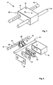
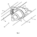
- An adjusting device 10 shown in the drawing has one on two Guide elements 12 and 14 slidably mounted carriage 16.
- the Guide elements 12 and 14 are formed as guide rods.
- Of the Guide carriage includes a housing 18 with housing cover 20, of the Guide rods 12 and 14 are interspersed.
- a displacement device 22 is arranged, by means of which the Carriage 16 can be moved on the guide rods 12 and 14.
- the Displacement device 22 has to drive an electric motor 24 with a Gear 26 on.
- the gear 26 is symmetrical and engages on both sides in each case a row of teeth 28 and 30, each in one of the guide rods 12th or 14 are provided.
- Each of the two sides of the transmission 26 consists of a first gear 32.1 and 32.2, driven by a drive pinion 34 become.
- the first gear 32.1 or 32.2 drives a worm wheel 36.1 or 36.2, which in turn engages with its worm in the respective row of teeth 28 and 30, so that via the motor 24, the drive pinion 34, the first gears 32.1 and 32.2 and the worm wheels 36.1 and 36.2 depending on the direction of rotation of the Motors 24 a forward or reverse of the carriage 16 along the guide rods 12 and 14 is effected.
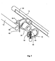
- the adjusting device 10 further comprises a locking device 38, as shown in Fig. 8.
- the locking device 38 comprises a Leaf spring 40, a guide lever 42 and first and second return springs 44 and 46.
- the leaf spring 40 serves as a clamping means to the worm wheel 36.1 against the To press row 28 of the guide rod 12.
- the leaf spring 40 forms together with the worm wheel 36.1 a locking means with which the Self-locking between worm wheel 36.1 and row of teeth 28 is reinforced and a blockage of the carriage 16 takes place.
- a guide portion 52 connects, the one Guide groove 54 has.
- the guide groove 54 is a worm shaft 56 of the Worm wheel 36.1 held.
- Motor housing 25 rotate at an angle about its axis of rotation 58, due a certain torque that the motor 24 must apply to the To drive gear 26.
- the motor housing 25 is rotatable in the housing 18 stored.
- the motor housing 25 is twisted, the twisted Guide lever 42 in the same degree. Since the worm wheel 56 in the Guide groove 54 is guided and the guide groove 54 is formed in such a manner (Fig.
- the locking device 38 described forms a closed Control circuit, since the motor 24 apply a torque against the blocking force must and the torque resulting from the twist but turn is exploited to solve the blockage.
- the blocking is so at startup of the Motors 24 automatically solved and remain solved as long as the engine 24 is running. at Standstill of the engine, the blockage is reactivated due to the spring forces.
- the displacement device 22 is received in the housing 18 and in Direction to the lid 20 with a housing intermediate wall 70 held.
- circuit board 72nd arranged between housing intermediate wall 70 and cover 20 .
- the displacement device has a non-illustrated Multi-turn encoder on, for example, the angular position and revolutions of the second worm wheel 36.2 can measure.
- the necessary Components such as optical and / or magnetic Abtastvoraumen and possibly.
- Reduction gear as they are known from multi-turn encoders and in the Drawing are not shown in detail, can on the circuit board 72 and at the Housing partition wall 70 may be arranged.
- 16 are possible connections 74 for an electric on the carriage Supply and extraction and coupling of signals, in particular a Interface, provided.
- the locking device could be provided on both sides, ie on both worm wheels 36.1 and 36.2.
- the adjusting device can be actuated manually
Landscapes
- Engineering & Computer Science (AREA)
- Mechanical Engineering (AREA)
- Transmission Devices (AREA)
- Gear Transmission (AREA)
- Supporting Of Heads In Record-Carrier Devices (AREA)
- Moving Of Heads (AREA)
- Lock And Its Accessories (AREA)
Claims (11)
- Dispositif de réglage comportant un chariot (16), au moins un élément de guidage (12 ; 14) sur lequel le chariot (16) est monté de façon à pouvoir se déplacer, un dispositif de déplacement (22) pour le déplacement du chariot (16), un dispositif de blocage (38) pour bloquer le chariot (16) déplacé dans une position souhaitée, le dispositif de déplacement (22) comportant un moteur électrique (24) qui est intégré dans le chariot (16), et le dispositif de blocage (38) comportant des moyens de blocage, qui bloquent un déplacement du chariot (16) lors de l'arrêt du moteur (24) et qui se dissocient automatiquement lors du démarrage du moteur (24), les moyens de blocage comprenant une roue à denture hélicoïdale (36.1) d'une transmission d'entraínement, et la roue à denture hélicoïdale (36.1) s'engageant pour le déplacement du chariot (16) dans une rangée de dents (28) prévue dans l'élément de guidage (12), caractérisé en ce que le moyen de blocage comporte en outre un élément de serrage (40), avec lequel la roue à denture hélicoïdale (36.1) peut être montée en étant serrée contre la rangée de dents (28), et en ce qu'il est prévu un moyen de dissociation (42), avec lequel la force de serrage exercée sur la roue à denture hélicoïdale (36.1) peut être dissociée automatiquement en s'opposant à la force de serrage de l'élément de serrage (40) lors du fonctionnement du moteur (24).
- Dispositif de réglage selon la revendication 1, caractérisé en ce que le moyen de serrage (40) est un ressort à lame (40) qui agit sur un arbre de roue à denture hélicoïdale (36.1).
- Dispositif de réglage selon l'une des revendications précédentes, caractérisé en ce que le moyen de dissociation (42) est un levier de guidage (42) relié solidairement en rotation au moteur (24), qui guide la position de la roue à denture hélicoïdale (36.1) en fonction de la position angulaire du carter (25) de moteur.
- Dispositif de réglage selon la revendication 3, caractérisé en ce que le levier de guidage (42) est agencé de façon symétrique.
- Dispositif de réglage selon l'une des revendications, précédentes, caractérisé en ce que le dispositif de déplacement avec le moteur comporte un indicateur de rotations, de préférence un indicateur de rotations multitours.
- Dispositif de réglage selon l'une des revendications précédentes, caractérisé en ce que la position angulaire et/ou des rotations d'au moins un élément de transmission entraíné, de préférence de la roue à denture hélicoïdale, peuvent être déterminées avec l'indicateur de rotations.
- Dispositif de réglage selon l'une des revendications précédentes, caractérisé en ce que deux barres de guidage (12 et 14) sont prévues en tant qu'éléments de guidage (12, 14), en ce que le moteur (24) est disposé au milieu du chariot (16), et en ce que la transmission (26) entraíne deux roues à denture hélicoïdale (36.1 et 36.2) qui, pour le déplacement, s'engagent respectivement dans une rangée de dents (28 ou 30) des barres de guidage (12, 14).
- Dispositif de réglage selon la revendication 7, caractérisé en ce que des moyens de blocage et de dissociation sont prévus sur les deux roues à denture hélicoïdale.
- Dispositif de réglage selon l'une des revendications précédentes, caractérisé par une interface (74) pour le raccordement d'une commande pour le dispositif de déplacement (22).
- Dispositif de réglage selon l'une des revendications précédentes, caractérisé par des éléments de commande pouvant être actionnés manuellement pour la commutation du moteur.
- Dispositif de réglage selon l'une des revendications précédentes, caractérisé par un raccordement pour un outil, tel que par exemple une clé à six pans creux, pour l'actionnement manuel du dispositif de déplacement.
Applications Claiming Priority (2)
| Application Number | Priority Date | Filing Date | Title |
|---|---|---|---|
| DE10320271A DE10320271A1 (de) | 2003-05-07 | 2003-05-07 | Verstelleinrichtung |
| DE10320271 | 2003-05-07 |
Publications (2)
| Publication Number | Publication Date |
|---|---|
| EP1475183A1 EP1475183A1 (fr) | 2004-11-10 |
| EP1475183B1 true EP1475183B1 (fr) | 2005-11-23 |
Family
ID=32981256
Family Applications (1)
| Application Number | Title | Priority Date | Filing Date |
|---|---|---|---|
| EP04009631A Expired - Lifetime EP1475183B1 (fr) | 2003-05-07 | 2004-04-23 | Actionneur linéaire avec un moteur électrique et un système de blocage montés sur un chariot |
Country Status (4)
| Country | Link |
|---|---|
| US (1) | US7222550B2 (fr) |
| EP (1) | EP1475183B1 (fr) |
| AT (1) | ATE310606T1 (fr) |
| DE (2) | DE10320271A1 (fr) |
Families Citing this family (4)
| Publication number | Priority date | Publication date | Assignee | Title |
|---|---|---|---|---|
| CN201478928U (zh) * | 2009-09-01 | 2010-05-19 | 中山大洋电机股份有限公司 | 一种转轴的制动装置及其应用的齿轮减速电机系统 |
| US9145956B2 (en) | 2013-01-25 | 2015-09-29 | Gustomsc Resources B.V. | Torque sharing drive and torque sharing process |
| CN103252657B (zh) * | 2013-05-29 | 2016-05-18 | 江苏金飞达电动工具有限公司 | 一种偏心锁紧装置 |
| US9531237B2 (en) | 2013-12-19 | 2016-12-27 | Gustomsc Resources B.V. | Dual rack output pinion drive |
Family Cites Families (18)
| Publication number | Priority date | Publication date | Assignee | Title |
|---|---|---|---|---|
| US1283142A (en) * | 1917-12-14 | 1918-10-29 | Warren F Fraser | Mechanical movement. |
| US2125543A (en) * | 1937-06-28 | 1938-08-02 | Aresee Company Inc | Window lock |
| GB1185800A (en) * | 1968-12-12 | 1970-03-25 | Cam Gears Ltd | Improvements in or relating to Rack and Pinion Assemblies |
| GB1585412A (en) * | 1977-03-03 | 1981-03-04 | Twiflex Couplings | Brake actuating mechanisms |
| US4282776A (en) * | 1979-03-29 | 1981-08-11 | Eller Fritz D | Overload protection for transmission system with planetary-gear train |
| GB2142410A (en) * | 1983-07-01 | 1985-01-16 | Ciniglio A J | Improvements in or relating to linear actuators |
| DK153008C (da) * | 1985-06-26 | 1988-10-24 | Dansk Gartneri Tek As | Overbelastningssikring med tandhjulsudveksling. |
| GB8529892D0 (en) * | 1985-12-04 | 1986-01-15 | Martock Design Ltd | Micro-positioning actuators |
| JPH06170676A (ja) * | 1992-12-04 | 1994-06-21 | Toshiba Mach Co Ltd | 工作機械の軸回転駆動装置 |
| US5546826A (en) * | 1994-01-13 | 1996-08-20 | Yanagisawa; Ken | Drive system |
| EP0873963A1 (fr) * | 1997-04-25 | 1998-10-28 | Inventio Ag | Entraínement linéaire pour un dispositif de transport |
| DE19744695A1 (de) * | 1997-08-01 | 1998-11-26 | Bosch Gmbh Robert | Stelleinrichtung, insbesondere für eine Kraftfahrzeug-Reibungskupplung |
| JP4079512B2 (ja) * | 1998-05-25 | 2008-04-23 | デルタ工業株式会社 | 車両用シートの減速装置 |
| US6216394B1 (en) * | 1998-09-21 | 2001-04-17 | Paul J. Fenelon | Window lift mechanism |
| DE19847016A1 (de) * | 1998-10-13 | 2000-04-20 | Bosch Gmbh Robert | Vorrichtung zum Bewegen eines Teils, insbesondere in einem Kraftfahrzeug, mit einem Verstellmechanismus |
| DE29911554U1 (de) * | 1999-07-02 | 1999-09-23 | Baumeister Karlheinz | Vorrichtung zum linearen Verstellen zweier Bauteile |
| US6390230B1 (en) * | 1999-10-06 | 2002-05-21 | Honda Giken Kogyo Kabushiki Kaisha | Electric power steering apparatus |
| EP1355074A1 (fr) * | 2002-04-18 | 2003-10-22 | Güdel AG Antriebs- und Lineartechnik | Entrainement linéaire |
-
2003
- 2003-05-07 DE DE10320271A patent/DE10320271A1/de not_active Withdrawn
-
2004
- 2004-04-23 AT AT04009631T patent/ATE310606T1/de not_active IP Right Cessation
- 2004-04-23 DE DE502004000139T patent/DE502004000139D1/de not_active Expired - Lifetime
- 2004-04-23 EP EP04009631A patent/EP1475183B1/fr not_active Expired - Lifetime
- 2004-05-05 US US10/839,983 patent/US7222550B2/en not_active Expired - Fee Related
Also Published As
| Publication number | Publication date |
|---|---|
| DE502004000139D1 (de) | 2005-12-29 |
| EP1475183A1 (fr) | 2004-11-10 |
| US7222550B2 (en) | 2007-05-29 |
| ATE310606T1 (de) | 2005-12-15 |
| DE10320271A1 (de) | 2004-12-02 |
| US20050000308A1 (en) | 2005-01-06 |
Similar Documents
| Publication | Publication Date | Title |
|---|---|---|
| EP1893456B1 (fr) | Dispositif de verrouillage destine a un arbre de direction presentant une position d'arret selectionnable en cas de mouvement du dispositif de boulon de blocage en direction de la position terminale de liberation | |
| EP2964508B1 (fr) | Dispositif de limitation de l'effort de direction dans une direction assistée électrique | |
| WO2003086836A2 (fr) | Engrenage de direction sans jeu | |
| EP2736150A2 (fr) | Entraînement linéaire | |
| DE3309249A1 (de) | Vorrichtung zum verschieben eines schlittens od.dgl. an einem bett od.dgl. | |
| EP1619398A1 (fr) | Dispositif de positionnement, en particulier frein de stationnement d'un véhicule | |
| EP1475183B1 (fr) | Actionneur linéaire avec un moteur électrique et un système de blocage montés sur un chariot | |
| EP1870617B1 (fr) | Dispositif d'actionnement pour une transmission d'un véhicule | |
| DE102013107378A1 (de) | Antriebsvorrichtung | |
| EP1768009A1 (fr) | Actuateur rotatif | |
| DE202014100866U1 (de) | Einachsiger Linearantrieb | |
| DE3441364C2 (fr) | ||
| WO2009015995A1 (fr) | Actionneur de boîte de vitesses pour actionner un dispositif de commutation d'une boîte de vitesses | |
| EP2487393A1 (fr) | Vanne de serrage | |
| DE1962663C3 (de) | Vorrichtung zur Herstellung von mit Innengewinde versehenen Spritzlingen in Spritzgießformen | |
| DE4005181C1 (en) | Machine tool work spindle drive - has angularly adjustable motor with spur gearing controlled via pawl | |
| DE20214764U1 (de) | Schalteinrichtung zur Ansteuerung wenigstens zweier Motoren | |
| DE102006060992B3 (de) | Motorisch betätigte Verriegelungsvorrichtung | |
| EP0438438A1 (fr) | Dispositif pour diriger les roues arriere de vehicules a roues avant et arriere orientables. | |
| DE3424515C2 (fr) | ||
| DE202005001208U1 (de) | Elektromotorische Antriebsanordnung | |
| DE19652905C2 (de) | Antrieb für einen Tisch einer an einer Basis befestigten Transport- oder Hubeinrichtung | |
| DE102004010805A1 (de) | Verstellbare Lenksäule | |
| DE3826863A1 (de) | Vorrichtung zum positionieren eines werkstuecks oder einer hilfsvorrichtung in zwei koordinaten mit hoher wegaufloesung fuer nc-fraesmaschinen | |
| DE2442622B1 (de) | Motor- und handverstellbares schraubgetriebe |
Legal Events
| Date | Code | Title | Description |
|---|---|---|---|
| PUAI | Public reference made under article 153(3) epc to a published international application that has entered the european phase |
Free format text: ORIGINAL CODE: 0009012 |
|
| AK | Designated contracting states |
Kind code of ref document: A1 Designated state(s): AT BE BG CH CY CZ DE DK EE ES FI FR GB GR HU IE IT LI LU MC NL PL PT RO SE SI SK TR |
|
| AX | Request for extension of the european patent |
Extension state: AL HR LT LV MK |
|
| 17P | Request for examination filed |
Effective date: 20050112 |
|
| 17Q | First examination report despatched |
Effective date: 20050215 |
|
| GRAP | Despatch of communication of intention to grant a patent |
Free format text: ORIGINAL CODE: EPIDOSNIGR1 |
|
| AKX | Designation fees paid |
Designated state(s): AT BE BG CH CY CZ DE DK EE ES FI FR GB GR HU IE IT LI LU MC NL PL PT RO SE SI SK TR |
|
| GRAS | Grant fee paid |
Free format text: ORIGINAL CODE: EPIDOSNIGR3 |
|
| GRAA | (expected) grant |
Free format text: ORIGINAL CODE: 0009210 |
|
| AK | Designated contracting states |
Kind code of ref document: B1 Designated state(s): AT BE BG CH CY CZ DE DK EE ES FI FR GB GR HU IE IT LI LU MC NL PL PT RO SE SI SK TR |
|
| PG25 | Lapsed in a contracting state [announced via postgrant information from national office to epo] |
Ref country code: NL Free format text: LAPSE BECAUSE OF FAILURE TO SUBMIT A TRANSLATION OF THE DESCRIPTION OR TO PAY THE FEE WITHIN THE PRESCRIBED TIME-LIMIT Effective date: 20051123 Ref country code: IE Free format text: LAPSE BECAUSE OF FAILURE TO SUBMIT A TRANSLATION OF THE DESCRIPTION OR TO PAY THE FEE WITHIN THE PRESCRIBED TIME-LIMIT Effective date: 20051123 Ref country code: CZ Free format text: LAPSE BECAUSE OF FAILURE TO SUBMIT A TRANSLATION OF THE DESCRIPTION OR TO PAY THE FEE WITHIN THE PRESCRIBED TIME-LIMIT Effective date: 20051123 Ref country code: PL Free format text: LAPSE BECAUSE OF FAILURE TO SUBMIT A TRANSLATION OF THE DESCRIPTION OR TO PAY THE FEE WITHIN THE PRESCRIBED TIME-LIMIT Effective date: 20051123 Ref country code: GB Free format text: LAPSE BECAUSE OF FAILURE TO SUBMIT A TRANSLATION OF THE DESCRIPTION OR TO PAY THE FEE WITHIN THE PRESCRIBED TIME-LIMIT Effective date: 20051123 Ref country code: SK Free format text: LAPSE BECAUSE OF FAILURE TO SUBMIT A TRANSLATION OF THE DESCRIPTION OR TO PAY THE FEE WITHIN THE PRESCRIBED TIME-LIMIT Effective date: 20051123 Ref country code: FI Free format text: LAPSE BECAUSE OF FAILURE TO SUBMIT A TRANSLATION OF THE DESCRIPTION OR TO PAY THE FEE WITHIN THE PRESCRIBED TIME-LIMIT Effective date: 20051123 Ref country code: SI Free format text: LAPSE BECAUSE OF FAILURE TO SUBMIT A TRANSLATION OF THE DESCRIPTION OR TO PAY THE FEE WITHIN THE PRESCRIBED TIME-LIMIT Effective date: 20051123 Ref country code: RO Free format text: LAPSE BECAUSE OF FAILURE TO SUBMIT A TRANSLATION OF THE DESCRIPTION OR TO PAY THE FEE WITHIN THE PRESCRIBED TIME-LIMIT Effective date: 20051123 |
|
| REG | Reference to a national code |
Ref country code: GB Ref legal event code: FG4D Free format text: NOT ENGLISH |
|
| REG | Reference to a national code |
Ref country code: CH Ref legal event code: EP |
|
| REF | Corresponds to: |
Ref document number: 502004000139 Country of ref document: DE Date of ref document: 20051229 Kind code of ref document: P |
|
| REG | Reference to a national code |
Ref country code: IE Ref legal event code: FG4D Free format text: LANGUAGE OF EP DOCUMENT: GERMAN |
|
| PG25 | Lapsed in a contracting state [announced via postgrant information from national office to epo] |
Ref country code: DK Free format text: LAPSE BECAUSE OF FAILURE TO SUBMIT A TRANSLATION OF THE DESCRIPTION OR TO PAY THE FEE WITHIN THE PRESCRIBED TIME-LIMIT Effective date: 20060223 Ref country code: BG Free format text: LAPSE BECAUSE OF FAILURE TO SUBMIT A TRANSLATION OF THE DESCRIPTION OR TO PAY THE FEE WITHIN THE PRESCRIBED TIME-LIMIT Effective date: 20060223 Ref country code: SE Free format text: LAPSE BECAUSE OF FAILURE TO SUBMIT A TRANSLATION OF THE DESCRIPTION OR TO PAY THE FEE WITHIN THE PRESCRIBED TIME-LIMIT Effective date: 20060223 Ref country code: GR Free format text: LAPSE BECAUSE OF FAILURE TO SUBMIT A TRANSLATION OF THE DESCRIPTION OR TO PAY THE FEE WITHIN THE PRESCRIBED TIME-LIMIT Effective date: 20060223 |
|
| PG25 | Lapsed in a contracting state [announced via postgrant information from national office to epo] |
Ref country code: ES Free format text: LAPSE BECAUSE OF FAILURE TO SUBMIT A TRANSLATION OF THE DESCRIPTION OR TO PAY THE FEE WITHIN THE PRESCRIBED TIME-LIMIT Effective date: 20060306 |
|
| PG25 | Lapsed in a contracting state [announced via postgrant information from national office to epo] |
Ref country code: AT Free format text: LAPSE BECAUSE OF NON-PAYMENT OF DUE FEES Effective date: 20060423 |
|
| PG25 | Lapsed in a contracting state [announced via postgrant information from national office to epo] |
Ref country code: PT Free format text: LAPSE BECAUSE OF FAILURE TO SUBMIT A TRANSLATION OF THE DESCRIPTION OR TO PAY THE FEE WITHIN THE PRESCRIBED TIME-LIMIT Effective date: 20060424 |
|
| PG25 | Lapsed in a contracting state [announced via postgrant information from national office to epo] |
Ref country code: MC Free format text: LAPSE BECAUSE OF NON-PAYMENT OF DUE FEES Effective date: 20060430 Ref country code: BE Free format text: LAPSE BECAUSE OF NON-PAYMENT OF DUE FEES Effective date: 20060430 |
|
| NLV1 | Nl: lapsed or annulled due to failure to fulfill the requirements of art. 29p and 29m of the patents act | ||
| PG25 | Lapsed in a contracting state [announced via postgrant information from national office to epo] |
Ref country code: HU Free format text: LAPSE BECAUSE OF FAILURE TO SUBMIT A TRANSLATION OF THE DESCRIPTION OR TO PAY THE FEE WITHIN THE PRESCRIBED TIME-LIMIT Effective date: 20060524 |
|
| GBV | Gb: ep patent (uk) treated as always having been void in accordance with gb section 77(7)/1977 [no translation filed] |
Effective date: 20051123 |
|
| REG | Reference to a national code |
Ref country code: IE Ref legal event code: FD4D |
|
| PLBE | No opposition filed within time limit |
Free format text: ORIGINAL CODE: 0009261 |
|
| STAA | Information on the status of an ep patent application or granted ep patent |
Free format text: STATUS: NO OPPOSITION FILED WITHIN TIME LIMIT |
|
| PG25 | Lapsed in a contracting state [announced via postgrant information from national office to epo] |
Ref country code: FR Free format text: LAPSE BECAUSE OF FAILURE TO SUBMIT A TRANSLATION OF THE DESCRIPTION OR TO PAY THE FEE WITHIN THE PRESCRIBED TIME-LIMIT Effective date: 20061020 |
|
| 26N | No opposition filed |
Effective date: 20060824 |
|
| EN | Fr: translation not filed | ||
| BERE | Be: lapsed |
Owner name: SICK STEGMANN G.M.B.H. Effective date: 20060430 |
|
| PG25 | Lapsed in a contracting state [announced via postgrant information from national office to epo] |
Ref country code: EE Free format text: LAPSE BECAUSE OF FAILURE TO SUBMIT A TRANSLATION OF THE DESCRIPTION OR TO PAY THE FEE WITHIN THE PRESCRIBED TIME-LIMIT Effective date: 20051123 |
|
| PG25 | Lapsed in a contracting state [announced via postgrant information from national office to epo] |
Ref country code: LU Free format text: LAPSE BECAUSE OF NON-PAYMENT OF DUE FEES Effective date: 20060423 Ref country code: TR Free format text: LAPSE BECAUSE OF FAILURE TO SUBMIT A TRANSLATION OF THE DESCRIPTION OR TO PAY THE FEE WITHIN THE PRESCRIBED TIME-LIMIT Effective date: 20051123 |
|
| PG25 | Lapsed in a contracting state [announced via postgrant information from national office to epo] |
Ref country code: CY Free format text: LAPSE BECAUSE OF FAILURE TO SUBMIT A TRANSLATION OF THE DESCRIPTION OR TO PAY THE FEE WITHIN THE PRESCRIBED TIME-LIMIT Effective date: 20051123 Ref country code: FR Free format text: LAPSE BECAUSE OF FAILURE TO SUBMIT A TRANSLATION OF THE DESCRIPTION OR TO PAY THE FEE WITHIN THE PRESCRIBED TIME-LIMIT Effective date: 20051123 |
|
| REG | Reference to a national code |
Ref country code: CH Ref legal event code: PL |
|
| PG25 | Lapsed in a contracting state [announced via postgrant information from national office to epo] |
Ref country code: LI Free format text: LAPSE BECAUSE OF NON-PAYMENT OF DUE FEES Effective date: 20080430 Ref country code: CH Free format text: LAPSE BECAUSE OF NON-PAYMENT OF DUE FEES Effective date: 20080430 |
|
| REG | Reference to a national code |
Ref country code: DE Ref legal event code: R082 Ref document number: 502004000139 Country of ref document: DE Representative=s name: LOUIS, POEHLAU, LOHRENTZ, DE |
|
| REG | Reference to a national code |
Ref country code: DE Ref legal event code: R082 Ref document number: 502004000139 Country of ref document: DE Representative=s name: LOUIS, POEHLAU, LOHRENTZ, DE Effective date: 20120730 Ref country code: DE Ref legal event code: R081 Ref document number: 502004000139 Country of ref document: DE Owner name: WALCHER MESSTECHNIK GMBH, DE Free format text: FORMER OWNER: SICK STEGMANN GMBH, 78166 DONAUESCHINGEN, DE Effective date: 20120730 |
|
| PGFP | Annual fee paid to national office [announced via postgrant information from national office to epo] |
Ref country code: IT Payment date: 20190419 Year of fee payment: 16 Ref country code: DE Payment date: 20190409 Year of fee payment: 16 |
|
| REG | Reference to a national code |
Ref country code: DE Ref legal event code: R119 Ref document number: 502004000139 Country of ref document: DE |
|
| PG25 | Lapsed in a contracting state [announced via postgrant information from national office to epo] |
Ref country code: DE Free format text: LAPSE BECAUSE OF NON-PAYMENT OF DUE FEES Effective date: 20201103 |
|
| PG25 | Lapsed in a contracting state [announced via postgrant information from national office to epo] |
Ref country code: IT Free format text: LAPSE BECAUSE OF NON-PAYMENT OF DUE FEES Effective date: 20200423 |