EP1475212A1 - Verfahren und Vorrichtung zum Steuern einer Spritzgiessmaschine geeignet zum Reduzieren der Gewichtsänderungen von Formkörpern - Google Patents
Verfahren und Vorrichtung zum Steuern einer Spritzgiessmaschine geeignet zum Reduzieren der Gewichtsänderungen von Formkörpern Download PDFInfo
- Publication number
- EP1475212A1 EP1475212A1 EP04004377A EP04004377A EP1475212A1 EP 1475212 A1 EP1475212 A1 EP 1475212A1 EP 04004377 A EP04004377 A EP 04004377A EP 04004377 A EP04004377 A EP 04004377A EP 1475212 A1 EP1475212 A1 EP 1475212A1
- Authority
- EP
- European Patent Office
- Prior art keywords
- controlling
- heating cylinder
- temperature
- measuring
- injection
- Prior art date
- Legal status (The legal status is an assumption and is not a legal conclusion. Google has not performed a legal analysis and makes no representation as to the accuracy of the status listed.)
- Withdrawn
Links
- 238000000034 method Methods 0.000 title claims abstract description 66
- 238000001746 injection moulding Methods 0.000 title claims abstract description 36
- 238000010438 heat treatment Methods 0.000 claims abstract description 75
- 239000011347 resin Substances 0.000 claims abstract description 70
- 229920005989 resin Polymers 0.000 claims abstract description 70
- 238000002347 injection Methods 0.000 claims description 60
- 239000007924 injection Substances 0.000 claims description 60
- 238000000465 moulding Methods 0.000 claims description 22
- 230000007423 decrease Effects 0.000 claims description 8
- 238000012546 transfer Methods 0.000 description 12
- 238000010586 diagram Methods 0.000 description 7
- 230000000694 effects Effects 0.000 description 4
- 238000005259 measurement Methods 0.000 description 4
- 239000000463 material Substances 0.000 description 3
- 238000002844 melting Methods 0.000 description 3
- 230000008018 melting Effects 0.000 description 3
- 238000012937 correction Methods 0.000 description 1
- 238000013461 design Methods 0.000 description 1
- 238000004519 manufacturing process Methods 0.000 description 1
- 239000002184 metal Substances 0.000 description 1
- 239000008188 pellet Substances 0.000 description 1
- 238000003825 pressing Methods 0.000 description 1
- 230000000087 stabilizing effect Effects 0.000 description 1
Images



Classifications
-
- B—PERFORMING OPERATIONS; TRANSPORTING
- B29—WORKING OF PLASTICS; WORKING OF SUBSTANCES IN A PLASTIC STATE IN GENERAL
- B29C—SHAPING OR JOINING OF PLASTICS; SHAPING OF MATERIAL IN A PLASTIC STATE, NOT OTHERWISE PROVIDED FOR; AFTER-TREATMENT OF THE SHAPED PRODUCTS, e.g. REPAIRING
- B29C45/00—Injection moulding, i.e. forcing the required volume of moulding material through a nozzle into a closed mould; Apparatus therefor
- B29C45/17—Component parts, details or accessories; Auxiliary operations
- B29C45/76—Measuring, controlling or regulating
- B29C45/78—Measuring, controlling or regulating of temperature
-
- B—PERFORMING OPERATIONS; TRANSPORTING
- B29—WORKING OF PLASTICS; WORKING OF SUBSTANCES IN A PLASTIC STATE IN GENERAL
- B29C—SHAPING OR JOINING OF PLASTICS; SHAPING OF MATERIAL IN A PLASTIC STATE, NOT OTHERWISE PROVIDED FOR; AFTER-TREATMENT OF THE SHAPED PRODUCTS, e.g. REPAIRING
- B29C45/00—Injection moulding, i.e. forcing the required volume of moulding material through a nozzle into a closed mould; Apparatus therefor
- B29C45/17—Component parts, details or accessories; Auxiliary operations
- B29C45/76—Measuring, controlling or regulating
-
- B—PERFORMING OPERATIONS; TRANSPORTING
- B29—WORKING OF PLASTICS; WORKING OF SUBSTANCES IN A PLASTIC STATE IN GENERAL
- B29C—SHAPING OR JOINING OF PLASTICS; SHAPING OF MATERIAL IN A PLASTIC STATE, NOT OTHERWISE PROVIDED FOR; AFTER-TREATMENT OF THE SHAPED PRODUCTS, e.g. REPAIRING
- B29C2945/00—Indexing scheme relating to injection moulding, i.e. forcing the required volume of moulding material through a nozzle into a closed mould
- B29C2945/76—Measuring, controlling or regulating
- B29C2945/76003—Measured parameter
- B29C2945/7604—Temperature
-
- B—PERFORMING OPERATIONS; TRANSPORTING
- B29—WORKING OF PLASTICS; WORKING OF SUBSTANCES IN A PLASTIC STATE IN GENERAL
- B29C—SHAPING OR JOINING OF PLASTICS; SHAPING OF MATERIAL IN A PLASTIC STATE, NOT OTHERWISE PROVIDED FOR; AFTER-TREATMENT OF THE SHAPED PRODUCTS, e.g. REPAIRING
- B29C2945/00—Indexing scheme relating to injection moulding, i.e. forcing the required volume of moulding material through a nozzle into a closed mould
- B29C2945/76—Measuring, controlling or regulating
- B29C2945/76003—Measured parameter
- B29C2945/76066—Time
-
- B—PERFORMING OPERATIONS; TRANSPORTING
- B29—WORKING OF PLASTICS; WORKING OF SUBSTANCES IN A PLASTIC STATE IN GENERAL
- B29C—SHAPING OR JOINING OF PLASTICS; SHAPING OF MATERIAL IN A PLASTIC STATE, NOT OTHERWISE PROVIDED FOR; AFTER-TREATMENT OF THE SHAPED PRODUCTS, e.g. REPAIRING
- B29C2945/00—Indexing scheme relating to injection moulding, i.e. forcing the required volume of moulding material through a nozzle into a closed mould
- B29C2945/76—Measuring, controlling or regulating
- B29C2945/76003—Measured parameter
- B29C2945/76083—Position
-
- B—PERFORMING OPERATIONS; TRANSPORTING
- B29—WORKING OF PLASTICS; WORKING OF SUBSTANCES IN A PLASTIC STATE IN GENERAL
- B29C—SHAPING OR JOINING OF PLASTICS; SHAPING OF MATERIAL IN A PLASTIC STATE, NOT OTHERWISE PROVIDED FOR; AFTER-TREATMENT OF THE SHAPED PRODUCTS, e.g. REPAIRING
- B29C2945/00—Indexing scheme relating to injection moulding, i.e. forcing the required volume of moulding material through a nozzle into a closed mould
- B29C2945/76—Measuring, controlling or regulating
- B29C2945/76003—Measured parameter
- B29C2945/76127—Density
-
- B—PERFORMING OPERATIONS; TRANSPORTING
- B29—WORKING OF PLASTICS; WORKING OF SUBSTANCES IN A PLASTIC STATE IN GENERAL
- B29C—SHAPING OR JOINING OF PLASTICS; SHAPING OF MATERIAL IN A PLASTIC STATE, NOT OTHERWISE PROVIDED FOR; AFTER-TREATMENT OF THE SHAPED PRODUCTS, e.g. REPAIRING
- B29C2945/00—Indexing scheme relating to injection moulding, i.e. forcing the required volume of moulding material through a nozzle into a closed mould
- B29C2945/76—Measuring, controlling or regulating
- B29C2945/76177—Location of measurement
- B29C2945/7618—Injection unit
- B29C2945/7619—Injection unit barrel
-
- B—PERFORMING OPERATIONS; TRANSPORTING
- B29—WORKING OF PLASTICS; WORKING OF SUBSTANCES IN A PLASTIC STATE IN GENERAL
- B29C—SHAPING OR JOINING OF PLASTICS; SHAPING OF MATERIAL IN A PLASTIC STATE, NOT OTHERWISE PROVIDED FOR; AFTER-TREATMENT OF THE SHAPED PRODUCTS, e.g. REPAIRING
- B29C2945/00—Indexing scheme relating to injection moulding, i.e. forcing the required volume of moulding material through a nozzle into a closed mould
- B29C2945/76—Measuring, controlling or regulating
- B29C2945/76177—Location of measurement
- B29C2945/76287—Moulding material
-
- B—PERFORMING OPERATIONS; TRANSPORTING
- B29—WORKING OF PLASTICS; WORKING OF SUBSTANCES IN A PLASTIC STATE IN GENERAL
- B29C—SHAPING OR JOINING OF PLASTICS; SHAPING OF MATERIAL IN A PLASTIC STATE, NOT OTHERWISE PROVIDED FOR; AFTER-TREATMENT OF THE SHAPED PRODUCTS, e.g. REPAIRING
- B29C2945/00—Indexing scheme relating to injection moulding, i.e. forcing the required volume of moulding material through a nozzle into a closed mould
- B29C2945/76—Measuring, controlling or regulating
- B29C2945/76494—Controlled parameter
- B29C2945/76498—Pressure
-
- B—PERFORMING OPERATIONS; TRANSPORTING
- B29—WORKING OF PLASTICS; WORKING OF SUBSTANCES IN A PLASTIC STATE IN GENERAL
- B29C—SHAPING OR JOINING OF PLASTICS; SHAPING OF MATERIAL IN A PLASTIC STATE, NOT OTHERWISE PROVIDED FOR; AFTER-TREATMENT OF THE SHAPED PRODUCTS, e.g. REPAIRING
- B29C2945/00—Indexing scheme relating to injection moulding, i.e. forcing the required volume of moulding material through a nozzle into a closed mould
- B29C2945/76—Measuring, controlling or regulating
- B29C2945/76494—Controlled parameter
- B29C2945/76531—Temperature
-
- B—PERFORMING OPERATIONS; TRANSPORTING
- B29—WORKING OF PLASTICS; WORKING OF SUBSTANCES IN A PLASTIC STATE IN GENERAL
- B29C—SHAPING OR JOINING OF PLASTICS; SHAPING OF MATERIAL IN A PLASTIC STATE, NOT OTHERWISE PROVIDED FOR; AFTER-TREATMENT OF THE SHAPED PRODUCTS, e.g. REPAIRING
- B29C2945/00—Indexing scheme relating to injection moulding, i.e. forcing the required volume of moulding material through a nozzle into a closed mould
- B29C2945/76—Measuring, controlling or regulating
- B29C2945/76494—Controlled parameter
- B29C2945/76595—Velocity
- B29C2945/76605—Velocity rotational movement
-
- B—PERFORMING OPERATIONS; TRANSPORTING
- B29—WORKING OF PLASTICS; WORKING OF SUBSTANCES IN A PLASTIC STATE IN GENERAL
- B29C—SHAPING OR JOINING OF PLASTICS; SHAPING OF MATERIAL IN A PLASTIC STATE, NOT OTHERWISE PROVIDED FOR; AFTER-TREATMENT OF THE SHAPED PRODUCTS, e.g. REPAIRING
- B29C2945/00—Indexing scheme relating to injection moulding, i.e. forcing the required volume of moulding material through a nozzle into a closed mould
- B29C2945/76—Measuring, controlling or regulating
- B29C2945/76655—Location of control
- B29C2945/76658—Injection unit
- B29C2945/76662—Injection unit hopper
-
- B—PERFORMING OPERATIONS; TRANSPORTING
- B29—WORKING OF PLASTICS; WORKING OF SUBSTANCES IN A PLASTIC STATE IN GENERAL
- B29C—SHAPING OR JOINING OF PLASTICS; SHAPING OF MATERIAL IN A PLASTIC STATE, NOT OTHERWISE PROVIDED FOR; AFTER-TREATMENT OF THE SHAPED PRODUCTS, e.g. REPAIRING
- B29C2945/00—Indexing scheme relating to injection moulding, i.e. forcing the required volume of moulding material through a nozzle into a closed mould
- B29C2945/76—Measuring, controlling or regulating
- B29C2945/76655—Location of control
- B29C2945/76658—Injection unit
- B29C2945/76665—Injection unit screw
-
- B—PERFORMING OPERATIONS; TRANSPORTING
- B29—WORKING OF PLASTICS; WORKING OF SUBSTANCES IN A PLASTIC STATE IN GENERAL
- B29C—SHAPING OR JOINING OF PLASTICS; SHAPING OF MATERIAL IN A PLASTIC STATE, NOT OTHERWISE PROVIDED FOR; AFTER-TREATMENT OF THE SHAPED PRODUCTS, e.g. REPAIRING
- B29C2945/00—Indexing scheme relating to injection moulding, i.e. forcing the required volume of moulding material through a nozzle into a closed mould
- B29C2945/76—Measuring, controlling or regulating
- B29C2945/76655—Location of control
- B29C2945/76775—Fluids
- B29C2945/76785—Fluids hydraulic fluids
-
- B—PERFORMING OPERATIONS; TRANSPORTING
- B29—WORKING OF PLASTICS; WORKING OF SUBSTANCES IN A PLASTIC STATE IN GENERAL
- B29K—INDEXING SCHEME ASSOCIATED WITH SUBCLASSES B29B, B29C OR B29D, RELATING TO MOULDING MATERIALS OR TO MATERIALS FOR MOULDS, REINFORCEMENTS, FILLERS OR PREFORMED PARTS, e.g. INSERTS
- B29K2995/00—Properties of moulding materials, reinforcements, fillers, preformed parts or moulds
- B29K2995/0037—Other properties
- B29K2995/0063—Density
Definitions
- the present invention relates to a method for controlling an injection molding machine and, more specifically, a controlling method that is suitable to reduce variations in weight of molded products.
- the motor-driven injection molding machine comprises an injection unit driven by a servomotor.
- rotation of the servomotor is converted into a linear motion by a ball screw and a nut, thereby moving a screw forward and backward.
- FIG. 1 rotation of an injection servomotor 11 is transmitted to a ball screw 12.
- a nut 13 is fixed on a pressure plate 14 and moved forward and backward by rotation of the ball screw 12.
- the pressure plate 14 is movable along four guide bars 15, 16 (only two of them are shown in the figure) fixed on a base frame (not shown).
- Forward and backward motion of the pressure plate 14 is transmitted to a screw 20 via a bearing 17, a load cell 18, and an injection shaft 19.
- the screw 20 is rotatably and axially movably disposed in a heating cylinder 21.
- the heating cylinder 21 includes a hopper 22 for feeding a resin at the position corresponding to the rear portion of the screw 20.
- Rotation motion of a servomotor 24 for rotating the screw 20 is transmitted to the injection shaft 19 via connecting members 23 such as a belt or pulleys. In other words, the servomotor 24 rotates the injection shaft 19, which rotates the screw 20.
- the screw 20 rotates and moves backward in the heating cylinder 21, whereby a molten resin is stored in front of the screw 20, that is, in the heating cylinder 21 on the side of a nozzle 21-1.
- the backward movement of the screw 20 is effected by a pressure caused by the gradually increasing amount of a molten resin stored in front of the screw 20.
- forward movement of the screw 20 is effected by driving force of the injection servomotor 11, whereby the molten resin stored in front of the screw 20 is filled and pressurized in a metal mold for molding.
- the force to press the molten resin is detected by the load cell 18 as an injection pressure.
- the detected injection pressure is amplified by a load cell amplifier 25 and fed into a controller 26.
- the pressure plate 14 is provided with a position detector 27 for detecting the amount of movement of the screw 20.
- the detected signal outputted from the position detector 27 is amplified by a position detector amplifier 28 and fed into the controller 26.
- the controller 26 outputs current (torque) instruction values corresponding to the respective processes based on the set values preset by a display/setting unit 33 via a man-machine controller 34.
- a drive 29 controls current for driving the injection servomotor 11 to control output torque of the injection servomotor 11.
- a drive 30 controls current for driving the servomotor 24 to control the number of revolutions of the servomotor 24.
- the injection servomotor 11 and the servomotor 24 comprise encoders 31 and 32, respectively, for detecting the numbers of revolutions. The numbers of revolutions detected by the encoders 31 and 32 are fed to the controller 26. Especially, the number of revolutions detected by the encoder 32 is used to know the number of revolutions of the screw 20.
- a plurality of heaters 40 are disposed around the heating cylinder 21 for heating and melting the resin fed from the hopper 22. These heaters 40 are controlled by a temperature controller 41.
- the temperature controller 41 receives the temperature detecting signals fed from a plurality of thermocouples 42 disposed in the vicinity of the heaters 40.
- the temperature controller 41 outputs the temperature detecting signals from the plurality of thermocouples 42 to the controller 26 as thermocouple-detected values.
- the temperature controller 41 also controls the plurality of heaters 40 based on the heater temperature-setting signals that represent the heater temperature setting values sent from the controller 26.
- multiple zones are defined around the heating cylinder 21, and the respective heaters are disposed in their respective zones around the heating cylinder 21 and independently controlled in terms of energization.
- multiple zones are defined in such a manner that a zone Z0 is allocated immediately below the hopper 22, and from there, zones Z1, Z2, Z3, Z4, and Z5 are allocated in sequence toward the nozzle 21-1.
- the controlling methods for obtaining a stable quality are as follows.
- the first method is a controlling method that can make correction for disturbances.
- feedback control maintains a characteristic that is considered to be an alternative to variations in weight of molded products in constant.
- the second method is a control method that aims at no-variation in weight by estimating variations in weight of the molded products in advance, and applying signals that cancels the estimated variations (feed forward control).
- Gc(S) represents a transfer function in the controller for controlling the injection servomotor 11 described in conjunction with Fig. 1
- Gp(S) represents a transfer function of the process.
- G1p(S) represents a transfer function for converting a disturbance such as variations in temperature of the heating cylinder 21 into variations in density of the molten resin. It is because variations in density of the molten resin effect on the mold internal pressure, and consequently, the weight of the molded product may vary.
- the disturbance is caused by various factors, for example, by variations in temperature of the heating cylinder 21, or by the state of the molten resin such as the temperature or the pressure, and the number of revolutions of the screw.
- respective sensors that correspond to the respective types of the disturbance may detect such disturbances, and the detected results are fed to a subtracter 51.
- the transfer function G1p(S) is used for generating signals for canceling variations in amount of control caused by disturbances (in this case, the mold internal pressure that may effect on the weight of the molded product). Assuming that the amount of change in the mold internal pressure caused by the disturbance is ⁇ p (t), the transfer function G1p(S) is used for generating the signal corresponding to - ⁇ p(t).
- variations in weight of the molded product is intended to be eliminated by maintaining the mold internal pressure at a intended value by detecting the disturbances that have been converted into variations in density of the molten resin and applying operational signals that can cancel detected variations in density of molten resin to the control system.
- the operational signals described here mean, specifically, signals of which the real stroke of the screw in the injection process is considered to be the amount of operation.
- the primary cause of variations in density of the molten resin consists in variations in size of a resin material (variations in size of the pellet or ground material).
- a method for stabilizing the molten resin density employed here uses the technique of changing the set temperatures for the zones Z1 and Z2 of the heating cylinder 21 shown in Fig. 2. More specifically, the set values of temperature for the zones Z1 and Z2 of the heating cylinder 21 are increased in the molding operation in which melting of a resin takes longer time than usual due to the reasons such that the size of a resin material is large, the molding cycle is short, or the measuring stroke is large.
- melting temperature of a resin is not affected largely by a small change of the set values of temperature for the zones Z1 and Z2.
- Changing the number of revolution of the screw or the backing pressure of the screw may be contemplated as an alternative method, but this method cannot be employed easily due to its significant effect on the temperature of resin.
- the present invention is a method for controlling an injection molding machine.
- the method according to a first aspect of the present invention comprises the steps of measuring a density of a molten resin in a heating cylinder, controlling a stroke of an injection screw in an injection process by feed forward control based on the measuring step, and controlling an operating parameter of the injection molding machine based upon the measuring step.
- the method according to a second aspect of the present invention comprises the steps of measuring a density of molten resin in a heating cylinder, determining a state of a temperature of the heating cylinder based upon a predetermined algorithm, and controlling a temperature of the heating cylinder based upon the measuring step and the determined state of the temperature, thereby minimizing variations in density of the molten resin.
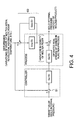
- FIG. 4 is a block diagram of the mold internal pressure feed forward control system according to the present invention.
- a feedback control system 60 is added to the feed forward control system described in conjunction with Fig. 3.
- the feedback control system 60 is used for performing feedback of variations in density of the molten resin measured by a measuring device for measuring the density of the molten resin.
- the feedback control system 60 is operated in the plasticizing process, and devised to eliminate the effects of uncertainties, which are found in the conventional system, by minimizing variations in density of the molten resin by the feedback control system 60 before beginning the injection process.
- any one of the number of revolutions of the screw, the backing pressure of the screw, and the heating cylinder temperature is controlled by the use of the value detected by the measuring device for measuring the density of the molten resin to minimize variations thereof.
- the control of the number of revolutions of the screw 20 may be realized by controlling the servomotor 24.
- the control of the number of revolution of the screw 20 may be realized by controlling the injection servomotor 11.
- the control of the temperature of the heating cylinder 21 is realized by controlling the heaters 40.
- the injection molding machine to which this embodiment is applied is predicated on the structure as described below.
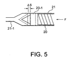
- the injection molding machine of this embodiment comprises a checking mechanism at the head portion of the screw, and the checking mechanism being closed before injection, wherein measurement of the density of the molten resin may be performed by pressing the screw.
- the density of the molten resin is detected in such a manner that, upon completion of measuring process, the checking mechanism 20-1 isolates the forward section of the head portion of the screw 20 and the measuring portion in the heating cylinder 21, then the injection servomotor 11 (See Fig.
- the feed forward control is performed as described in conjunction with Fig. 3 in the injecting process.
- the injection servomotor 11 controls the injection stroke of the screw 20.
- control of the servomotor 24, or control of the temperature of the heating cylinder 21 may be employed instead of control of the injection servomotor 11.
- the feed forward control system in which variations in weight of the molded product is zero in theory may be easily designed, thus realizing improved quality of the molded products with no variation in weight thereof.
- FIG. 6 is a block diagram showing the control system for implementing the controlling method according to the second embodiment.
- Gc (S) represents a transfer function in the controller
- Gp (S) represents a transfer function of the process.
- G2p (S) represents a disturbance, which is a transfer function for converting variations in measuring time period into variations in density of the molten resin.
- G3P (S) represents a transfer function for converting variations in driving torque of the screw into variations in density of the molten resin.
- the block diagram shows that the feed forward control reduces variations in density of the molten resin that is effected by disturbance, that is, by measuring time period or variations in the driving torque of the screw.
- the injection molding machine that is shown in the second embodiment is also predicted on the structure in which the density of the molten resin may be measured by the measuring device for the density of the molten resin as described in conjunction with the first embodiment.
- the second controlling method according to the second embodiment can simplify the design of the feed forward control system, which has been alleged to be difficult.
- the density of the molten resin can be stabilized, thereby presenting the controlling method wherein variations in weight of the molded products may be minimized.
- the present invention is also applicable to a hydraulic injection molding machine.
- an injection cylinder driven by hydraulic pressure is used instead of the rotational motion - linear motion converting mechanism by the use of ball screw and nut as in the injection apparatus shown in Fig. 1.
- the injection stroke is controlled by controlling hydraulic pressure applied on the injection cylinder.
Landscapes
- Engineering & Computer Science (AREA)
- Manufacturing & Machinery (AREA)
- Mechanical Engineering (AREA)
- Injection Moulding Of Plastics Or The Like (AREA)
Applications Claiming Priority (5)
| Application Number | Priority Date | Filing Date | Title |
|---|---|---|---|
| JP2000085958A JP3277490B2 (ja) | 2000-03-27 | 2000-03-27 | 射出成形機の制御方法 |
| JP2000085958 | 2000-03-27 | ||
| JP2000103341A JP3309280B2 (ja) | 2000-04-05 | 2000-04-05 | 射出成形機の制御方法 |
| JP2000103341 | 2000-04-05 | ||
| EP01102115A EP1138458B1 (de) | 2000-03-27 | 2001-01-31 | Verfahren zur Steuerung einer Spritzgiessmaschine durch Verminderung von Unterschieden der Kunststoffschmelzedichte |
Related Parent Applications (2)
| Application Number | Title | Priority Date | Filing Date |
|---|---|---|---|
| EP01102115.1 Division | 2001-01-31 | ||
| EP01102115A Division EP1138458B1 (de) | 2000-03-27 | 2001-01-31 | Verfahren zur Steuerung einer Spritzgiessmaschine durch Verminderung von Unterschieden der Kunststoffschmelzedichte |
Publications (1)
| Publication Number | Publication Date |
|---|---|
| EP1475212A1 true EP1475212A1 (de) | 2004-11-10 |
Family
ID=26588389
Family Applications (2)
| Application Number | Title | Priority Date | Filing Date |
|---|---|---|---|
| EP01102115A Expired - Lifetime EP1138458B1 (de) | 2000-03-27 | 2001-01-31 | Verfahren zur Steuerung einer Spritzgiessmaschine durch Verminderung von Unterschieden der Kunststoffschmelzedichte |
| EP04004377A Withdrawn EP1475212A1 (de) | 2000-03-27 | 2001-01-31 | Verfahren und Vorrichtung zum Steuern einer Spritzgiessmaschine geeignet zum Reduzieren der Gewichtsänderungen von Formkörpern |
Family Applications Before (1)
| Application Number | Title | Priority Date | Filing Date |
|---|---|---|---|
| EP01102115A Expired - Lifetime EP1138458B1 (de) | 2000-03-27 | 2001-01-31 | Verfahren zur Steuerung einer Spritzgiessmaschine durch Verminderung von Unterschieden der Kunststoffschmelzedichte |
Country Status (8)
| Country | Link |
|---|---|
| US (1) | US6555034B2 (de) |
| EP (2) | EP1138458B1 (de) |
| KR (2) | KR100405834B1 (de) |
| CN (2) | CN1256230C (de) |
| AT (1) | ATE292006T1 (de) |
| DE (1) | DE60109673T2 (de) |
| SG (1) | SG91321A1 (de) |
| TW (1) | TW587009B (de) |
Cited By (1)
| Publication number | Priority date | Publication date | Assignee | Title |
|---|---|---|---|---|
| CN102601950A (zh) * | 2012-01-16 | 2012-07-25 | 上海智觉光电科技有限公司 | 一种基于模糊算法的目标监视检测方法及系统 |
Families Citing this family (16)
| Publication number | Priority date | Publication date | Assignee | Title |
|---|---|---|---|---|
| US7103445B2 (en) | 2002-11-27 | 2006-09-05 | Kimberly-Clark Worldwide, Inc. | System and method for controlling the dispense rate of particulate material |
| KR101201789B1 (ko) * | 2004-12-10 | 2012-11-16 | 한국항공우주산업 주식회사 | 가열성형기의 제어방법 |
| DE102007020365A1 (de) * | 2007-04-30 | 2008-11-13 | Siemens Ag | Lagerbaugruppe mit integriertem Messsystem |
| US20090057938A1 (en) * | 2007-08-28 | 2009-03-05 | Husky Injection Molding Systems Ltd. | Closed Loop Control for an Injection Unit |
| CN102079125B (zh) * | 2010-12-22 | 2013-04-17 | 浙江大学 | 一种注塑成型塑料镜片焦距无模型控制方法 |
| CN102101352B (zh) * | 2010-12-22 | 2013-08-07 | 浙江大学 | 一种注塑成型制品重量无模型控制方法 |
| KR101273164B1 (ko) * | 2011-01-27 | 2013-06-14 | 엘에스엠트론 주식회사 | 사출성형기의 스크류 제어 방법 |
| JP5731933B2 (ja) * | 2011-08-30 | 2015-06-10 | 川崎重工業株式会社 | 適応制御装置および適応制御方法ならびに射出成形機の制御装置および制御方法 |
| JP5727536B2 (ja) * | 2013-03-11 | 2015-06-03 | ファナック株式会社 | 力伝達部の温度管理機能を有する射出成形機の制御装置 |
| AT516452B1 (de) * | 2014-08-14 | 2016-08-15 | Engel Austria Gmbh | Plastifiziereinheit für eine Spritzgießmaschine |
| TWI607853B (zh) * | 2015-08-10 | 2017-12-11 | 和碩聯合科技股份有限公司 | 提供成型機台之成型參數的方法 |
| CN106427004A (zh) * | 2016-12-19 | 2017-02-22 | 东莞市广信知识产权服务有限公司 | 一种制鞋用鞋底成型控制系统及其工艺 |
| JP7498087B2 (ja) * | 2020-10-20 | 2024-06-11 | 株式会社日本製鋼所 | 連続混練装置及びその制御方法 |
| JP7528005B2 (ja) * | 2021-02-26 | 2024-08-05 | 住友重機械工業株式会社 | 射出成形機 |
| CN113799350B (zh) * | 2021-08-23 | 2023-07-21 | 西诺控股集团有限公司 | 一种智能检测塑化能力的控制方法和装置 |
| CN119189239A (zh) * | 2024-11-27 | 2024-12-27 | 博创智能装备股份有限公司 | 一种注塑机多维度的电熔胶控制方法 |
Citations (6)
| Publication number | Priority date | Publication date | Assignee | Title |
|---|---|---|---|---|
| US4326255A (en) * | 1978-04-13 | 1982-04-20 | Toshiba Kikai Kabushiki Kaisha | Apparatus for controlling plasticizing process of in-line screw-type injection molding machine |
| US5075050A (en) * | 1987-08-07 | 1991-12-24 | Bo Nilsson | Method for controlling some parameters in connection with manufacturing of plastic articles |
| JPH04110119A (ja) * | 1990-08-29 | 1992-04-10 | Sekisui Chem Co Ltd | 射出成形方法 |
| JPH09254219A (ja) * | 1996-03-21 | 1997-09-30 | Matsushita Electric Works Ltd | 射出成形方法 |
| JPH1134133A (ja) * | 1997-07-18 | 1999-02-09 | Sumitomo Heavy Ind Ltd | 溶融樹脂の密度の検出方法 |
| JP2000052391A (ja) * | 1998-08-10 | 2000-02-22 | Japan Steel Works Ltd:The | 射出成形機の温度制御方法 |
Family Cites Families (1)
| Publication number | Priority date | Publication date | Assignee | Title |
|---|---|---|---|---|
| JPH04336222A (ja) | 1991-05-14 | 1992-11-24 | Sumitomo Jukikai Plast Mach Kk | 射出成形機のノズル内樹脂圧による制御方法 |
-
2000
- 2000-12-30 SG SG200007706A patent/SG91321A1/en unknown
-
2001
- 2001-01-02 US US09/750,722 patent/US6555034B2/en not_active Expired - Fee Related
- 2001-01-18 TW TW090101108A patent/TW587009B/zh not_active IP Right Cessation
- 2001-01-31 EP EP01102115A patent/EP1138458B1/de not_active Expired - Lifetime
- 2001-01-31 DE DE60109673T patent/DE60109673T2/de not_active Expired - Lifetime
- 2001-01-31 EP EP04004377A patent/EP1475212A1/de not_active Withdrawn
- 2001-01-31 AT AT01102115T patent/ATE292006T1/de not_active IP Right Cessation
- 2001-02-13 KR KR10-2001-0006900A patent/KR100405834B1/ko not_active Expired - Fee Related
- 2001-03-01 CN CNB031562760A patent/CN1256230C/zh not_active Expired - Fee Related
- 2001-03-01 CN CNB011092513A patent/CN1141210C/zh not_active Expired - Fee Related
-
2003
- 2003-07-16 KR KR10-2003-0048518A patent/KR100405835B1/ko not_active Expired - Fee Related
Patent Citations (6)
| Publication number | Priority date | Publication date | Assignee | Title |
|---|---|---|---|---|
| US4326255A (en) * | 1978-04-13 | 1982-04-20 | Toshiba Kikai Kabushiki Kaisha | Apparatus for controlling plasticizing process of in-line screw-type injection molding machine |
| US5075050A (en) * | 1987-08-07 | 1991-12-24 | Bo Nilsson | Method for controlling some parameters in connection with manufacturing of plastic articles |
| JPH04110119A (ja) * | 1990-08-29 | 1992-04-10 | Sekisui Chem Co Ltd | 射出成形方法 |
| JPH09254219A (ja) * | 1996-03-21 | 1997-09-30 | Matsushita Electric Works Ltd | 射出成形方法 |
| JPH1134133A (ja) * | 1997-07-18 | 1999-02-09 | Sumitomo Heavy Ind Ltd | 溶融樹脂の密度の検出方法 |
| JP2000052391A (ja) * | 1998-08-10 | 2000-02-22 | Japan Steel Works Ltd:The | 射出成形機の温度制御方法 |
Non-Patent Citations (7)
| Title |
|---|
| DATABASE WPI Derwent World Patents Index; AN 1997-531463, XP002179164 * |
| DATABASE WPI Week 199917, Derwent World Patents Index; AN 1999-193359, XP002179165 * |
| DATABASE WPI Week 200020, Derwent World Patents Index; AN 2000-232183, XP002296634 * |
| PATENT ABSTRACTS OF JAPAN vol. 016, no. 353 (M - 1288) 30 July 1992 (1992-07-30) * |
| PATENT ABSTRACTS OF JAPAN vol. 1998, no. 01 30 January 1998 (1998-01-30) * |
| PATENT ABSTRACTS OF JAPAN vol. 1999, no. 05 31 May 1999 (1999-05-31) * |
| PATENT ABSTRACTS OF JAPAN vol. 2000, no. 05 14 September 2000 (2000-09-14) * |
Cited By (2)
| Publication number | Priority date | Publication date | Assignee | Title |
|---|---|---|---|---|
| CN102601950A (zh) * | 2012-01-16 | 2012-07-25 | 上海智觉光电科技有限公司 | 一种基于模糊算法的目标监视检测方法及系统 |
| CN102601950B (zh) * | 2012-01-16 | 2014-04-23 | 上海智觉光电科技有限公司 | 一种基于模糊算法的目标监视检测方法及系统 |
Also Published As
| Publication number | Publication date |
|---|---|
| TW587009B (en) | 2004-05-11 |
| CN1495009A (zh) | 2004-05-12 |
| DE60109673T2 (de) | 2006-03-09 |
| CN1141210C (zh) | 2004-03-10 |
| EP1138458A2 (de) | 2001-10-04 |
| US6555034B2 (en) | 2003-04-29 |
| SG91321A1 (en) | 2002-09-17 |
| DE60109673D1 (de) | 2005-05-04 |
| EP1138458A3 (de) | 2001-12-05 |
| KR100405834B1 (ko) | 2003-11-14 |
| CN1315244A (zh) | 2001-10-03 |
| ATE292006T1 (de) | 2005-04-15 |
| KR20030063332A (ko) | 2003-07-28 |
| KR20010090715A (ko) | 2001-10-19 |
| EP1138458B1 (de) | 2005-03-30 |
| CN1256230C (zh) | 2006-05-17 |
| KR100405835B1 (ko) | 2003-11-14 |
| US20010023996A1 (en) | 2001-09-27 |
Similar Documents
| Publication | Publication Date | Title |
|---|---|---|
| US6555034B2 (en) | Method for controlling an injection molding machine capable of reducing variations in weight of molded products | |
| JP2537089B2 (ja) | 射出成形機の自動給脂方法 | |
| US10513071B2 (en) | Pressure controller for injection molding machine | |
| JP3255609B2 (ja) | 電動射出成形機の射出速度切換制御方法 | |
| JPH0440178B2 (de) | ||
| KR20000006223A (ko) | 전동사출성형기의가소화/계량공정에서의제압방법 | |
| US4879077A (en) | Control method of injection molding machine | |
| EP1136226B1 (de) | Verfahren und Vorrichtung zum Steuern einer Spritzgiessmaschine geeignet zum Reduzieren der Gewichtsänderungen von Formkörpern | |
| US6565781B2 (en) | Method for controlling screw position in an injection molding machine | |
| EP1207032B1 (de) | Verfahren zum Steuern einer Spritzgiessmaschine geeignet zum Reduzieren der Gewichtsänderungen von Formkörpern | |
| JP3309280B2 (ja) | 射出成形機の制御方法 | |
| US7914716B2 (en) | Measurement control method of an injection molding machine | |
| JP3277490B2 (ja) | 射出成形機の制御方法 | |
| JPH0544898B2 (de) | ||
| KR200348431Y1 (ko) | 사출성형기의 배압 제어장치 | |
| JPH06320586A (ja) | 射出成形機の可塑化制御方法及び装置 | |
| JP4248504B2 (ja) | 射出成形機の射出制御方法およびその射出装置 | |
| JP2006116789A (ja) | 成形機及びその樹脂供給制御方法 | |
| JPH059256B2 (de) | ||
| JPH0939051A (ja) | 射出プレス成形方法および装置 | |
| JPH07214622A (ja) | 射出成形機における樹脂温度の測定装置 | |
| JPH0512136B2 (de) |
Legal Events
| Date | Code | Title | Description |
|---|---|---|---|
| PUAI | Public reference made under article 153(3) epc to a published international application that has entered the european phase |
Free format text: ORIGINAL CODE: 0009012 |
|
| AC | Divisional application: reference to earlier application |
Ref document number: 1138458 Country of ref document: EP Kind code of ref document: P |
|
| AK | Designated contracting states |
Kind code of ref document: A1 Designated state(s): AT CH DE FR GB IT LI |
|
| 17P | Request for examination filed |
Effective date: 20050408 |
|
| 17Q | First examination report despatched |
Effective date: 20050527 |
|
| AKX | Designation fees paid |
Designated state(s): DE |
|
| STAA | Information on the status of an ep patent application or granted ep patent |
Free format text: STATUS: THE APPLICATION HAS BEEN WITHDRAWN |
|
| 18W | Application withdrawn |
Effective date: 20091112 |