EP1475220A2 - Verfahren zur Herstellung eines dreidimensionalen Modells und dreidimensionales Modell - Google Patents
Verfahren zur Herstellung eines dreidimensionalen Modells und dreidimensionales Modell Download PDFInfo
- Publication number
- EP1475220A2 EP1475220A2 EP04009668A EP04009668A EP1475220A2 EP 1475220 A2 EP1475220 A2 EP 1475220A2 EP 04009668 A EP04009668 A EP 04009668A EP 04009668 A EP04009668 A EP 04009668A EP 1475220 A2 EP1475220 A2 EP 1475220A2
- Authority
- EP
- European Patent Office
- Prior art keywords
- binder
- dimensional model
- powder material
- layer
- cross
- Prior art date
- Legal status (The legal status is an assumption and is not a legal conclusion. Google has not performed a legal analysis and makes no representation as to the accuracy of the status listed.)
- Withdrawn
Links
Images
Classifications
-
- B—PERFORMING OPERATIONS; TRANSPORTING
- B29—WORKING OF PLASTICS; WORKING OF SUBSTANCES IN A PLASTIC STATE IN GENERAL
- B29C—SHAPING OR JOINING OF PLASTICS; SHAPING OF MATERIAL IN A PLASTIC STATE, NOT OTHERWISE PROVIDED FOR; AFTER-TREATMENT OF THE SHAPED PRODUCTS, e.g. REPAIRING
- B29C64/00—Additive manufacturing, i.e. manufacturing of three-dimensional [3D] objects by additive deposition, additive agglomeration or additive layering, e.g. by 3D printing, stereolithography or selective laser sintering
- B29C64/10—Processes of additive manufacturing
- B29C64/165—Processes of additive manufacturing using a combination of solid and fluid materials, e.g. a powder selectively bound by a liquid binder, catalyst, inhibitor or energy absorber
-
- B—PERFORMING OPERATIONS; TRANSPORTING
- B33—ADDITIVE MANUFACTURING TECHNOLOGY
- B33Y—ADDITIVE MANUFACTURING, i.e. MANUFACTURING OF THREE-DIMENSIONAL [3D] OBJECTS BY ADDITIVE DEPOSITION, ADDITIVE AGGLOMERATION OR ADDITIVE LAYERING, e.g. BY 3D PRINTING, STEREOLITHOGRAPHY OR SELECTIVE LASER SINTERING
- B33Y10/00—Processes of additive manufacturing
-
- B—PERFORMING OPERATIONS; TRANSPORTING
- B33—ADDITIVE MANUFACTURING TECHNOLOGY
- B33Y—ADDITIVE MANUFACTURING, i.e. MANUFACTURING OF THREE-DIMENSIONAL [3D] OBJECTS BY ADDITIVE DEPOSITION, ADDITIVE AGGLOMERATION OR ADDITIVE LAYERING, e.g. BY 3D PRINTING, STEREOLITHOGRAPHY OR SELECTIVE LASER SINTERING
- B33Y70/00—Materials specially adapted for additive manufacturing
- B33Y70/10—Composites of different types of material, e.g. mixtures of ceramics and polymers or mixtures of metals and biomaterials
-
- B—PERFORMING OPERATIONS; TRANSPORTING
- B29—WORKING OF PLASTICS; WORKING OF SUBSTANCES IN A PLASTIC STATE IN GENERAL
- B29K—INDEXING SCHEME ASSOCIATED WITH SUBCLASSES B29B, B29C OR B29D, RELATING TO MOULDING MATERIALS OR TO MATERIALS FOR MOULDS, REINFORCEMENTS, FILLERS OR PREFORMED PARTS, e.g. INSERTS
- B29K2995/00—Properties of moulding materials, reinforcements, fillers, preformed parts or moulds
- B29K2995/0018—Properties of moulding materials, reinforcements, fillers, preformed parts or moulds having particular optical properties, e.g. fluorescent or phosphorescent
- B29K2995/002—Coloured
Definitions
- the present invention relates to a process for producing a three-dimensional model and production equipment used therefor and, in particular, to a process for producing a three-dimensional model by sequentially layering a plurality of sliced cross-sectional shapes of a three-dimensional model of an object, and production equipment used therefor.
- a model which is a three-dimensional model of a solid modeled object, by imagewise bonding with a binder a thin powder layer for each of a plurality of sliced cross-sectional shapes of the modeled object, and sequentially layering these bonded thin cross-sectional shaped layers.
- a thin layer of a powder is spread on a flat surface by means of a blade mechanism so as to have a uniform thickness, and an inkjet nozzle head is made to scan and discharge a binder onto the surface of the thin powder layer according to a cross-sectional shape based on cross-sectional data of the modeled object.
- the powder material in the region where the binder has been discharged is subjected to an operation necessary to put it into a bonded state and also to bond it to the cross-sectional shape of a lower layer that has already been formed.
- powder in a region to which no binder has been applied can be removed easily when taking out the model from the equipment and the target model can be separated because the powder particles are separate and not bonded to each other.
- a desired three-dimensional model can be produced.
- JP-A denotes a Japanese unexamined patent application publication
- the three-dimensional model immediately after forming is shaped only by virtue of the bonding force of the binder, the three-dimensional model has a low strength and, depending on the way it is handled, might be broken. Conventionally, therefore, after forming the three-dimensional model it is impregnated with a resin, a wax, etc. between the powder particles in order to increase the strength. However, such a step requires time and effort.
- the object of the present invention can be attained by the following means (1) to (3).
- a three-dimensional model having highly precise dimensions, and excellent coloration, mechanical strength, surface gloss, and texture can be produced, and a high quality three-dimensional model, which has been impossible to produce, can be produced simply at low cost.
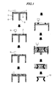
- FIG. 1 is a schematic view showing each step of one embodiment of the process for producing a three-dimensional model of the present invention.
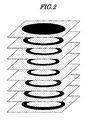
- FIG. 2 is a perspective view showing schematically the cross-sectional shape of several layers formed in the production of the three-dimensional model shown in FIG. 1.
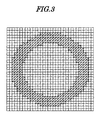
- FIG. 3 is a plan view showing one example of cross-sectional data finely divided into a grid.
- the present invention relates to a process for producing a three-dimensional model, the process comprising sequentially repeating a step (layer formation step) of forming a layer of a powder material above a support, the layer having a predetermined thickness, and a step (cross-sectional shape formation step) of imagewise bonding the powder material layer by a binder according to cross-sectional data of a modeled object so as to give a cross-sectional shape, the surface gloss of the three-dimensional model obtained when measured at 20° being 20% or more. Furthermore, the present invention relates to a three-dimensional model comprising a powder material and a binder and formed by imagewise curing the binder, the three-dimensional model having a surface gloss when measured at 20° of 20% or more.
- the surface gloss of the three-dimensional model obtained by the production process of the present invention when measured at 20° is 20% or more, preferably 30% or more, and more preferably 40% or more.
- the surface gloss referred to in the present invention is the surface gloss measured at an incident angle of 20°, and can be measured using, for example, a UGV-6P Digital Variable Angle Gloss Meter (Suga Test Instruments Co., Ltd.).
- a binder to the outermost layer of the model at a level of 1.05 to 5.0 times, and preferably 1.1 to 2.5 times, the amount of binder applied to the interior of the model.
- this scaling factor is also called the 'discharge scaling factor (application scaling factor)'.
- 'the outermost layer of the model' referred to in the present invention means a surface of the model that can be seen externally by a normal observation method.
- the model is a single body, it is the external outline of the model and corresponds to the whole cross-sectional shape of the lowermost layer forming the base, outline portions of cross-sectional shapes in the middle, and the cross-sectional shape of the uppermost layer forming the top.
- the amount of binder discharged onto the outer surface of the model can be increased, and the amount discharged onto the inner surface, which is usually unseen, may be the same as that for the interior of the model.
- the surfaces of two concentric circular rings and a plurality of balls inserted therebetween are areas that can be seen externally, and the entire outer surfaces of the two rings and the plurality of balls corresponds to the outermost layer.
- the relationship between the outermost layer and grid points of a bitmap in which a cross-sectional shape is further microscopically and finely divided into a grid will be described later.
- the average particle size of the powder material is preferably 50 ⁇ m or less, and more preferably 1 to 30 ⁇ m. When the average particle size is in the above-mentioned range, the surface gloss of the three-dimensional model obtained increases, which is preferable.
- the average particle size referred to here means a volume-average particle size, and can be measured by, for example, a COULTER MULTISIZER manufactured by Beckman Coulter, Inc.
- the particle size distribution can be wide, but is preferably narrow. It is preferable for the particle size distribution to be nearly monodisperse, and the coefficient of variation of the particle size distribution is preferably 20% or less, and more preferably 15% or less.
- the powder material can be an organic material, an inorganic material, or an inorganic/organic composite material. Details thereof will be explained later.
- a support having any surface profile can be used, but a support having a smooth surface is preferable, and a support having a flat surface can be used preferably.
- the predetermined thickness for the powder material layer is preferably a layer having a thickness of 10 to 500 ⁇ m per slice pitch, and more preferably 50 to 150 ⁇ m.
- the overall thickness of the stack of powder material layers increases by the above-mentioned slice pitch.
- the colored cross-sectional shape referred to here means a shape that corresponds to one of a plurality of sliced cross sections of a modeled object, and that is accompanied by coloring.
- the cross-sectional shape of an opaque model can be a hollow shape, and in this case it is sufficient to reproduce the shape in the vicinity of the outline thereof. With regard to coloration, color may be reproduced on the surface alone of the model, and color reproduction of the outline of the shape is important.
- FIG. 1 is a schematic view showing the main steps of one embodiment of the process for producing a three-dimensional model of the present invention.
- a thin layer 1 of a powder material is formed above a support (modeling stage) 4 provided in a three-dimensional modeling section 3.
- the support 4 is supported by a vertically moving section 5 and its perimeter is surrounded by a frame 6.
- the thin layer 1 is formed by a blade 7, which extends lengthwise in a direction Y (a direction perpendicular to the plane of the paper), moving in a direction X (the left-to-right direction in the plane of the paper) on surplus powder material, which is supplied from a powder supply section to the support 4.
- a binder is supplied to the top of the thus-formed thin layer 1 of the powder material, via an inkjet head 8 of a binder application section, according to cross-sectional shape data so as to form a region 2 to which the binder has been applied.
- This region 2 to which the binder has been applied is cured by exposure to ultraviolet rays from an ultraviolet irradiation section 9, and a cross-sectional shape is formed by bonding the powder material throughout the thickness of the thin layer in the region 2 to which the binder has been applied, and also by bonding it to the cross-sectional shape that is directly below.
- the vertically moving section 5 is moved downward by 1 slice pitch, and a new powder material layer is formed.
- Binder is supplied to the top of the newly formed thin layer via the inkjet head of the binder application section according to the next adjacent cross-sectional shape data so as to form a new region to which binder has been applied. This region is cured by exposure to ultraviolet rays so as to bond the powder material.
- a three-dimensional model 10 can be obtained by separating the powder material in the region where no binder has been applied.
- FIG. 2 is a perspective view showing schematically the cross-sectional shape formed in each of the adjacent layers in the production of the above-mentioned three-dimensional model.
- a preferred embodiment of the process for producing a three-dimensional model of the present invention is explained below.
- the five steps below include a step of preparing three-dimensional shape color data and a step of preparing colored cross-sectional shape data for each cross section, prior to the (powder) layer formation step and the colored cross-sectional shape formation step.
- model data representing a three-dimensional modeled object having on its surface a color pattern, etc. are created in a computer.
- model data used as a basis for modeling color three-dimensional model data formed by general 3D-CAD modeling software can be used. It is also possible to utilize data and texture of a three-dimensional colored shape measured using a three-dimensional shape input device.
- cross-sectional data for each horizontally sliced cross section of the modeled object are formed in a computer from the above-mentioned model data.
- a cross-sectional body sliced at a pitch (layer thickness t ) corresponding to the thickness of one layer of the layered powder is cut out of the model data, and shape data and coloration data showing a region where the cross section is present are formed as the cross-sectional data.
- data (STL format, etc.) obtained using three-dimensional CAD can be converted into cross-sectional data sliced at a thickness of 10 to 500 ⁇ m.
- 'shape data' and 'coloration data' are together also called 'colored (cross-sectional) shape data'.
- a powder material which is the material for producing the three-dimensional model on the modeling stage.
- the powder material is spread in a uniformly thick layer shape using a powder material counter-rotating mechanism (hereinafter, called a 'counter roller'), and supply of the powder material is stopped when a predetermined amount of powder has been supplied.
- 'Sequentially repeating the layer formation step and the cross-sectional shape formation step' referred to in the present invention means not only (1) carrying out a step of forming a cross-sectional shape on the whole surface of a new layer after completing a new layer formation step, but also (2) forming a cross-sectional shape in a region of a newly formed layer before formation of the newly formed layer is completed, while still carrying out the new layer formation step.
- An example of the latter case has been disclosed in JP-A-2002-307562.
- a fourth step is a step of forming a colored cross-sectional shape under the control of the drive control section according to the colored shape data for the cross section.
- This step preferably employs a non-contact method. As a representative example, an inkjet method is explained.
- the shape data and the coloration data created in the second step are converted into finely divided grids of bitmap information for each color of C, M, and Y, and an inkjet head is moved within the XY plane. During the movement, an ultraviolet (UV)-curing binder is discharged appropriately from each inkjet discharge nozzle based on the coloration data.
- UV ultraviolet
- the binder it is preferable to use two or more types of binders selected from the group consisting of at least one type of colored binder, a white binder, and a colorless transparent binder.
- the colored binder does not include a white colored binder.
- a binder to at least one grid point positioned in the outermost layer of the model at a level of 1.05 to 5.0 times, and preferably 1.1 to 2.5 times, the amount of binder applied to a grid point positioned in the interior of the model.
- the amount of binder is in the above-mentioned range, the surface gloss and the strength of the model improve, which is preferable.
- Said at least one grid point positioned in the outermost layer of the model includes a grid point of the whole cross-sectional shape of the lowermost layer of the model, a grid point of the whole cross-sectional shape of the uppermost layer, and a grid point (outline grid point) forming the external outline of a cross-sectional shape of a middle layer positioned between the lowermost layer and the uppermost layer, and can include one or a plurality of grid points adjacent to the above grid points (adjacent grid point).
- the discharge scaling factor can be adjusted so as to have an appropriate gradation. When it is adjusted, it is not necessary to make the outline grid point have the maximum scaling factor, and it is possible to make the discharge scaling factor of the adjacent grid point immediately next to the outline grid point the maximum.
- the discharge scaling factor can be selected appropriately. When the discharge scaling factor is too large, there is a possibility that spreading of the outline might occur, and when the discharge scaling factor is small, a desired surface effect cannot be obtained.
- FIG. 3 is a plan view showing one example of finely divided grid cross-sectional data generated in the second step.
- the hatched grids correspond to regions where a binder is discharged.
- the discharge scaling factor for grid points positioned in the outermost layer of the model is increased so as to be in the above-mentioned range.
- For the cross-sectional shapes in the middle a larger amount of binder is discharged to the outline grid points corresponding to the outer surface than is discharged to the inside grid points.
- the discharge scaling factor can be increased for several adjacent grid points adjacent to the outline grid point.
- the 'several adjacent grid points' are preferably 1 to 10 grid points, and more preferably 1 to 5 grid points.
- Adjustment of the discharge scaling factor can be carried out by changing the amount of discharge per unit time, and/or increasing the number of times of discharge at the same grid point.
- Control is simple when the discharge scaling factor of the outline grid points alone is increased.
- the discharge scaling factor for the outline grid points alone is made 2 times that for the inside grid points, etc. It is also possible to set the discharge scaling factor of every other adjacent grid point to be 2 times.
- Control of the number of times of discharge is more simple than control of the amount discharged per unit time.
- the amounts discharged for the outline grid points and one layer of adjacent grid points are increased by adjusting the number of times of discharge to once, twice, or three times.
- the discharge scaling factor By adjusting the amount of binder discharged per unit time to 0.66 to 1.5 times, the discharge scaling factor can be adjusted more finely. Combining this with adjustment of the number of times of discharge onto 1 grid point, adjustment of the discharge scaling factor can be carried out even more finely.
- the binder spreads beyond a predetermined region, and there is a tendency for the surface smoothness of the three-dimensional model obtained to be impaired.
- the spreading of the binder can be prevented by a measure in which a spread-preventing liquid that is not compatible with the binder is disposed along the outline outside the outline grid points of the cross-sectional shape of the model.
- an ultraviolet-curing compound which will be described later, is used as the binder, as the spread-preventing liquid, water, methanol, ethanol, butanol, hexanol, ethylene glycol, butanediol, glycerol, diethyl ether, propyl ether, or a hydrocarbon having up to 14 carbons such as hexane, heptane, octane, or decane, which have no compatibility with the ultraviolet-curing compound, can be used singly or as a mixture.
- a black dye-colored binder black binder
- a yellow-colored binder is called a 'yellow binder'
- a magenta-colored binder is called a 'magenta binder'
- a cyan-colored binder is called a 'cyan binder'.
- An M dye and a C dye may each comprise two, that is, dark- and pale-colored, types of binders.
- the colorless binder can be used in order to adjust the CMY color densities.
- a desired effect can be attained by the combined use of a binder (white binder) containing a white (W) pigment such as titanium white.
- the total amount of colored binder, colorless binder, and white binder discharged is preferably constant per unit area, for example, per grid point or per four adjacent grid points. As hereinbefore described, it is a characteristic of the present invention that the total amount of binders in the outline grid points is set so that it is increased by a predetermined discharge scaling factor.
- the object of the present invention can be achieved by increasing the discharge scaling factor of the colorless binder at the outline grid points.
- the surface of the discharged binder is exposed to ultraviolet rays using an ultraviolet irradiation device, thus forming a powder material bonded body.
- the atmosphere for the UV irradiation is an atmosphere of an inert gas such as nitrogen or argon, the effect of oxygen in delaying radical polymerization of a polymerizable compound can be suppressed.
- the inkjet system employed here means mainly an on-demand inkjet system, which includes a piezo on-demand inkjet system, a thermal on-demand inkjet system, and an electrostatic on-demand inkjet system, and the piezo on-demand inkjet system and the electrostatic on-demand inkjet system are preferable in terms of stability of the UV-curing binder.
- the powder In a powder material region to which no binder is applied, the powder is maintained in a separated state.
- a fifth step the powder material in a region to which no binder has been applied is separated, and a bonded powder body (three-dimensional model) imagewise bonded by the binder is taken out.
- the powder material that has not been bonded is recovered and can be reused.
- a transparent or substantially transparent three-dimensional model By bonding into a cross-sectional shape a layer of a powder material having a refractive index n 1 by means of a binder that gives a refractive index n 2 (here, -0.1 ⁇ (n 1 -n 2 ) ⁇ 0.1), a transparent or substantially transparent three-dimensional model can be produced.
- n 1 refractive index
- n 2 refractive index n 2
- the three-dimensional model thus obtained can be subjected to a posttreatment step such as cleaning, thermal treatment, resin or wax impregnation, or polishing.
- Cleaning is carried out by blowing the above-mentioned three-dimensional model and brushing so as to remove any powder remaining in gaps, thus enabling surplus powder to be removed.
- the thermal treatment increases the strength and the durability of the above-mentioned three-dimensional model.
- Wax impregnation reduces the porosity, imparts water resistance to the above-mentioned three-dimensional model, and makes finishing by polishing easy. Finishing by polishing improves the surface smoothness.
- any of an inorganic powder, an organic powder, and an inorganic/organic composite powder can be used.
- the inorganic powder include metals, oxides, composite oxides, hydroxides, carbonates, sulfates, silicates, phosphates, nitrides, carbides, sulfides, and composites of at least two types thereof.
- Specific examples thereof include magnesium hydroxide, silica gel, alumina, aluminum hydroxide, glass, titanium oxide, zinc oxide, zirconium oxide, tin oxide, potassium titanate, aluminum borate, magnesium oxide, magnesium borate, calcium hydroxide, basic magnesium sulfate, calcium carbonate, magnesium carbonate, calcium sulfate, magnesium sulfate, calcium silicate, magnesium silicate, calcium phosphate, silicon nitride, titanium nitride, aluminum nitride, silicon carbide, titanium carbide, zinc sulfide, and composites of at least two types thereof.
- Preferred examples include magnesium hydroxide, silica gel, alumina, aluminum hydroxide, glass, calcium carbonate, magnesium carbonate, calcium sulfate, and magnesium sulfate.
- organic powder examples include synthetic organic powders and natural polymer powders. Specific examples include acrylic resins, polyethylene, polypropylene, polyethylene oxide, polypropylene oxide, polyethyleneimine, polystyrene, polyurethane, polyurea, polyester, polyamide, polyimide, carboxymethyl cellulose, gelatin, starch, chitin, and chitosan, preferred examples include acrylic resins, polyurethane, gelatin, and polystyrene, and more preferred examples include polymer resin particles of a UV-curing binder formed from an acrylic resin.
- the organic powder material powder particles obtained by grinding a bulk-polymerized binder monomer can be used.
- the binder monomer is subjected to suspension polymerization or pearl polymerization, and a powder material having a desired particle size can be obtained.
- the refractive index of the powder material and the refractive index of the binder can be made similar.
- Examples of the inorganic/organic composite powder include a composite of the above-mentioned organic powder and inorganic powder.
- the shape of the powder material can be any of amorphous, spherical, tabular, acicular, porous, etc. forms.
- the refractive index n 1 of the powder material is preferably in the range of 1.4 to 1.7.
- the refractive index of a binder for bonding the powder material particles to each other is defined as n 2 .
- the refractive index of the bonding agent formed by polymerization of this monomer is defined as n 2 .
- the absolute value of the difference between the refractive indexes is 0.1 or less, the transparency is high, and when it is 0.06 or less, a nearly transparent model can be obtained.
- a UV-curing binder that includes an ultraviolet-curing compound can be used preferably.
- the UV-curing binder comprises a photopolymerization initiator and at least one type of polymerizable compound as essential components; substantially all of the constituent materials are cured by UV light, and have the function of bonding the powder material.
- the photopolymerization initiator is preferably 0.05 to 10 wt %, and more preferably 0.1 to 5 wt %
- the polymerizable compound is preferably 90 to 99.95 wt %, and more preferably 95 wt % to 99.9 wt %.
- the viscosity (25°C) of the binder solution is preferably 1 to 100 mPa ⁇ s, and more preferably 10 to 50 mPa ⁇ s. It is preferable to mix a polyfunctional monomer having high viscosity and a monofunctional monomer having low viscosity appropriately so as to attain the above viscosity range.
- 'binder' means the total amount of the binder and the pigment.
- the polymerizable compound that can be used in the UV-curing binder those for which addition-polymerization or ring-opening polymerization is started by a radical species, a cationic species, etc. formed from a photopolymerization initiator by irradiation with UV light and a polymer is formed are preferably used.
- a radical species, a cationic species, etc. formed from a photopolymerization initiator by irradiation with UV light and a polymer is formed are preferably used.
- there are radical, cationic, anionic, metathesis, and coordination polymerization there are radical, cationic, anionic, radical, metathesis, and coordination polymerization.
- an addition-polymerizable compound a compound having at least one ethylenically unsaturated double bond can be cited.
- a compound having at least one, and preferably two, terminal ethylenically unsaturated bonds can be used preferably.
- Such terminally ethylenically unsaturated compounds are widely known in the present industrial field. In the present invention, they can be used without particular restriction as long as the binder composition can be discharged stably from an inkjet nozzle.
- the ethylenically unsaturated polymerizable compound is, in terms of its chemical configuration, a monofunctional polymerizable compound, a polyfunctional polymerizable compound (i.e., difunctional, trifunctional, or 4- to 6-functional polymerizable compound, etc.), or a mixture thereof.
- the monofunctional polymerizable compound include unsaturated carboxylic acids (e.g., acrylic acid, methacrylic acid, itaconic acid, crotonic acid, isocrotonic acid, and maleic acid), esters thereof, and amides thereof.
- the polyfunctional polymerizable compound include esters of an unsaturated carboxylic acid and an aliphatic polyhydric alcohol compound and amides of an unsaturated carboxylic acid and an aliphatic polyhydric amine compound.
- a representative example of the radically polymerizable compound that is an ester of an unsaturated carboxylic acid and a aliphatic polyhydric alcohol compound is a (meth)acrylate ester, and specific examples thereof include ethylene glycol di(meth)acrylate, triethylene glycol di(meth)acrylate, 1,3-butanediol di(meth)acrylate, tetramethylene glycol di(meth)acrylate, propylene glycol di(meth)acrylate, neopentyl glycol di(meth)acrylate, trimethylolpropane tri(meth)acrylate, trimethylolpropane tri((meth)acryloyloxypropyl) ether, trimethylolethane tri(meth)acrylate, hexanediol di(meth)acrylate, 1,4-cyclohexanediol di(meth)acrylate, tetraethylene glycol di(meth)acrylate, pentaery
- an itaconate ester In addition to the (meth)acrylate ester, an itaconate ester, a crotonate ester, an isocrotonate ester, a maleate ester, etc. can also be used as the polymerizable compound.
- the itaconate ester examples include ethylene glycol diitaconate, propylene glycol diitaconate, 1,3-butanediol diitaconate, 1,4-butanediol diitaconate, tetramethylene glycol diitaconate, pentaerythritol diitaconate, and sorbitol tetraitaconate.
- crotonate ester examples include ethylene glycol dicrotonate, tetramethylene glycol dicrotonate, pentaerythritol dicrotonate, and sorbitol tetracrotonate.
- isocrotonate ester examples include ethylene glycol diisocrotonate, pentaerythritol diisocrotonate, and sorbitol tetraisocrotonate.
- maleate ester examples include ethylene glycol dimaleate, triethylene glycol dimaleate, pentaerythritol dimaleate, and sorbitol tetramaleate.
- esters examples include aliphatic alcohol esters disclosed in, for example, JP-B-46-27926, JP-B-51-47334 (JP-B denotes a Japanese examined patent application publication), and JP-A-57-196231, those having an aromatic skeleton disclosed in JP-A-59-5240, JP-A-59-5241, and JP-A-2-226149, and those containing an amino group disclosed in JP-A-1-165613.
- amide monomer of an unsaturated carboxylic acid and an aliphatic polyhydric amine compound examples include methylenebisacrylamide, methylenebismethacrylamide, 1,6-hexamethylenebisacrylamide, 1,6-hexamethylenebismethacrylamide, diethylenetriaminetrisacrylamide, xylylenebisacrylamide, and xylylenebismethacrylamide.
- amide monomers include those having a cyclohexylene structure disclosed in JP-B-54-21726.
- an addition-polymerizable urethane compound produced by an addition reaction of an isocyanate and a hydroxyl group is also desirable, and specific examples thereof include a vinylurethane compound having at least two polymerizable vinyl groups per molecule, which is obtained by adding a hydroxyl group-containing vinyl monomer represented by Formula (I) below to a polyisocyanate compound having at least two isocyanate groups per molecule, such as that described in JP-B-48-41708.
- Formula (I) CH 2 C(R 1 )COOCH 2 CH(R 2 )OH (Here, R 1 and R 2 denote H or CH 3 .)
- a cationic ring-opening polymerizable compound having at least one cyclic ether group per molecule such as an epoxy group and/or an oxetane group can be used, together with a UV cationic polymerization initiator, as the UV-curing binder.
- a cationically polymerizable compound that can be used preferably in the present invention is generally explained below.
- a curable compound containing a ring-opening polymerizable group can be cited; thereamong, a heterocyclic group-containing curable compound is preferable.
- examples of such a curable compound include cyclic iminoethers and vinyl ethers such as epoxy derivatives, oxetane derivatives, tetrahydrofuran derivatives, cyclic lactone derivatives, cyclic carbonate derivatives, and oxazoline derivatives; in particular, epoxy derivatives, oxetane derivatives, and vinyl ethers are preferable.
- Preferred examples of the epoxy derivative can be broadly divided into monofunctional glycidyl ethers, polyfunctional glycidyl ethers, monofunctional alicyclic epoxides, and polyfunctional alicyclic epoxides.
- Examples of specific monofunctional and polyfunctional glycidyl ether compounds include diglycidyl ethers (e.g., ethylene glycol diglycidyl ether, bisphenol A diglycidyl ether), tri- or higher-functional glycidyl ethers (trimethylolethane triglycidyl ether, trimethylolpropane triglycidyl ether, glycerol triglycidyl ether, triglycidyl trishydroxyethyl isocyanurate, etc.), tetra- or higher-functional glycidyl ethers (sorbitol tetraglycidyl ether, pentaerythritol tetraglycidyl ether, a polyglycidyl ether of cresol novolac resin, a polyglycidyl ether of phenol novolac resin, etc.), alicyclic epoxides (Celloxide 2021 P,
- an alicyclic epoxy derivative can be preferably used.
- the 'alicyclic epoxy group' referred to here means a partial structure that is formed by epoxidizing a double bond of a cycloalkene ring such as a cyclopentene group or a cyclohexene group using an appropriate oxidizing agent such as hydrogen peroxide or a peracid.
- polyfunctional alicyclic epoxides having at least two cyclohexene oxide groups or cyclopentene oxide groups per molecule are preferable.
- monofunctional or polyfunctional alicyclic epoxy compounds include 4-vinylcyclohexene dioxide, (3,4-epoxycyclohexyl)methyl-3,4-epoxycyclohexyl carboxylate, di(3,4-epoxycyclohexyl) adipate, di(3,4-epoxycyclohexylmethyl) adipate, bis(2,3-epoxycyclopentyl) ether, di(2,3-epoxy-6-methylcyclohexylmethyl) adipate, and dicyclopentadiene dioxide.
- the alicyclic epoxy compound can be used singly or in a combination of two or more types.
- Examples of such a normal glycidyl compound include a glycidyl ether compound and a glycidyl ester compound, and it is preferable to use a glycidyl ether compound in combination.
- the glycidyl ether compound examples include aromatic glycidyl ether compounds such as 1,3-bis(2,3-epoxypropyloxy)benzene, a bisphenol A epoxy resin, a bisphenol F epoxy resin, a phenol novolac epoxy resin, a cresol novolac epoxy resin, and a trisphenolmethane epoxy resin, and aliphatic glycidyl ether compounds such as 1,4-butanediol glycidyl ether, glycerol triglycidyl ether, propylene glycol diglycidyl ether, and trimethylolpropane triglycidyl ether.
- the glycidyl ester examples include the glycidyl ester of linolenic acid dimer.
- the glycidyl ethers are commercially available from Yuka Shell Epoxy Co., Ltd. (Japan Epoxy Resin Co., Ltd.), etc.
- a compound having an oxetanyl group which is a 4-membered cyclic ether (hereinafter, also called simply an 'oxetane compound').
- the oxetanyl group-containing compound is a compound having at least one oxetanyl group per molecule.
- These oxetanyl group-containing compounds can be broadly divided into monofunctional oxetane compounds having one oxetanyl group per molecule and polyfunctional oxetane compounds having at least two oxetanyl groups per molecule.
- R 1 denotes a methyl group or an ethyl group.
- R 2 denotes a hydrocarbon group having 6 to 12 carbons.
- the hydrocarbon group denoted by R 2 can be a phenyl group or a benzyl group, is preferably an alkyl group having 6 to 8 carbons, and is particularly preferably a branched alkyl group such as 2-ethylhexyl.
- Examples of the oxetane compound in which R 2 is a phenyl group are described in JP-A-11-140279.
- Examples of the oxetane compound in which R 2 is a benzyl group, which can have a substituent, are described in JP-A-6-16804.
- a polyfunctional oxetane compound can be used, and preferred compounds are those represented by Formula (2) below.
- m denotes a natural number of 2, 3, or 4
- Z denotes an oxygen atom, a sulfur atom, or a selenium atom.
- R 3 is a hydrogen atom, a fluorine atom, a straight-chain or branched alkyl group having 1 to 6 carbons, a fluoro alkyl or allyl group having 1 to 6 carbons, a phenyl group, or a furyl group.
- R 4 is an m-valent linking group, is preferably a group having 1 to 20 carbons, and can contain one or more oxygen or sulfur atoms.
- Z is preferably an oxygen atom
- R 3 is preferably an ethyl group
- m is preferably 2
- R 4 is preferably a linear or branched alkylene group having 1 to 16 carbons or a linear or branched poly(alkyleneoxy) group, and a compound having any two or more of the preferred R 3 , R 4 , Z, and m is more preferable.
- the UV-curing binder of the present invention it is preferable to use a radically polymerizable ethylenically unsaturated compound and a cationically polymerizable cyclic ether (epoxy derivative and/or oxetane derivative) in combination. Since it has an interpenetrating polymer net (IPN) structure, there is the advantage that a bonded body having balanced physical properties can be obtained.
- a photopolymerization initiator a radical photopolymerization initiator and a cationic photopolymerization initiator (an onium salt, etc.) are preferably used in combination.
- the volatile component content of the cured UV-curing binder is 5 wt % or less. Because of this, it is preferable to employ as the binder a solvent-free formulation containing no organic solvent. It is preferable for the amount of monofunctional ethylenically unsaturated monomer used to be 70% or less of the amount of all monomers.
- the residual monomer may be post-polymerized, after a three-dimensional model is produced, by irradiation with UV light or by heating.
- the curable binder used in the present invention can be cured by a thermal polymerization initiator, but is preferably cured by a photopolymerization initiator.
- the photopolymerization initiator used in the present invention referred to here means a compound that generates active radical or cationic species by actinic radiation, and initiates and promotes a polymerization reaction of the binder.
- actinic radiation radioactive radiation, ⁇ -rays, ⁇ -rays, an electron beam, ultraviolet rays, etc. can be used. In particular, a method in which ultraviolet rays are used for curing is preferable.
- the thermal polymerization initiator that can be used in the present invention can employ a known compound with a bond having a small bond-dissociation energy.
- the thermal polymerization initiator can be used singly or in a combination of two or more types.
- thermal polymerization initiator examples include organic halogenated compounds, organic peroxide compounds, azo polymerization initiators, azide compounds, metallocene compounds, hexaaryl biimidazole compounds, organic boric acid compounds, disulfone compounds, and onium salt compounds.
- organic halogenated compounds include compounds described in Wakabayashi et al., Bull. Chem. Soc. Japan, 42, 2924 (1969), US Pat No. 3,905,815, JP-B-46-4605, JP-A-48-36281, JP-A-55-32070, JP-A-60-239736, JP-A-61-169835, JP-A-61-169837, JP-A-62-58241, JP-A-62-212401, JP-A-63-70243, JP-A-63-298339, M. P. Hutt 'Journal of Heterocyclic Chemistry' 1 (No. 3), (1970), etc. and, in particular, an s-triazine compound or an oxazole compound having a trihalomethyl substituent can be cited.
- an s-triazine derivative in which at least one mono-, di-, or tri-halogen-substituted methyl group is bonded to the s-triazine ring, and specific examples thereof include 2,4,6-tris(monochloromethyl)- s -triazine, 2,4,6-tris(dichloromethyl)-s-triazine, 2,4,6-tris(trichloromethyl)- s -triazine, 2-methyl-4,6-bis(trichloromethyl)-s-triazine, 2- n -propyl-4,6-bis(trichloromethyl)- s -triazine, 2-( ⁇ , ⁇ , ⁇ -trichloroethyl)-4,6-bis(trichloromethyl)-s-triazine, 2-phenyl-4,6-bis(trichloromethyl)-s-triazine, 2-( p -methoxyphenyl)-4,6-bis(
- organic peroxide compounds examples include trimethylcyclohexanone peroxide, acetylacetone peroxide, 1,1-bis( tert -butylperoxy)-3,3,5-trimethylcyclohexane, 1,1-bis( tert -butylperoxy)cyclohexane, 2,2-bis( tert -butylperoxy)butane, tert -butyl hydroperoxide, cumene hydroperoxide, diisopropylbenzene hydroperoxide, 2,5-dimethylhexane-2,5-dihydroperoxide, 1,1,3,3-tetramethylbutyl hydroperoxide, tert- butylcumyl peroxide, dicumyl peroxide, 2,5-dimethyl-2,5-di( tert -butylperoxy)hexane, succinic peroxide, benzoyl peroxide, 2,4-dichlor
- Examples of the above-mentioned azo compounds include azo compounds described in, for example, JP-A-8-108621.
- metallocene compounds include various types of titanocene compounds described in JP-A-59-152396, JP-A-61-151197, JP-A-63-41484, JP-A-2-249, JP-A-2-4705, and JP-A-5-83588, specific examples thereof including dicyclopentadienyl-Ti-bisphenyl, dicyclopentadienyl-Ti-bis-2,6-difluorophen-1-yl, dicyclopentadienyl-Ti-bis-2,4-difluorophen-1-yl, dicyclopentadienyl-Ti-bis-2,4,6-trifluorophen-1-yl, dicyclopentadienyl-Ti-bis-2,3,5,6-tetrafluorophen-1-yl, dicyclopentadienyl-Ti-bis-2,3,4,5,6-pentafluorophen-1-yl,
- hexaarylbiimidazole compounds include various compounds described in JP-B-6-29285, US Pat. Nos. 3,479,185, 4,311,783, and 4,622,286, and specific examples thereof include 2,2'-bis(o-chlorophenyl)-4,4',5,5'-tetraphenylbiimidazole, 2,2'-bis(o-bromophenyl)-4,4',5,5'-tetraphenylbiimidazole, 2,2'-bis( o , p -dichlorophenyl)-4,4',5,5'-tetraphenylbiimidazole, 2,2'-bis( o -chlorophenyl)-4,4',5,5'-tetra( m -methoxyphenyl)biimidazole, 2,2'-bis( o , o '-dichlorophenyl)-4,
- organic boric acid salt compounds include organic boric acid salts described in JP-A-62-143044, JP-A-62-150242, JP-A-9-188685, JP-A-9-188686, JP-A-9-188710, JP-A-2000-131837, JP-A-2002-107916, Japanese Registered Patent No. 2764769, JP-A-2002-116539, Kunz, Martin 'Rad Tech '98.
- Examples of the above-mentioned disulfone compounds include compounds described in JP-A-61-166544, JP-A-2002-328465, etc.
- Preferred examples of the polymerization initiator that generates radicals by the action of light include acetophenone compounds, benzoin compounds, benzophenone compounds, thioxanthone compounds, and benzil compounds.
- acetophenone compounds include 2,2-dimethoxy-2-phenylacetophenone, ⁇ -hydroxy-2-methylphenylpropanone, 1-hydroxy-1-methylethyl-( p -isopropylphenyl) ketone, 1-hydroxy-1-( p -dodecylphenyl) ketone, 2-methyl-(4'-(methylthio)phenyl)-2-morpholino-1-propanone, 2,2-diethoxyacetophenone, 2-hydroxymethyl-1-phenylpropan-1-one, 4'-isopropyl-2-hydroxy-2-methylpropiophenone, 2-hydroxy-2-methylpropiophenone, p -dimethylaminoacetone, p -tert-butyldichloroaceto
- benzoin compounds examples include benzoin, benzoin methyl ether, benzoin ethyl ether, benzoin n -propyl ether, benzoin isopropyl ether, benzoin n -butyl ether, benzoin isobutyl ether, and benzil dimethyl ketal.
- benzophenone compounds include benzophenone, methyl o-benzoylbenzoate, Michler's ketone, 2-methylbenzophenone, 3-methylbenzophenone, 4-methylbenzophenone, 2-chlorobenzophenone, 4-bromobenzophenone, 2-carboxybenzophenone, 4,4'-bisdiethylaminobenzophenone, and 4,4'-dichlorobenzophenone.
- Examples of the thioxanthone compounds include thioxanthone, 2-methylthioxanthone, 2-ethylthioxanthone, 2-isopropylthioxanthone, 4-isopropylthioxanthone, 2-chlorothioxanthone, 2,4-dimethylthioxanthone, 2,4-diethylthioxanthone, and diisopropylthioxanthone.
- Examples of the benzil compounds include benzil and benzil- ⁇ -methoxyethyl acetal.
- a photopolymerization promoter a benzoate ester derivative such as ethyl p -dimethylaminobenzoate or ethyl p -diethylaminobenzoate.
- a sulfonium salt, an iodonium salt, etc. which are usually used as photo cation generators, can be used as radical generators by irradiation with ultraviolet rays, and they can therefore be used on their own in the present invention.
- a sensitizer in addition to the polymerization initiator, can be used. Examples of the sensitizer include n -butylamine, triethylamine, tri- n -butylphosphine, and a thioxanthone derivative.
- an onium salt initiator for example, an aromatic sulfonium salt such as a triaryl sulfonium salt, or an aromatic iodonium salt such as a diaryl iodonium salt is useful, and a nonionic initiator such as a nitrobenzyl ester of a sulfonic acid can also be used.
- an onium salt initiator for example, an aromatic sulfonium salt such as a triaryl sulfonium salt, or an aromatic iodonium salt such as a diaryl iodonium salt is useful, and a nonionic initiator such as a nitrobenzyl ester of a sulfonic acid can also be used.
- known photopolymerization initiators described in 'Imeijingu You Yukizairyo' Organic Materials for Imaging
- an aromatic sulfonium salt, etc. is preferable since it is relatively stable thermally.
- an aromatic sulfonium salt or an aromatic iodonium salt is used as an onium salt photoreaction initiator
- examples of its negative counterion include BF 4 - , AsF 6 - , SbF 6 - , PF 6 - , and B(C 6 F 5 ) 4 - .
- the aromatic sulfonium PF 6 salt or SbF 6 salt can be used preferably since it has solubility and an appropriate polymerization activity.
- aromatic sulfonium PF 6 salts and SbF 6 salts are commercially available from Union Carbide Japan, etc.
- the aromatic sulfonium PF 6 salts are also commercially available from Asahi Denka Co., Ltd. under the product name Adeka Optomer SP series.
- aromatic sulfonium salts have an absorption up to about 360 nm, and aromatic iodonium salts have an absorption up to about 320 nm, in order to cure them, ultraviolet rays having spectral energy in this region are preferably applied.
- a polymerizable viscosity-adjusting compound a compound having low viscosity and being capable of copolymerizing with a polymerizable compound is used.
- examples thereof include an acrylate, a methacrylate, and an acrylamide.
- Specific examples thereof include tolyloxyethyl (meth)acrylate, phenyloxyethyl (meth)acrylate, cyclohexyl (meth)acrylate, ethyl (meth)acrylate, methyl (meth)acrylate, ethylene glycol di(meth)acrylate, divinylbenzene, methylenebisacrylamide, and 1,6-di(meth)acryloyloxyhexane.
- Tolyloxyethyl (meth)acrylate, ethylene glycol di(meth)acrylate, 1,6-di(meth)acryloyloxyhexane, etc. are preferable.
- ring-opening polymerizable cyclic ethers although di- or higher-functional cyclic ethers are generally highly reactive, their viscosities are also high.
- a monofunctional cyclic ether can be used in combination in order to attain a low viscosity.
- Colorants that can be used in the production process of the present invention can be broadly divided into dyes and pigments, and dyes can be used preferably.
- the use of subtractive primaries that is, yellow (Y), magenta (M), and cyan (C)
- Y yellow
- M magenta
- C cyan
- Y yellow
- M magenta
- C cyan
- yellow dye examples include ketoimine type dyes obtained from couplers represented by Formulae (I) and (II) in US Pat. Nos. 3,933,501, 4,022,620, 4,326,024, 4,401,752, and 4,248,961, JP-B-58-10739, GB Pat. Nos. 1,425,020 and 1,476,760, US. Pat. Nos. 3,973,968, 4,314,023, and 4,511,649, and EP Pat. Nos. 249,473A, and 502,424A; couplers represented by Formulae (1) and (2) in EP Pat. No. 513,496A (in particular, Y-28 on page 18); couplers represented by Formula (I) of Claim 1 in EP Pat. No.
- magenta dye examples include dyes described in JP-A-2001-181549, JP-A-2002-121414, JP-A-2002-105370, JP-A-2003-12981, and JP-A-2003-26974.
- pyrazolotriazole azomethine compounds represented by Formula (III) described in JP-A-2002-121414 are preferable, and M-1 and M-6 below can be cited as an example.
- Examples of the cyan dye include dyes described in JP-A-2002-121414, JP-A-2002-105370, JP-A-2003-3109, and JP-A-2003-26974.
- Pyrrolotriazole azomethine compounds represented by Formula(IV-1a) and phthalocyanine compounds represented by Formulae (C-II-1) and (C-II-2) described in JP-A-2002-121414 are preferably used, and C-1, C-101, and C-105 below can be cited as examples.
- a black dye can be used as necessary in addition to the three CMY primaries.
- the black dye can be made by mixing the three CMY dyes.
- dyes other than the above those generally used in the field of printing technology (for example, printing inks, heat-sensitive inkjet recording, colorants for copying such as electrostatic photography, and color proofing) can be used.
- Examples thereof include dyes described in 'Senryo Binran' (Dye handbook) Ed. by The Society of Synthetic Organic Chemistry, Japan, Maruzen Co., Ltd. (1970), 'Kaisetsu Senryokagaku' (Explanation of Dye Chemistry), S. Abeta and K. Imada, Shokusensha Co., Ltd. (1988), 'Shikiso Handobukku' (Colorant Handbook), Ed. by M. Ogawara, Kodansha Ltd. (1986), 'Inkujetto Purinta You Kemikarusu' (Inkjet Printer Chemicals - Survey of Materials Development Trends and Prospects), CMC Publishing Co., Ltd. (1997), 'Inkujetto Purinta' (Inkjet Printers - Technology and Materials), T. Amari, CMC Publishing Co., Ltd. (1998), etc.
- the pigment is not particularly limited, and it is possible to use any generally commercially available organic pigment or inorganic pigment, a dispersion of a pigment in an insoluble resin, etc. as a dispersion medium, a pigment on the surface of which a resin has been grafted, etc. It is also possible to use resin particles colored with a dye, etc.
- a color image is formed on the outline of a cross-sectional shape using the above-mentioned YMC binders, and a white reflection layer is preferably provided directly below this color image.
- the white reflection layer has a role corresponding to, for example, the background of a color print, and it is preferable to use a binder containing a white pigment (white binder) immediately inside the color image.
- the white pigment examples include basic lead carbonate (2PbCO 3 Pb(OH) 2 , also known as silver white), zinc oxide (ZnO, also known as zinc white), titanium oxide (TiO 2 , also known as titanium white), and strontium titanate (SrTiO 3 , also known as titan strontium white).
- 2PbCO 3 Pb(OH) 2 also known as silver white
- ZnO zinc oxide
- TiO 2 titanium oxide
- strontium titanate SrTiO 3 , also known as titan strontium white
- Titanium oxide has, compared with other white pigments, a low specific gravity, a high refractive index, and is chemically and physically stable, and therefore has high hiding power and coloring power as a pigment and, furthermore, has excellent durability toward acids, alkalis, and other environments. It is therefore preferable to use titanium oxide as the white pigment. It is of course possible to use another white pigment (which can be any white pigment, in addition to the white pigments cited above) according to the type of powder material and binder component.
- CMY pigments instead of the CMY dyes.
- organic pigment and the inorganic pigment include, as those exhibiting a yellow color, monoazo pigments such as CI Pigment Yellow 1 (Fast Yellow G, etc.) and CI Pigment Yellow 74, disazo pigments such as CI Pigment Yellow 12 (Disazo Yellow AAA, etc.) and CI Pigment Yellow 17, benzidine-free azo pigments such as CI Pigment Yellow 180, azo lake pigments such as CI Pigment Yellow 100 (Tartrazine Yellow Lake, etc.), condensed azo pigments such as CI Pigment Yellow 95 (Azo Condensation Yellow GR, etc.), acidic dye lake pigments such as CI Pigment Yellow 115 (Quinoline Yellow Lake, etc.), basic dye lake pigments such as CI Pigment Yellow 18 (Thioflavine Lake, etc.), anthraquinone pigments such as Flavanthrone Yellow (Y-24), isoindolinone pigment such as Isoindolinone Yellow 3RLT (Y-110), quinophthal
- pigments exhibiting a magenta color include monoazo pigments such as CI Pigment Red 3 (Toluidine Red, etc.), disazo pigments such as CI Pigment Red 38 (Pyrazolone Red B, etc.), azo lake pigments such as CI Pigment Red 53:1 (Lake Red C, etc.) and CI Pigment Red 57:1 (Brilliant Carmine 6B), condensed azo pigments such as CI Pigment Red 144 (Azo Condensation Red BR, etc.), acidic dye lake pigments such as CI Pigment Red 174 (Phloxine B Lake, etc.), basic dye lake pigments such as CI pigment red 81 (Rhodamine 6G' Lake, etc.), anthraquinone pigments such as CI Pigment Red 177 (Dianthraquinonyl Red, etc.), thioindigo pigments such as CI Pigment Red 88 (Thioindigo Bordeaux, etc.), perinone pigments such as
- pigments exhibiting a cyan color include disazo pigments such as CI Pigment Blue 25 (Dianisidine Blue, etc.), phthalocyanine pigments such as CI Pigment Blue 15 (Phthalocyanine Blue, etc.), acidic dye lake pigments such as CI Pigment Blue 24 (Peacock Blue Lake, etc.), basic dye lake pigments such as CI Pigment Blue 1 (Victoria Pure Blue BO Lake, etc.), anthraquinone pigments such as CI Pigment Blue 60 (Indanthrone Blue, etc.), and alkali blue pigments such as CI Pigment Blue 18 (Alkali Blue V-5:1).
- disazo pigments such as CI Pigment Blue 25 (Dianisidine Blue, etc.)
- phthalocyanine pigments such as CI Pigment Blue 15 (Phthalocyanine Blue, etc.)
- acidic dye lake pigments such as CI Pigment Blue 24 (Peacock Blue Lake, etc.)
- basic dye lake pigments such as CI
- processed pigments in which fine pigment particles are dispersed in a rosin ester resin or a vinyl chloride - vinyl acetate resin are commercially available, and they can be used.
- specific examples of the commercial processed pigments include Microlith pigments manufactured by Ciba Specialty Chemicals, and preferred examples of the processed pigments include Microlith-T pigments in which the pigments are covered by a rosin ester resin.
- UV exposure for curing the UV-curing binder a high-pressure mercury lamp, a low-pressure mercury lamp, a Deep UV lamp, a halogen lamp, etc., which are generally used, can be used, and the exposure wavelength is 450 to 250 nm, and preferably 400 to 300 nm.
- the exposure energy is preferably 500 mJ/cm 2 or less, and more preferably 10 to 400 mJ/cm 2 .
- UV light can be guided from the UV light source to the surface of a powder material using a UV-transparent optical fiber.
- the production equipment of the present invention comprises an inkjet head for discharging a binder containing an ultraviolet-curing compound as droplets onto a powder material layer formed above a support, a light source for applying light to the binder discharged onto the powder material layer, and control means for adjusting the discharge scaling factor for the binder in the outermost layer of the model so that it is 1.05 to 5.0 times.
- the production equipment of the present invention has the control means for adjusting the amount of binder discharged onto the outermost layer of the model so that it is the scaling factor of 1.05 to 5.0 times the amount of binder discharged onto the interior of the model; specifically, the number of times of discharge onto the outline grid points is controlled, and as necessary the equipment is provided with control means for adjusting the amount discharged per unit time.
- control means for adjusting the amount discharged per unit time In order to easily adjust the amount of binder discharged onto the outermost layer of the model, means for increasing the number of times of discharge onto the outermost layer may be provided.
- control means for changing the amount of binder discharged, thereby enabling the amount discharged onto the outermost layer to be finely adjusted.
- the production equipment of the present invention is provided with a light source that emits light having a wavelength that matches the light curing sensitivity of the binder discharged from the inkjet heads.
- Droplets of the binder discharged from the inkjet head reach the powder material layer and are cured completely by exposure to light from the light source.
- the average particle size of the powder material was measured using a COULTER MULTISIZER manufactured by Beckman Coulter, Inc. under conditions of a pore diameter of 100 ⁇ m.
- Polymerizable compound 1,3-butanediol dimethacrylate 10g
- Photopolymerization initiator 2-hydroxy-2-methylpropiophenone 0.6g
- Polymerizable compound DPHA 10g
- Photopolymerization initiator 2-hydroxy-2-methylpropiophenone 0.6g
- Polymerizable viscosity-adjusting compound tolyloxyethyl acrylate 10g
- White pigment titanium oxide 3g
- the above components were kneaded using a three roll mill to give a white binder having a viscosity of about 20 mPa ⁇ s.
- Polymerizable compound DPHA 10g
- Photopolymerization initiator 1-hydroxycyclohexyl phenyl ketone 0.5g
- Polymerizable viscosity-adjusting compound tolyloxyethyl acrylate 10g
- Colorant Y-1 0.6g
- Polymerizable compound DPHA 10g
- Photopolymerization initiator 1-hydroxycyclohexyl phenyl ketone 0.5g
- Polymerizable viscosity-adjusting compound tolyloxyethyl acrylate 10g
- Colorant M-1 0.8g
- magenta binder having a viscosity of about 15 mPa ⁇ s.
- Polymerizable compound DPHA 10g
- Photopolymerization initiator 1-hydroxycyclohexyl phenyl ketone 0.5g
- Polymerizable viscosity-adjusting compound tolyloxyethyl acrylate 10g
- Colorant C-101 0.8g
- Polymerizable compound DPHA 10g
- Photopolymerization initiator 1-hydroxycyclohexyl phenyl ketone 0.5g
- Polymerizable viscosity-adjusting compound tolyloxyethyl acrylate 10g
- Colorants Y-1 0.3g M-1 0.2g C-101 0.4g
- polymethyl methacrylate CHEMISNOW MX-150; average particle size 1.5 ⁇ m
- the colored binders yellow, magenta, cyan, and black
- the colorless transparent binder were appropriately discharged via corresponding inkjet discharge nozzles according to the coloration data.
- Liquid droplets with standard volumes of 2 nl were discharged by an inkjet system employing these UV-curing binders as inks at a ratio by volume of the powder material to the binder of 65:35 and a resolution of 600 dpi (dot gap about 42 ⁇ m) so as to make dots form a continuous line. Subsequently, a powder material layer having a thickness corresponding to 1 slice pitch was further formed, the binders were supplied so as to match the required cross-sectional shape, and by repeating this a three-dimensional model having a width of 10 cm, a depth of 1 cm, and a height of 4 cm was prepared.
- Amorphous silica (SEAHOSTAR KE-P50; average particle size 0.5 ⁇ m) was used as the powder material, and evaluation was carried out in the same manner as in Example 1.
- Polystyrene (CHEMISNOW SX-130H; average particle size 1.3 ⁇ m) was used as the powder material, and evaluation was carried out in the same manner as in Example 1.
- Example 1 Aluminum hydroxide (HIGILITE H-43M; average particle size 0.6 ⁇ m) was used as the powder material, and evaluation was carried out in the same manner as in Example 1.
- HOGILITE H-43M average particle size 0.6 ⁇ m
- Magnesium hydroxide (KISUMA 5Q; average particle size 0.83 ⁇ m) was used as the powder material, and evaluation was carried out in the same manner as in Example 1.
- Example 2 The same production process as in Example 1 was carried out except that the ratio by volume of the powder material to the binder was changed to 95:5, and an evaluation was carried out.
- Example 2 The same production process as in Example 1 was carried out except that the ratio by volume of the powder material to the binder was changed to 20:80, but no three-dimensional model was obtained.
- Example 2 The same production process as in Example 1 was carried out except that aluminum hydroxide (HIGILITE H-10; average particle size 60 ⁇ m) was used as the powder material, and evaluation was carried out.
- aluminum hydroxide H-10; average particle size 60 ⁇ m
- the texture was evaluated by gloss measurement and a sensory evaluation.
- Polymerizable compound KAYARAD DPCA60 5.2g
- Polymerizable compound HDDA 14.8g
- Photopolymerization initiator 2-hydroxy-2-methylpropiophenone 0.6g
- Polymerizable compound KAYARAD DPCA60 5.2g
- Polymerizable compound HDDA 14.8g
- Photopolymerization initiator 2-hydroxy-2-methylpropiophenone 0.6g
- White pigment titanium oxide 3g
- the above components were kneaded using a three roll mill to give a white binder having a viscosity at 25°C of about 25 mPa ⁇ s.
- Polymerizable compound KAYARAD DPCA60 5.2g
- Polymerizable compound HDDA 14.8g
- Photopolymerization initiator 1-hydroxycyclohexyl phenyl ketone 0.5g
- Colorant Y-1 0.8g
- Polymerizable compound KAYARAD DPCA60 5.2g
- Polymerizable compound HDDA 14.8g
- Photopolymerization initiator 1-hydroxycyclohexyl phenyl ketone 0.5g
- Colorant M-6 0.8g
- magenta binder having a viscosity at 25°C of about 20 mPa ⁇ s.
- Polymerizable compound KAYARAD DPCA60 5.2g
- Polymerizable compound HDDA 14.8g
- Photopolymerization initiator 1-hydroxycyclohexyl phenyl ketone 0.5g
- Colorant C-105 0.8g
- Polymerizable compound KAYARAD DPCA60 5.2g
- Polymerizable compound HDDA 14.8g
- Photopolymerization initiator 1-hydroxycyclohexyl phenyl ketone 0.5g
- Colorant Y-1 0.3g M-6 0.2g C-105 0.4g
- polymethyl methacrylate (MBX-15; average particle size 15 ⁇ m) was laid using a rod to give one powder material layer having a thickness of about 100 ⁇ m, and the colored binders (yellow, magenta, cyan, and black), the white binder, and the colorless transparent binder were appropriately discharged via corresponding inkjet discharge nozzles according to the coloration data.
- MBX-15 polymethyl methacrylate
- Liquid droplets were discharged by an inkjet system employing these UV-curing binders as inks at a resolution of 600 dpi (dot gap about 42 ⁇ m) so as to make dots form a continuous line. Subsequently, a powder material layer having a thickness corresponding to 1 slice pitch was further formed, the binders were supplied so as to match the required cross-sectional shape, and by repeating this a three-dimensional model was prepared, and it was evaluated.
- the amount of binder discharged onto the outermost layer was 3.0 times the amount of binder discharged onto the interior of the model.
- a three-dimensional model was prepared and evaluated in the same manner as in Example 6 except that the amount of binder discharged onto the outermost layer was 2.0 times the amount of binder discharged onto the interior of the model.
- a three-dimensional model was prepared and evaluated in the same manner as in Example 6 except that the amount of binder discharged onto the outermost layer was 1.5 times the amount of binder discharged onto the interior of the model.
- a three-dimensional model was prepared and evaluated in the same manner as in Example 6 except that the amount of binder discharged onto the outermost layer was 1.0 times the amount of binder discharged onto the interior of the model.
- the surface gloss was measured at an incident angle of 20° using a UGV-6P Digital Variable Angle Gloss Meter.
Landscapes
- Chemical & Material Sciences (AREA)
- Engineering & Computer Science (AREA)
- Materials Engineering (AREA)
- Manufacturing & Machinery (AREA)
- Ceramic Engineering (AREA)
- Civil Engineering (AREA)
- Composite Materials (AREA)
- Structural Engineering (AREA)
- Physics & Mathematics (AREA)
- Mechanical Engineering (AREA)
- Optics & Photonics (AREA)
Applications Claiming Priority (4)
| Application Number | Priority Date | Filing Date | Title |
|---|---|---|---|
| JP2003131718A JP2004330694A (ja) | 2003-05-09 | 2003-05-09 | 三次元造形物の製造方法 |
| JP2003131718 | 2003-05-09 | ||
| JP2003326414 | 2003-09-18 | ||
| JP2003326414A JP2005088432A (ja) | 2003-09-18 | 2003-09-18 | 三次元造形物の製造方法及びこれに使用する製造装置 |
Publications (2)
| Publication Number | Publication Date |
|---|---|
| EP1475220A2 true EP1475220A2 (de) | 2004-11-10 |
| EP1475220A3 EP1475220A3 (de) | 2009-07-08 |
Family
ID=32993124
Family Applications (1)
| Application Number | Title | Priority Date | Filing Date |
|---|---|---|---|
| EP04009668A Withdrawn EP1475220A3 (de) | 2003-05-09 | 2004-04-23 | Verfahren zur Herstellung eines dreidimensionalen Modells und dreidimensionales Modell |
Country Status (2)
| Country | Link |
|---|---|
| US (1) | US7300613B2 (de) |
| EP (1) | EP1475220A3 (de) |
Cited By (14)
| Publication number | Priority date | Publication date | Assignee | Title |
|---|---|---|---|---|
| WO2006100556A3 (en) * | 2005-03-22 | 2007-01-11 | Enrico Dini | Method and device for building automatically conglomerate structures |
| WO2009149984A3 (de) * | 2008-06-11 | 2010-02-18 | Evonik Röhm Gmbh | Additive fabrication - 3 d druck |
| EP2042332A3 (de) * | 2007-09-25 | 2010-07-14 | The Boeing Company | Strukturierte Oberflächen |
| WO2012152511A1 (de) | 2011-05-10 | 2012-11-15 | Evonik Röhm Gmbh | Mehrfarbiger fused deposition modeling druck |
| WO2012152510A1 (de) | 2011-05-10 | 2012-11-15 | Evonik Röhm Gmbh | Mehrfarbiger fused deposition modeling druck |
| WO2014072148A1 (de) | 2012-11-09 | 2014-05-15 | Evonik Industries Ag | Verwendung und herstellung beschichteter filamente für extrusionsbasierte 3d-druckverfahren |
| WO2014139491A1 (de) * | 2013-03-11 | 2014-09-18 | Universität Kassel | Generatives verfahren zur herstellung eines bauteiles mit mindestens einem kanal, durch 3d- drucktechnik mit einem sand und einem bindemittel |
| US9433969B2 (en) | 2012-11-09 | 2016-09-06 | Evonik Röhm Gmbh | Multicolour extrusion-based 3D print process |
| CN105936128A (zh) * | 2015-03-03 | 2016-09-14 | 精工爱普生株式会社 | 三维造型装置以及三维物体制造方法 |
| WO2016186609A1 (en) | 2015-05-15 | 2016-11-24 | Hewlett-Packard Development Company, L.P. | Three-dimensional printing systems |
| ITUB20155482A1 (it) * | 2015-11-11 | 2017-05-11 | Desamanera S R L | Legante e procedimento per la produzione additiva di manufatti |
| ITUB20161124A1 (it) * | 2016-02-26 | 2017-08-26 | Desamanera S R L | Legante a base magnesiaca e procedimento per la produzione additiva di manufatti con tale legante |
| EP3271150A4 (de) * | 2015-07-09 | 2018-12-05 | Hewlett-Packard Development Company, L.P. | Erzeugung von dreidimensionalen objekten mit einer zieloberflächenrauigkeit |
| US11084219B2 (en) | 2014-10-03 | 2021-08-10 | Hewlett-Packard Development Company, L.P. | Generating a three-dimensional object |
Families Citing this family (64)
| Publication number | Priority date | Publication date | Assignee | Title |
|---|---|---|---|---|
| WO2001034371A2 (en) | 1999-11-05 | 2001-05-17 | Z Corporation | Material systems and methods of three-dimensional printing |
| US20010050031A1 (en) | 2000-04-14 | 2001-12-13 | Z Corporation | Compositions for three-dimensional printing of solid objects |
| DE10051051A1 (de) * | 2000-10-14 | 2002-04-18 | Bosch Gmbh Robert | Silikonmodifizierte Einkomponentenvergußmasse |
| WO2005021247A1 (ja) * | 2003-08-28 | 2005-03-10 | Fuji Photo Film Co., Ltd. | 三次元造形物の製造方法 |
| EP1475221A3 (de) * | 2003-05-09 | 2008-12-03 | FUJIFILM Corporation | Verfahren zur Herstellung eines dreidimensionalen Modells |
| CA2526100A1 (en) | 2003-05-21 | 2004-12-29 | Z Corporation | Thermoplastic powder material system for appearance models from 3d printing systems |
| US7829000B2 (en) * | 2005-02-25 | 2010-11-09 | Hewlett-Packard Development Company, L.P. | Core-shell solid freeform fabrication |
| CN101568422B (zh) | 2006-12-08 | 2013-02-13 | 3D系统公司 | 使用过氧化物固化的三维印刷材料体系和方法 |
| WO2008086033A1 (en) | 2007-01-10 | 2008-07-17 | Z Corporation | Three-dimensional printing material system with improved color, article performance, and ease of use |
| US7968626B2 (en) | 2007-02-22 | 2011-06-28 | Z Corporation | Three dimensional printing material system and method using plasticizer-assisted sintering |
| US9902109B2 (en) | 2008-10-07 | 2018-02-27 | Tripetals, Llc | Internet-enabled apparatus, system and methods for physically and virtually rendering three-dimensional objects |
| US20100140852A1 (en) * | 2008-12-04 | 2010-06-10 | Objet Geometries Ltd. | Preparation of building material for solid freeform fabrication |
| US10762705B2 (en) | 2012-01-13 | 2020-09-01 | Autodesk, Inc. | Techniques for creating pop-up cards from 3D models |
| EP2896495B1 (de) * | 2012-09-13 | 2017-12-20 | Fuji Machine Mfg. Co., Ltd. | Maschine zur herstellung einer elektronischen vorrichtung |
| US9754412B2 (en) * | 2013-03-11 | 2017-09-05 | Autodesk, Inc. | Techniques for slicing a 3D model for manufacturing |
| US11024080B2 (en) * | 2013-03-11 | 2021-06-01 | Autodesk, Inc. | Techniques for slicing a 3D model for manufacturing |
| US10054932B2 (en) | 2013-03-11 | 2018-08-21 | Autodesk, Inc. | Techniques for two-way slicing of a 3D model for manufacturing |
| US9740989B2 (en) | 2013-03-11 | 2017-08-22 | Autodesk, Inc. | Techniques for slicing a 3D model for manufacturing |
| US9533451B2 (en) | 2013-03-15 | 2017-01-03 | 3D Systems, Inc. | Direct writing for additive manufacturing systems |
| WO2014197086A1 (en) | 2013-03-15 | 2014-12-11 | 3D Systems, Inc. | Microwave post-processing for additive manufacturing |
| CN106488819B (zh) | 2014-06-20 | 2018-06-22 | 维洛3D公司 | 用于三维打印的设备、系统和方法 |
| EP4137256A1 (de) * | 2015-10-30 | 2023-02-22 | Seurat Technologies, Inc. | Verfahren und system zur generativen fertigung |
| US9676145B2 (en) | 2015-11-06 | 2017-06-13 | Velo3D, Inc. | Adept three-dimensional printing |
| US10071422B2 (en) | 2015-12-10 | 2018-09-11 | Velo3D, Inc. | Skillful three-dimensional printing |
| CN105619819B (zh) * | 2016-02-18 | 2017-12-29 | 苏州苏大维格光电科技股份有限公司 | 一种三维成型装置及方法 |
| CN108883575A (zh) | 2016-02-18 | 2018-11-23 | 维洛3D公司 | 准确的三维打印 |
| US10286452B2 (en) | 2016-06-29 | 2019-05-14 | Velo3D, Inc. | Three-dimensional printing and three-dimensional printers |
| US11691343B2 (en) | 2016-06-29 | 2023-07-04 | Velo3D, Inc. | Three-dimensional printing and three-dimensional printers |
| WO2018064349A1 (en) * | 2016-09-30 | 2018-04-05 | Velo3D, Inc. | Three-dimensional objects and their formation |
| US11453161B2 (en) | 2016-10-27 | 2022-09-27 | Bridgestone Americas Tire Operations, Llc | Processes for producing cured polymeric products by additive manufacturing |
| WO2018128695A2 (en) | 2016-11-07 | 2018-07-12 | Velo3D, Inc. | Gas flow in three-dimensional printing |
| US10611092B2 (en) | 2017-01-05 | 2020-04-07 | Velo3D, Inc. | Optics in three-dimensional printing |
| US20180250744A1 (en) | 2017-03-02 | 2018-09-06 | Velo3D, Inc. | Three-dimensional printing of three-dimensional objects |
| US10449696B2 (en) | 2017-03-28 | 2019-10-22 | Velo3D, Inc. | Material manipulation in three-dimensional printing |
| US11351724B2 (en) | 2017-10-03 | 2022-06-07 | General Electric Company | Selective sintering additive manufacturing method |
| US11420384B2 (en) | 2017-10-03 | 2022-08-23 | General Electric Company | Selective curing additive manufacturing method |
| US11254052B2 (en) | 2017-11-02 | 2022-02-22 | General Electric Company | Vatless additive manufacturing apparatus and method |
| US11590691B2 (en) | 2017-11-02 | 2023-02-28 | General Electric Company | Plate-based additive manufacturing apparatus and method |
| US10272525B1 (en) | 2017-12-27 | 2019-04-30 | Velo3D, Inc. | Three-dimensional printing systems and methods of their use |
| US10144176B1 (en) | 2018-01-15 | 2018-12-04 | Velo3D, Inc. | Three-dimensional printing systems and methods of their use |
| US10821668B2 (en) | 2018-01-26 | 2020-11-03 | General Electric Company | Method for producing a component layer-by- layer |
| US10821669B2 (en) | 2018-01-26 | 2020-11-03 | General Electric Company | Method for producing a component layer-by-layer |
| CN111770829B (zh) | 2018-02-19 | 2022-12-27 | 新加坡科技研究局 | 增材制造的方法和系统 |
| CN112074395A (zh) * | 2018-03-02 | 2020-12-11 | 福姆实验室公司 | 潜伏性固化树脂及相关方法 |
| US11498283B2 (en) | 2019-02-20 | 2022-11-15 | General Electric Company | Method and apparatus for build thickness control in additive manufacturing |
| US11794412B2 (en) | 2019-02-20 | 2023-10-24 | General Electric Company | Method and apparatus for layer thickness control in additive manufacturing |
| US11179891B2 (en) | 2019-03-15 | 2021-11-23 | General Electric Company | Method and apparatus for additive manufacturing with shared components |
| KR20230047214A (ko) | 2019-07-26 | 2023-04-06 | 벨로3디, 인크. | 3차원 물체 형상화에 대한 품질 보증 |
| US11707883B2 (en) | 2020-11-20 | 2023-07-25 | General Electric Company | Foil interaction device for additive manufacturing |
| US12162074B2 (en) | 2020-11-25 | 2024-12-10 | Lawrence Livermore National Security, Llc | System and method for large-area pulsed laser melting of metallic powder in a laser powder bed fusion application |
| US11865780B2 (en) | 2021-02-26 | 2024-01-09 | General Electric Company | Accumalator assembly for additive manufacturing |
| US12589549B2 (en) | 2021-04-27 | 2026-03-31 | General Electric Company | Systems and methods for additive manufacturing |
| US11951679B2 (en) | 2021-06-16 | 2024-04-09 | General Electric Company | Additive manufacturing system |
| US11731367B2 (en) | 2021-06-23 | 2023-08-22 | General Electric Company | Drive system for additive manufacturing |
| US11958249B2 (en) | 2021-06-24 | 2024-04-16 | General Electric Company | Reclamation system for additive manufacturing |
| US11958250B2 (en) | 2021-06-24 | 2024-04-16 | General Electric Company | Reclamation system for additive manufacturing |
| US11826950B2 (en) | 2021-07-09 | 2023-11-28 | General Electric Company | Resin management system for additive manufacturing |
| US12172379B2 (en) | 2021-08-11 | 2024-12-24 | General Electric Company | Cleaning system for additive manufacturing |
| US12370741B2 (en) | 2021-08-13 | 2025-07-29 | General Electric Company | Material deposition assembly for additive manufacturing |
| US12296535B2 (en) | 2021-08-24 | 2025-05-13 | General Electric Company | Attachment structure for additive manufacturing |
| US11813799B2 (en) | 2021-09-01 | 2023-11-14 | General Electric Company | Control systems and methods for additive manufacturing |
| EP4249216A1 (de) | 2022-03-23 | 2023-09-27 | General Electric Company | Systeme und verfahren zur generativen fertigung |
| JP2023146055A (ja) * | 2022-03-29 | 2023-10-12 | セイコーエプソン株式会社 | 三次元造形物の製造方法、三次元造形装置 |
| US12403654B2 (en) | 2022-09-30 | 2025-09-02 | General Electric Company | Systems and methods for additive manufacturing |
Family Cites Families (14)
| Publication number | Priority date | Publication date | Assignee | Title |
|---|---|---|---|---|
| US5387380A (en) | 1989-12-08 | 1995-02-07 | Massachusetts Institute Of Technology | Three-dimensional printing techniques |
| US5204055A (en) | 1989-12-08 | 1993-04-20 | Massachusetts Institute Of Technology | Three-dimensional printing techniques |
| US5902441A (en) | 1996-09-04 | 1999-05-11 | Z Corporation | Method of three dimensional printing |
| US6989115B2 (en) * | 1996-12-20 | 2006-01-24 | Z Corporation | Method and apparatus for prototyping a three-dimensional object |
| US6007318A (en) * | 1996-12-20 | 1999-12-28 | Z Corporation | Method and apparatus for prototyping a three-dimensional object |
| US6547994B1 (en) * | 1998-11-13 | 2003-04-15 | Therics, Inc. | Rapid prototyping and manufacturing process |
| US6165406A (en) * | 1999-05-27 | 2000-12-26 | Nanotek Instruments, Inc. | 3-D color model making apparatus and process |
| JP2001150556A (ja) | 1999-09-14 | 2001-06-05 | Minolta Co Ltd | 三次元造形装置および三次元造形方法 |
| JP2002067174A (ja) * | 2000-08-30 | 2002-03-05 | Minolta Co Ltd | データ処理装置及び方法、並びに三次元造形装置及び方法 |
| US6467897B1 (en) * | 2001-01-08 | 2002-10-22 | 3M Innovative Properties Company | Energy curable inks and other compositions incorporating surface modified, nanometer-sized particles |
| JP2002307562A (ja) | 2001-02-07 | 2002-10-23 | Minolta Co Ltd | 三次元造形装置、および三次元造形方法 |
| US7027887B2 (en) * | 2002-07-03 | 2006-04-11 | Theries, Llc | Apparatus, systems and methods for use in three-dimensional printing |
| US7794636B2 (en) * | 2003-06-13 | 2010-09-14 | Hewlett-Packard Development Company, L.P. | Methods to produce an object through solid freeform fabrication |
| US7381360B2 (en) * | 2003-11-03 | 2008-06-03 | Hewlett-Packard Development Company, L.P. | Solid free-form fabrication of three-dimensional objects |
-
2004
- 2004-04-23 EP EP04009668A patent/EP1475220A3/de not_active Withdrawn
- 2004-05-06 US US10/839,229 patent/US7300613B2/en not_active Expired - Fee Related
Cited By (26)
| Publication number | Priority date | Publication date | Assignee | Title |
|---|---|---|---|---|
| WO2006100556A3 (en) * | 2005-03-22 | 2007-01-11 | Enrico Dini | Method and device for building automatically conglomerate structures |
| EA011978B1 (ru) * | 2005-03-22 | 2009-06-30 | Энрико Дини | Способ и устройство для сооружения автоматически конгломерируемых конструкций |
| EP2042332A3 (de) * | 2007-09-25 | 2010-07-14 | The Boeing Company | Strukturierte Oberflächen |
| US7824590B2 (en) | 2007-09-25 | 2010-11-02 | The Boeing Company | Textured surfaces |
| US8540914B2 (en) | 2007-09-25 | 2013-09-24 | The Boeing Company | Textured surfaces |
| WO2009149984A3 (de) * | 2008-06-11 | 2010-02-18 | Evonik Röhm Gmbh | Additive fabrication - 3 d druck |
| WO2012152511A1 (de) | 2011-05-10 | 2012-11-15 | Evonik Röhm Gmbh | Mehrfarbiger fused deposition modeling druck |
| WO2012152510A1 (de) | 2011-05-10 | 2012-11-15 | Evonik Röhm Gmbh | Mehrfarbiger fused deposition modeling druck |
| DE102011075540A1 (de) | 2011-05-10 | 2012-11-15 | Evonik Röhm Gmbh | Mehrfarbiger Fused Deposition Modeling Druck |
| DE102011075544A1 (de) | 2011-05-10 | 2012-11-15 | Evonik Röhm Gmbh | Mehrfarbiger Fused Deposition Modeling Druck |
| US9193110B2 (en) | 2012-11-09 | 2015-11-24 | Evonik Industries Ag | Use and production of coated filaments for extrusion-based 3D printing processes |
| WO2014072148A1 (de) | 2012-11-09 | 2014-05-15 | Evonik Industries Ag | Verwendung und herstellung beschichteter filamente für extrusionsbasierte 3d-druckverfahren |
| US9433969B2 (en) | 2012-11-09 | 2016-09-06 | Evonik Röhm Gmbh | Multicolour extrusion-based 3D print process |
| WO2014139491A1 (de) * | 2013-03-11 | 2014-09-18 | Universität Kassel | Generatives verfahren zur herstellung eines bauteiles mit mindestens einem kanal, durch 3d- drucktechnik mit einem sand und einem bindemittel |
| EP3200972B1 (de) * | 2014-10-03 | 2024-09-11 | Hewlett-Packard Development Company, L.P. | Vorrichtung zur erzeugung eines dreidimensionalen objekts |
| US11084219B2 (en) | 2014-10-03 | 2021-08-10 | Hewlett-Packard Development Company, L.P. | Generating a three-dimensional object |
| CN105936128A (zh) * | 2015-03-03 | 2016-09-14 | 精工爱普生株式会社 | 三维造型装置以及三维物体制造方法 |
| CN107567379A (zh) * | 2015-05-15 | 2018-01-09 | 惠普发展公司,有限责任合伙企业 | 三维印刷系统 |
| EP3271145A4 (de) * | 2015-05-15 | 2018-12-05 | Hewlett-Packard Development Company, L.P. | Systeme zum dreidimensionalen drucken |
| WO2016186609A1 (en) | 2015-05-15 | 2016-11-24 | Hewlett-Packard Development Company, L.P. | Three-dimensional printing systems |
| EP3271150A4 (de) * | 2015-07-09 | 2018-12-05 | Hewlett-Packard Development Company, L.P. | Erzeugung von dreidimensionalen objekten mit einer zieloberflächenrauigkeit |
| US11014306B2 (en) | 2015-07-09 | 2021-05-25 | Hewlett-Packard Development Company, L.P. | Generating three-dimensional objects with target surface roughness |
| EP3168203A1 (de) * | 2015-11-11 | 2017-05-17 | Desamanera S.r.l. | Geopolymer-basiertes bindemittel zur herstellung von zuschlagsstoffen für endprodukte, sein gebrauch und verfahren zur herstellung von zuschlagstoffen |
| ITUB20155482A1 (it) * | 2015-11-11 | 2017-05-11 | Desamanera S R L | Legante e procedimento per la produzione additiva di manufatti |
| ITUB20161124A1 (it) * | 2016-02-26 | 2017-08-26 | Desamanera S R L | Legante a base magnesiaca e procedimento per la produzione additiva di manufatti con tale legante |
| EP3210949A1 (de) * | 2016-02-26 | 2017-08-30 | Desamanera S.r.l. | Bindemittel mit magnesiumbasis und verfahren zur generativen fertigung von erzeugnissen mit solch einem bindemittel |
Also Published As
| Publication number | Publication date |
|---|---|
| EP1475220A3 (de) | 2009-07-08 |
| US7300613B2 (en) | 2007-11-27 |
| US20040222549A1 (en) | 2004-11-11 |
Similar Documents
| Publication | Publication Date | Title |
|---|---|---|
| US7300613B2 (en) | Process for producing three-dimensional model, and three-dimensional model | |
| EP1666234A1 (de) | Verfahren zur herstellung eines dreidimensional geformten artikels | |
| US20070007698A1 (en) | Method of producting three-dimensional model | |
| JP4432409B2 (ja) | 三次元造形物の製造方法 | |
| US7674423B2 (en) | Process for producing three-dimensional model | |
| US20110042859A1 (en) | Three-dimensional printing | |
| US20130026683A1 (en) | Liquid inkjettable materials for three-dimensional printing | |
| GB2583564A (en) | Method of making 3D printed objects using two distinct light sources | |
| JP2005007572A (ja) | 三次元造形物の製造方法 | |
| JP2005254583A (ja) | 三次元造形物の製造方法 | |
| Gibson et al. | Vat photopolymerization | |
| TW201524748A (zh) | 三維造形物之製造方法及三維造形物 | |
| JP2025501982A (ja) | 歯科補綴物の付加製造 | |
| JP2005254521A (ja) | 三次元造形物及び三次元造形物の製造方法 | |
| JP2005088432A (ja) | 三次元造形物の製造方法及びこれに使用する製造装置 | |
| Bongiovanni et al. | Vat Photopolymerization | |
| JP3712202B2 (ja) | 光固化着色造形方法及び装置 | |
| JP2004330702A (ja) | 三次元造形物の製造方法およびこれに使用する製造装置 | |
| US7431879B2 (en) | Process of producing three-dimensionally shaped object | |
| JP2009275097A (ja) | 三次元造形用材料、及び、三次元造形物の製造方法 | |
| JP2005254534A (ja) | 三次元造形物の製造方法 | |
| JP2005088392A (ja) | 三次元造形物の製造方法 | |
| JP2005074904A (ja) | 三次元造形物の製造方法 | |
| JP2005074665A (ja) | 三次元造形物の製造方法 | |
| JP2004330679A (ja) | 三次元造形物の製造方法 |
Legal Events
| Date | Code | Title | Description |
|---|---|---|---|
| PUAI | Public reference made under article 153(3) epc to a published international application that has entered the european phase |
Free format text: ORIGINAL CODE: 0009012 |
|
| AK | Designated contracting states |
Kind code of ref document: A2 Designated state(s): AT BE BG CH CY CZ DE DK EE ES FI FR GB GR HU IE IT LI LU MC NL PL PT RO SE SI SK TR |
|
| AX | Request for extension of the european patent |
Extension state: AL HR LT LV MK |
|
| RAP1 | Party data changed (applicant data changed or rights of an application transferred) |
Owner name: FUJIFILM CORPORATION |
|
| PUAL | Search report despatched |
Free format text: ORIGINAL CODE: 0009013 |
|
| AK | Designated contracting states |
Kind code of ref document: A3 Designated state(s): AT BE BG CH CY CZ DE DK EE ES FI FR GB GR HU IE IT LI LU MC NL PL PT RO SE SI SK TR |
|
| AX | Request for extension of the european patent |
Extension state: AL HR LT LV MK |
|
| 17P | Request for examination filed |
Effective date: 20090902 |
|
| AKX | Designation fees paid |
Designated state(s): AT BE BG CH CY CZ DE DK EE ES FI FR GB GR HU IE IT LI LU MC NL PL PT RO SE SI SK TR |
|
| 17Q | First examination report despatched |
Effective date: 20100608 |
|
| 17Q | First examination report despatched |
Effective date: 20100719 |
|
| STAA | Information on the status of an ep patent application or granted ep patent |
Free format text: STATUS: THE APPLICATION IS DEEMED TO BE WITHDRAWN |
|
| 18D | Application deemed to be withdrawn |
Effective date: 20101130 |