EP1475252B1 - Machine for fitting and removing tires and wheel rims for vehicles - Google Patents
Machine for fitting and removing tires and wheel rims for vehicles Download PDFInfo
- Publication number
- EP1475252B1 EP1475252B1 EP04009610A EP04009610A EP1475252B1 EP 1475252 B1 EP1475252 B1 EP 1475252B1 EP 04009610 A EP04009610 A EP 04009610A EP 04009610 A EP04009610 A EP 04009610A EP 1475252 B1 EP1475252 B1 EP 1475252B1
- Authority
- EP
- European Patent Office
- Prior art keywords
- machine according
- tire
- pusher
- removal tool
- rotation axis
- Prior art date
- Legal status (The legal status is an assumption and is not a legal conclusion. Google has not performed a legal analysis and makes no representation as to the accuracy of the status listed.)
- Expired - Lifetime
Links
- 230000008878 coupling Effects 0.000 claims description 5
- 238000010168 coupling process Methods 0.000 claims description 5
- 238000005859 coupling reaction Methods 0.000 claims description 5
- 239000011324 bead Substances 0.000 description 14
- 239000012530 fluid Substances 0.000 description 2
- 230000004913 activation Effects 0.000 description 1
- 230000000670 limiting effect Effects 0.000 description 1
- 238000012423 maintenance Methods 0.000 description 1
- 239000000463 material Substances 0.000 description 1
- 239000002184 metal Substances 0.000 description 1
- 238000012986 modification Methods 0.000 description 1
- 230000004048 modification Effects 0.000 description 1
- 238000000926 separation method Methods 0.000 description 1
Images


Classifications
-
- B—PERFORMING OPERATIONS; TRANSPORTING
- B60—VEHICLES IN GENERAL
- B60C—VEHICLE TYRES; TYRE INFLATION; TYRE CHANGING; CONNECTING VALVES TO INFLATABLE ELASTIC BODIES IN GENERAL; DEVICES OR ARRANGEMENTS RELATED TO TYRES
- B60C25/00—Apparatus or tools adapted for mounting, removing or inspecting tyres
- B60C25/01—Apparatus or tools adapted for mounting, removing or inspecting tyres for removing tyres from or mounting tyres on wheels
- B60C25/05—Machines
- B60C25/132—Machines for removing and mounting tyres
- B60C25/135—Machines for removing and mounting tyres having a tyre support or a tool, movable along wheel axis
- B60C25/138—Machines for removing and mounting tyres having a tyre support or a tool, movable along wheel axis with rotary motion of tool or tyre support
-
- B—PERFORMING OPERATIONS; TRANSPORTING
- B60—VEHICLES IN GENERAL
- B60C—VEHICLE TYRES; TYRE INFLATION; TYRE CHANGING; CONNECTING VALVES TO INFLATABLE ELASTIC BODIES IN GENERAL; DEVICES OR ARRANGEMENTS RELATED TO TYRES
- B60C25/00—Apparatus or tools adapted for mounting, removing or inspecting tyres
- B60C25/01—Apparatus or tools adapted for mounting, removing or inspecting tyres for removing tyres from or mounting tyres on wheels
- B60C25/05—Machines
- B60C25/0518—Horizontal wheel axis in working position
-
- B—PERFORMING OPERATIONS; TRANSPORTING
- B60—VEHICLES IN GENERAL
- B60C—VEHICLE TYRES; TYRE INFLATION; TYRE CHANGING; CONNECTING VALVES TO INFLATABLE ELASTIC BODIES IN GENERAL; DEVICES OR ARRANGEMENTS RELATED TO TYRES
- B60C25/00—Apparatus or tools adapted for mounting, removing or inspecting tyres
- B60C25/01—Apparatus or tools adapted for mounting, removing or inspecting tyres for removing tyres from or mounting tyres on wheels
- B60C25/05—Machines
- B60C25/0563—Tools interacting with the tyre and moved in relation to the tyre during operation
- B60C25/0593—Multi-functional tools for performing at least two operations, e.g. bead breaking and bead seeking
Definitions
- the present invention relates to a machine for fitting and removing tires and wheel rims for vehicles.
- vehicle wheels are generally constituted by a metal rim that is provided peripherally with annular folds between which an elastic tire is keyed; the end portions of said tire, known as beads, each abut against a respective fold of said rims.
- Tires and the associated rims are currently fitted and removed by using machines, known as tire changing machines, which allow to remove the tire from the corresponding rim in order to perform for example maintenance or replacement of the inner tube and subsequently refit the same tire or a replacement tire on the wheel rim.
- tire changing machines which allow to remove the tire from the corresponding rim in order to perform for example maintenance or replacement of the inner tube and subsequently refit the same tire or a replacement tire on the wheel rim.
- tire changing machines of the automatic type which are substantially constituted by a frame for supporting means for coupling and rotating a rim on/from which a tire is to be fitted/removed, and by a working assembly that is provided with a working head for fitting and removing the tire.
- Such working head is generally provided with a tool for fitting the tire on the rim and with a tool for removing the tire.
- the removal tool in particular, is arranged substantially transversely to the longitudinal axis of the working head and is provided with a curved end part that is directed toward' the wheel to be removed during intervention.
- the end part of said tool must be placed in abutment against a side of the tire and pressed against it so as to move the bead of the tire away from the corresponding fold, so as to allow said tool to engage the flap of the tire and move it away from the corresponding rim.
- the removal tool is generally supported by the working head so that it can oscillate, about an axis that is fixed with respect to said head, between a configuration for pushing the side of the tire and engaging the corresponding bead and at least one configuration for moving the tire away from the corresponding rim.
- EP 1 026 017 A1 which concerns a machine for mounting and removing special tires consisting of a floor-mounted turret supporting a unit for coupling and turning wheels provided with the special tires and of a device for transversely pushing the beads of the tires, wherein the device is provided with means for adjusting its intervention position.
- the aim of the present invention is to eliminate the above-mentioned drawbacks of known tire fitting machines, by providing a machine for fitting and removing tires and wheel rims for vehicles that allows to perform fitting and removal operations simply and rapidly and does not entail onerous expenditures of time if the bead of the tire to be removed is not gripped correctly.
- an object of the present invention is to provide a machine that can be used for a wide range of wheel types regardless of their characteristics (hard or soft rubber) and dimensions.
- Another object of the present invention is to provide a machine that is simple, relatively easy to provide in practice, safe in use, effective in operation, and has a relatively low cost.
- the present machine for fitting and removing tires and wheel rims for vehicles, which comprises a frame for supporting means for coupling and turning a rim, onto/from which a tire is to be fitted/removed, about a rotation axis, and a working assembly that is supported by said frame so that it can move and comprises a working head for fitting and removing said rim and said tire that is associated with first means for translational actuation in a direction that is substantially parallel to said rotation axis, characterized in that said working head is provided with a pusher that is substantially tubular, is arranged substantially transversely to said rotation axis, and is associated with an abutment surface that is associable with a side of said tire, and with at least one tool for removing said tire from said rim, which is associated with second actuation means that are suitable to allow it to move alternately between an inactive configuration, in which it is at least partially accommodated within said pusher, and at least one active
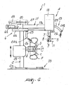
- the reference numeral 1 generally designates a machine for fitting and removing tires and rims of wheels for vehicles
- the machine 1 comprises a frame 2 for supporting means 3 for coupling and turning a rim C, on/from which it is necessary to fit/remove a tire P, about a rotation axis R, and a working assembly 4 that is supported so that it can move by the frame 2 and is provided with a working head 5 for fitting and removing the rim C and the tire P.
- the head 5 is associated with first actuation means 6 for translational actuation in a direction that is parallel to the rotation axis R, which are constituted by a first actuator 6a that acts in a horizontal direction and is associated with said head
- the frame 2 is constituted by a footing 2a from which a vertical column 2b rises; the means 3 are associated so that they can slide along said column, and the rotation axis R is arranged horizontally.
- the machine 1 could be provided with a differently structured frame 2 and/or the rotation axis R could be arranged substantially vertically or otherwise incline.
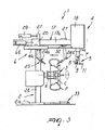
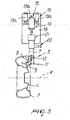
- the head 5 is provided with a pusher 7 that is substantially tubular, is arranged vertically above the supporting means 3 and transversely to the rotation axis R, and is provided with an abutment surface 8 that is associable with a side of the tire P during removal thereof ( Figure 4).
- the pusher 7 has an open lower end.
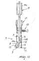
- the head 5 further has at least one tool 9 for removing the tire P from the rim C, which is associated with second actuation means 10 that are suitable to allow its movement alternately between an inactive configuration, in which it is contained at least partially inside the pusher 7, and an active configuration, in which it protrudes partially from said pusher ( Figure 11).
- the tool 9 is completely accommodated within the pusher 7 in the inactive configuration ( Figure 10).
- the head 5 is conveniently provided with a supporting tool 11 for supporting the tire P, which acts during removal in order to move said tire away from the rim C ( Figure 7) and during fitting in order to position it on said rim ( Figures 8 and 9).
- the tool 11 is constituted by a plate that is rigidly associated at the lower end of the pusher 7 and cantilevers out on the opposite side of the abutment surface 8.
- the abutment surface 8 is shaped so as to protrude toward the tire P to be removed, so as to form a wedge-shaped element.
- the end 9a of the tool 9 that is directed toward the tire P is hook-shaped and suitable to abut against the inner surface of the bead of the tire.
- the second actuation means 10 comprise guiding means 12 for guiding the tool 9, which are constituted by two pairs of through slots 13 that are formed on the side wall of the pusher 7, preferably monolithically with and at the internal lateral surface of the pusher 7; the slots 13 of each pair are mutually identical and are arranged so as to face each other in a mirror-symmetrical fashion on opposite sides of said pusher.
- Each pair of slots 13 is associated with a respective pivot 14 (in particular 14a, 14b), which is arranged transversely with respect to the tool 9, is associated or connected with said tool, and has each end arranged at, or associated so that it can slide along a corresponding slot 13.
- Each slot 13 is constituted by a plurality of segments or portions that are mutually connected so as to form a broken line path.
- the profiles of the slots 13 are sized so as to guide the tool 9 in a combined (rotary and translational) motion between the inactive configuration and the active configuration.
- the two pivots 14a and 14b are arranged respectively proximate to the centerline of the tool 9 and to the end 9b that lies opposite the hook-shaped end 9a, the end 9b being fork-shaped.
- the second actuation means 10 comprise motion means 15 for producing an alternating rectilinear motion, which are constituted by a second actuator 15a that uses a fluid medium and acts in a vertical direction, and are associated with the tool 9 by means of the interposition of a linkage 16.
- the ends of the linkage 16 are respectively articulated to the lower end of the stem of the second actuator 15a and to the end 9b of the tool 9 at the pivot 14b.
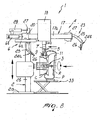
- the frame 2 comprises a guiding element 17, which is constituted by a profiled element that has an I-shaped transverse cross-section, is arranged so that its wings are vertical, and protrudes parallel to the rotation axis R from the upper portion of the column 2b.
- the assembly 4 comprises a slider 18 for supporting the head 5, which is associated so that it can slide along the guiding element 17 and comprises a first portion and a second portion, the first portion being associated with said guiding element, the second portion supporting the head 5 and being associated with the first portion so that it can move.
- the second portion of the slider 18 supports the second actuator 15a.
- the machine 1 further comprises third actuation means 19 for actuating the head 5 with a vertical translational motion, which are constituted by two third actuators 19a that use a fluid medium, act at right angles to the rotation axis R, and are interposed between said portions of the slider 18 and on opposite sides of the second actuator 15a.
- third actuation means 19 for actuating the head 5 with a vertical translational motion which are constituted by two third actuators 19a that use a fluid medium, act at right angles to the rotation axis R, and are interposed between said portions of the slider 18 and on opposite sides of the second actuator 15a.
- the assembly 4 further comprises an additional slider 20, which is associated so that it can slide along the guiding element 17 and is interposed between the slider 18 and the column 2b.
- the first actuation means 6 comprise a first additional fluid-medium actuator 6b, which acts in a direction that is; parallel to the rotation axis R and is interposed between the guiding element 17 and the additional slider 20; the actuation of the first additional actuator 6b produces the translational motion of the additional slider 20 with respect to the guiding element 17 and therefore with respect to the frame 2.
- the first actuator 6a is instead interposed between the additional slider 20 and the slider 18; actuation of the first actuator 6a produces the translational motion of the slider 18 with respect to the additional slider 20.
- the sliders 18 and 20 are associated so that they can slide along a same wing 17a of the guiding element 17.
- the assembly 4 is provided with conventional means 21 for rotating the head 5 about a vertical axis that substantially coincides with the longitudinal axis of said head; such means allow to arrange the tool 11 adjacent to both sides of the tire P ( Figures 10 and 11).
- the rotation means 21 are of the manual type, but alternative embodiments in which said means are actuated automatically are not excluded.
- the rotation means 21 are provided with a device 22 for stopping the rotation of the head 5, which allows to lock said head in two mutually angularly offset configurations.
- the assembly 4 comprises means 23 for separating the tire P from the rim C, which perform the operation conventionally known as bead breaking.
- the separation means 23 are constituted by two pushers 24, which are associated so that they can slide along the guiding element 17 on opposite sides of the tire P being treated and are constituted by respective arms 25 for supporting disks 26 that are keyed freely on said arms and can be associated with the sides of the tire P.
- the pusher 24a cooperates with the side of the tire P that is directed toward the column 2b, while the pusher 24b is suitable to cooperate with the side of the tire P that is directed toward the free end of the guiding element 17.
- Each arm 25 is fitted on a corresponding support 27 that is associated so that it can slide along the wing of the guiding element 17 that lies opposite the wing 17a along which the sliders 18 and 20 are arranged.
- the arm 25 of the pusher 24a is rigidly coupled to the corresponding support 27, while the arm 25 of the pusher 24b is associated with the corresponding support 27 so that it can oscillate about an axis that is horizontal and transverse with respect to said element between a configuration that is adjacent to the rim C and a configuration that is spaced from said rim.
- Each arm 25 of the pushers 24a and 24b is associated with an actuator 29, which is suitable to actuate respectively the translational motion along the guiding element 17 and the translational motion along said element combined with rotation.
- the means 3 comprise a flange 30 for supporting the rim C, which is associated with conventional motor means, not shown in the figures, which actuate its rotation about the rotation axis R, a reference rod 31 on which the rim C is fitted, said rod protruding from the center of the flange 30 in a horizontal direction and having a threaded end, and a threaded locking element 32, which couples on the rod 31 and clamps the rim C being processed.
- the means 3 are associated with conventional actuation means, not shown in the figures, which produce their translational motion along the column 2b.
- the machine 1 is further provided with means 33 for lifting and lowering the rim C and the tire P for loading and unloading the means 3, said means not being shown in detail because they are of a conventional type.
- the machine 1 is associated with conventional actuation and control means, not shown in the figures, which allow the operator to actuate its operation and adjust its movements.
- the bead-breaking step allows to separate the beads of the tire P from the corresponding seats on the rim C.
- the pushers 24 move away from the region adjacent to said tire and the pusher 24b moves to a spaced configuration so as not to interfere with the head 5.
- the head 5 is arranged at a suitable distance from the rim C, depending on the dimensional and constructive characteristics of said rim.
- the head 5, with the tool 9 in the inactive configuration, is then moved toward the tire P by means of the actuator 6a so that the abutment surface 8 abuts against the side of the tire P, moving it away from the rim C ( Figure 4) and forming a passage for the tool 9.
- the head 5 is placed proximate to the column 2b, so that the tool 11 grips the corresponding bead of the tire P.
- the opening of the first actuator 6a causes the head 5 to push the tire P, supported by the tool 11, away from the rim C, so as to completely separate said tire ( Figure 7); in this work step, the pusher 24a can cooperate in removing the tire P from the rim C.
Landscapes
- Engineering & Computer Science (AREA)
- Mechanical Engineering (AREA)
- Tires In General (AREA)
- Automatic Assembly (AREA)
- Tyre Moulding (AREA)
- Automobile Manufacture Line, Endless Track Vehicle, Trailer (AREA)
- Testing Of Balance (AREA)
Applications Claiming Priority (2)
| Application Number | Priority Date | Filing Date | Title |
|---|---|---|---|
| ITMO20030132 | 2003-05-09 | ||
| IT000132A ITMO20030132A1 (it) | 2003-05-09 | 2003-05-09 | Macchina per il montaggio e lo smontaggio di pneumatici e cerchi di ruote per veicoli. |
Publications (2)
| Publication Number | Publication Date |
|---|---|
| EP1475252A1 EP1475252A1 (en) | 2004-11-10 |
| EP1475252B1 true EP1475252B1 (en) | 2007-11-14 |
Family
ID=30012732
Family Applications (1)
| Application Number | Title | Priority Date | Filing Date |
|---|---|---|---|
| EP04009610A Expired - Lifetime EP1475252B1 (en) | 2003-05-09 | 2004-04-22 | Machine for fitting and removing tires and wheel rims for vehicles |
Country Status (6)
| Country | Link |
|---|---|
| US (1) | US7048026B2 (it) |
| EP (1) | EP1475252B1 (it) |
| JP (1) | JP4646544B2 (it) |
| CN (1) | CN100404288C (it) |
| DE (1) | DE602004009988T2 (it) |
| IT (1) | ITMO20030132A1 (it) |
Cited By (1)
| Publication number | Priority date | Publication date | Assignee | Title |
|---|---|---|---|---|
| CN104827836A (zh) * | 2014-02-07 | 2015-08-12 | 西卡姆有限公司 | 轮胎拆装机 |
Families Citing this family (46)
| Publication number | Priority date | Publication date | Assignee | Title |
|---|---|---|---|---|
| ITRE20040049A1 (it) * | 2004-05-06 | 2004-08-06 | Corghi Spa | Dispositivo automatico per lo smontaggio ed il montaggio dei pneumatici |
| ITMI20041570A1 (it) | 2004-07-30 | 2004-10-30 | Ennio Galbiati | "macchina smontagomme a singolo utensile plurifunzione" |
| ITVR20050037A1 (it) * | 2005-03-23 | 2006-09-24 | Butler Eng & Marketing | Utensile per il montaggio/smontaggio automatico di un pneumatico su/da un cerchione |
| ITRE20050079A1 (it) * | 2005-07-11 | 2007-01-12 | Corghi Spa | Metodo e dispositivo per lo smontaggio di pneumatici autoportanti |
| US7621311B2 (en) * | 2005-10-05 | 2009-11-24 | Android Industries Llc | Tire-wheel assembly adjuster |
| US7343955B2 (en) | 2005-12-28 | 2008-03-18 | Hennessy Industries, Inc. | Tire changing machine |
| US7438109B2 (en) * | 2005-12-30 | 2008-10-21 | Hennessy Industries, Inc. | Tire changer |
| ITMO20060275A1 (it) * | 2006-09-08 | 2008-03-09 | Giuliano Spa | Macchina per il montaggio e lo smontaggio di ruote di veicoli |
| ITMO20060273A1 (it) * | 2006-09-08 | 2008-03-09 | Giuliano Spa | Macchina per il montaggio e lo smontaggio di pneumatici e cerchi di ruote per veicoli |
| DE502007002397D1 (de) * | 2007-01-15 | 2010-02-04 | Snap On Equipment S R L A Unic | Vorrichtung zum Montieren oder Demontieren eines Luftreifens von einer Felge eines Fahrzeugrades |
| ITMO20070350A1 (it) * | 2007-11-21 | 2009-05-22 | Giuliano Spa | Macchina per il montaggio e lo smontaggio di pneumatici di ruote per veicoli |
| US8307874B1 (en) | 2008-01-25 | 2012-11-13 | Hunter Engineering Company | Tire changing method and machine with angularly positionable drive axis |
| JP2009227006A (ja) * | 2008-03-19 | 2009-10-08 | Onodani Kiko Kk | タイヤ着脱装置のタイヤビード案内装置 |
| JP5563742B2 (ja) * | 2008-03-19 | 2014-07-30 | 小野谷機工株式会社 | タイヤ着脱装置のマウントプレス装置 |
| ES2356039T3 (es) * | 2008-04-17 | 2011-04-04 | Snap-On Equipment Srl A Unico Socio | Procedimiento y aparato para montar y desmontar un neumático de vehículo a motor. |
| IT1392089B1 (it) * | 2008-10-13 | 2012-02-09 | Giuliano S P A Ora Giuliano Group S P A | Testa operativa per lo smontaggio ed il montaggio di pneumatici di ruote per veicoli |
| US8333228B1 (en) | 2008-10-15 | 2012-12-18 | Hennessy Industries, Inc. | Tire changer with attached inflation cage |
| US8443865B2 (en) * | 2009-08-21 | 2013-05-21 | Hennessy Industries, Inc. | Wheel clamping apparatus and method |
| DE102010017031A1 (de) * | 2010-05-19 | 2011-11-24 | Schenck Rotec Gmbh | Vorrichtung und Verfahren zur Änderung der Drehwinkellage eines Luftreifens auf einer Felge |
| IT1402585B1 (it) | 2010-10-22 | 2013-09-13 | Maioli | Macchina smontagomme. |
| EP2444260B1 (en) * | 2010-10-25 | 2013-03-27 | Snap-on Equipment Srl a unico socio | Synchronization of tyre bead breaker tools |
| US8973640B1 (en) | 2010-12-07 | 2015-03-10 | Hunter Engineering Company | Demount tool assembly and methods for automated tire changer machine |
| IT1403494B1 (it) | 2010-12-23 | 2013-10-17 | Butler Eng & Marketing | Dispositivo di smontaggio del secondo tallone di un pneumatico da un cerchione e relativo metodo di smontaggio |
| US20120222823A1 (en) * | 2011-03-02 | 2012-09-06 | Onodani Machine Co., Ltd. | Tire mounting and demounting machine, tire mounting method and tire demounting method |
| ITMO20110119A1 (it) * | 2011-05-20 | 2012-11-21 | Giuliano Group Spa | Macchina per il montaggio e lo smontaggio di pneumatici di ruote per veicoli |
| ITVR20110112A1 (it) * | 2011-05-20 | 2012-11-21 | Butler Eng & Marketing | Dispositivo di smontaggio automatico di un pneumatico da un cerchione e macchina dotata di tale dispositivo |
| ITMO20110316A1 (it) * | 2011-12-02 | 2013-06-03 | Giuliano Group Spa | Testa operativa per lo smontaggio ed il montaggio di pneumatici di ruote per veicoli |
| ITMO20120009A1 (it) * | 2012-01-16 | 2013-07-17 | Gino Ferrari | Dispositivo estrattore per macchine smontagomme |
| WO2015153001A1 (en) * | 2014-04-03 | 2015-10-08 | Bridgestone Americas Tire Operations, Llc | Tire bead fitter for tire mounting machine |
| EP2987661B1 (en) * | 2014-07-28 | 2019-10-23 | Butler Engineering & Marketing S.p.A. | Device for assembling-disassembling a tyred wheel, as well as machine comprising such a device |
| DE202014008932U1 (de) * | 2014-11-11 | 2016-03-02 | Snap-On Equipment Srl A Unico Socio | Reifenmontage- und -demontagewerkzeug |
| JP6165183B2 (ja) * | 2015-01-23 | 2017-07-19 | 株式会社サカモト | ホイール装着方法、ホイール装着装置およびタイヤへのホイール着脱装置 |
| CN104890458B (zh) * | 2015-06-16 | 2016-10-19 | 毕作亮 | 轮胎校正机 |
| IT201600071778A1 (it) * | 2016-07-08 | 2018-01-08 | Butler Eng And Marketing S P A | Gruppo di stallonamento di una ruota gommata e/o di spinta di una porzione di un pneumatico di una ruota gommata |
| CN106080060B (zh) * | 2016-07-14 | 2017-07-28 | 哈尔滨工业大学 | 一种用于轮胎检测的扒胎机构 |
| EP3315331B1 (en) * | 2016-10-18 | 2019-04-03 | NEXION S.p.A. | Tyre changing machine |
| IT201600111370A1 (it) * | 2016-11-04 | 2018-05-04 | Nexion Spa | Apparato per montare e smontare uno pneumatico |
| CN107187282B (zh) * | 2017-05-02 | 2023-07-18 | 昆明理工大学 | 一种汽车轮胎轮毂拆卸装置 |
| IT201800020740A1 (it) * | 2018-12-21 | 2020-06-21 | Gino Ferrari | Macchina smontagomme universale |
| CN112477510B (zh) * | 2019-09-11 | 2025-02-07 | 张卫 | 车轮维护装置 |
| CN110843431B (zh) * | 2019-12-03 | 2020-12-22 | 扬州瑞顺投资咨询有限公司 | 一种轮胎自动剥离外胎设备 |
| CN110816161B (zh) * | 2019-12-05 | 2025-03-11 | 青岛港国际股份有限公司 | 一种轮胎吊用轮胎更换装置 |
| IT202000002920A1 (it) * | 2020-02-13 | 2021-08-13 | Butler Eng And Marketing S P A Abbreviabile In Butler S P A | Apparecchiatura e procedimento per il montaggio e smontaggio di pneumatici |
| US11986947B2 (en) * | 2020-05-11 | 2024-05-21 | Automated Tire, Inc. | Autonomous traverse tire changing bot, autonomous tire changing system, and method therefor |
| US20230417617A1 (en) | 2022-06-22 | 2023-12-28 | Automated Tire, Inc. | Autonomous tire and wheel balancer, method therefor and robotic automotive service system |
| CN115648863A (zh) * | 2022-11-28 | 2023-01-31 | 池学建 | 摇摆式轮胎拆胎机及其工作方法 |
Family Cites Families (8)
| Publication number | Priority date | Publication date | Assignee | Title |
|---|---|---|---|---|
| CN2291328Y (zh) * | 1997-01-11 | 1998-09-16 | 张秉君 | 汽车轮胎拆装机 |
| IT1310170B1 (it) * | 1999-02-04 | 2002-02-11 | Giuliano Srl | Macchina per il montaggio e lo smontaggio di pneumatici di tipospeciale |
| IT1310590B1 (it) * | 1999-05-14 | 2002-02-19 | Giuliano Srl | Stazione multifunzionale per il montaggio e lo smontaggio dipneumatici sia di tipo convenzionale sia speciale. |
| IT1319475B1 (it) * | 2000-08-03 | 2003-10-10 | Corghi Spa | Dispositivo automatico per lo smontaggio ed il montaggio deipneumatici, e macchine smontagomme cosi' attrezzate |
| IT1319437B1 (it) * | 2000-10-24 | 2003-10-10 | Elettromeccaniche S I C E Soc | Macchina smontagomme |
| JP3626088B2 (ja) * | 2000-11-09 | 2005-03-02 | 小野谷機工株式会社 | 自動車タイヤ取外し方法、およびタイヤ取外し装置 |
| ITVR20010124A1 (it) * | 2001-11-22 | 2003-05-22 | Butler Enrineering & Marketing | Testa di stallonatura con unghia per il montaggio/smontaggio di un pneumatico per macchina smontagomme. |
| ITRE20020068A1 (it) * | 2002-09-13 | 2004-03-14 | Corghi Spa | Dispositivo automatico semplificato per lo smontaggio |
-
2003
- 2003-05-09 IT IT000132A patent/ITMO20030132A1/it unknown
-
2004
- 2004-04-22 EP EP04009610A patent/EP1475252B1/en not_active Expired - Lifetime
- 2004-04-22 DE DE602004009988T patent/DE602004009988T2/de not_active Expired - Lifetime
- 2004-04-26 US US10/831,148 patent/US7048026B2/en not_active Expired - Fee Related
- 2004-04-30 CN CNB2004100374256A patent/CN100404288C/zh not_active Expired - Fee Related
- 2004-05-07 JP JP2004138929A patent/JP4646544B2/ja not_active Expired - Fee Related
Cited By (1)
| Publication number | Priority date | Publication date | Assignee | Title |
|---|---|---|---|---|
| CN104827836A (zh) * | 2014-02-07 | 2015-08-12 | 西卡姆有限公司 | 轮胎拆装机 |
Also Published As
| Publication number | Publication date |
|---|---|
| ITMO20030132A0 (it) | 2003-05-09 |
| US7048026B2 (en) | 2006-05-23 |
| ITMO20030132A1 (it) | 2004-11-10 |
| JP2004331063A (ja) | 2004-11-25 |
| DE602004009988D1 (de) | 2007-12-27 |
| DE602004009988T2 (de) | 2008-09-18 |
| JP4646544B2 (ja) | 2011-03-09 |
| CN100404288C (zh) | 2008-07-23 |
| US20040221964A1 (en) | 2004-11-11 |
| CN1550361A (zh) | 2004-12-01 |
| EP1475252A1 (en) | 2004-11-10 |
Similar Documents
| Publication | Publication Date | Title |
|---|---|---|
| EP1475252B1 (en) | Machine for fitting and removing tires and wheel rims for vehicles | |
| EP1897708B1 (en) | Machine for fitting and removing tyres and wheel rims for vehicles | |
| US8973640B1 (en) | Demount tool assembly and methods for automated tire changer machine | |
| EP2962876B1 (en) | Machine and method for fitting and removing a tyre | |
| EP3319820B1 (en) | A tire demounting device | |
| EP2362836B1 (en) | Device for fitting and removing tyres | |
| EP2062752B1 (en) | Machine for fitting and removing wheel tyres for vehicles | |
| EP1916125B1 (en) | Operating head for a tyre-removal machine and associated tyre-removal machine | |
| JP2013116728A (ja) | 車両用の車輪のタイヤを取り外しおよび取り付けるための作業ヘッド | |
| EP1625954B1 (en) | Tyre-removal machine with single multifunctional tool | |
| EP1844959B1 (en) | Method and machine for removing a tyre fitted with a rigid inner run-flat ring | |
| HK1071110A (en) | Machine for fitting and removing tires and wheel rims for vehicles | |
| US8381791B2 (en) | Device for lifting a bottom side wall of a tyre in a tyre removing machine | |
| EP3069905B1 (en) | Operating head for a tyre changer machine | |
| EP2281699B1 (en) | Unit for bead breaking in tyre changing machines | |
| EP2804771A1 (en) | Tyre bead extreaction device for tire - changing machines | |
| EP1479539B1 (en) | Machine for fitting and removing tires and rims of vehicle wheels | |
| EP4532231B1 (en) | Device for fitting/removing tires | |
| HK1067878A (en) | Machine for fitting and removing tires and wheel rims for vehicles | |
| CN117597244A (zh) | 用于安装/拆卸轮胎的装置 | |
| ITBO20130384A1 (it) | Dispositivo e metodo per stallonare ruote dotate di uno pneumatico accoppiato a un cerchione. | |
| ITBO20130383A1 (it) | Dispositivo e metodo per stallonare ruote dotate di uno pneumatico accoppiato a un cerchione. |
Legal Events
| Date | Code | Title | Description |
|---|---|---|---|
| PUAI | Public reference made under article 153(3) epc to a published international application that has entered the european phase |
Free format text: ORIGINAL CODE: 0009012 |
|
| AK | Designated contracting states |
Kind code of ref document: A1 Designated state(s): AT BE BG CH CY CZ DE DK EE ES FI FR GB GR HU IE IT LI LU MC NL PL PT RO SE SI SK TR |
|
| AX | Request for extension of the european patent |
Extension state: AL HR LT LV MK |
|
| RAP1 | Party data changed (applicant data changed or rights of an application transferred) |
Owner name: GIULIANO S.P.A. |
|
| 17P | Request for examination filed |
Effective date: 20050419 |
|
| REG | Reference to a national code |
Ref country code: HK Ref legal event code: DE Ref document number: 1071110 Country of ref document: HK |
|
| AKX | Designation fees paid |
Designated state(s): BE DE FR IT |
|
| GRAP | Despatch of communication of intention to grant a patent |
Free format text: ORIGINAL CODE: EPIDOSNIGR1 |
|
| GRAS | Grant fee paid |
Free format text: ORIGINAL CODE: EPIDOSNIGR3 |
|
| GRAA | (expected) grant |
Free format text: ORIGINAL CODE: 0009210 |
|
| AK | Designated contracting states |
Kind code of ref document: B1 Designated state(s): BE DE FR IT |
|
| REF | Corresponds to: |
Ref document number: 602004009988 Country of ref document: DE Date of ref document: 20071227 Kind code of ref document: P |
|
| ET | Fr: translation filed | ||
| PLBE | No opposition filed within time limit |
Free format text: ORIGINAL CODE: 0009261 |
|
| STAA | Information on the status of an ep patent application or granted ep patent |
Free format text: STATUS: NO OPPOSITION FILED WITHIN TIME LIMIT |
|
| 26N | No opposition filed |
Effective date: 20080815 |
|
| REG | Reference to a national code |
Ref country code: DE Ref legal event code: R082 Ref document number: 602004009988 Country of ref document: DE Representative=s name: DREISS PATENTANWAELTE, DE |
|
| REG | Reference to a national code |
Ref country code: DE Ref legal event code: R081 Ref document number: 602004009988 Country of ref document: DE Owner name: GIULIANO GROUP S.P.A., IT Free format text: FORMER OWNER: GIULIANO S.P.A., CORREGGIO, IT Effective date: 20110718 Ref country code: DE Ref legal event code: R082 Ref document number: 602004009988 Country of ref document: DE Representative=s name: DREISS PATENTANWAELTE PARTG MBB, DE Effective date: 20110718 |
|
| REG | Reference to a national code |
Ref country code: FR Ref legal event code: CD Ref country code: FR Ref legal event code: CA |
|
| REG | Reference to a national code |
Ref country code: HK Ref legal event code: WD Ref document number: 1071110 Country of ref document: HK |
|
| REG | Reference to a national code |
Ref country code: FR Ref legal event code: PLFP Year of fee payment: 12 |
|
| PGFP | Annual fee paid to national office [announced via postgrant information from national office to epo] |
Ref country code: DE Payment date: 20150429 Year of fee payment: 12 |
|
| PGFP | Annual fee paid to national office [announced via postgrant information from national office to epo] |
Ref country code: BE Payment date: 20150427 Year of fee payment: 12 Ref country code: FR Payment date: 20150417 Year of fee payment: 12 |
|
| PG25 | Lapsed in a contracting state [announced via postgrant information from national office to epo] |
Ref country code: BE Free format text: LAPSE BECAUSE OF NON-PAYMENT OF DUE FEES Effective date: 20160430 |
|
| REG | Reference to a national code |
Ref country code: DE Ref legal event code: R119 Ref document number: 602004009988 Country of ref document: DE |
|
| REG | Reference to a national code |
Ref country code: FR Ref legal event code: ST Effective date: 20161230 |
|
| PG25 | Lapsed in a contracting state [announced via postgrant information from national office to epo] |
Ref country code: FR Free format text: LAPSE BECAUSE OF NON-PAYMENT OF DUE FEES Effective date: 20160502 Ref country code: DE Free format text: LAPSE BECAUSE OF NON-PAYMENT OF DUE FEES Effective date: 20161101 |
|
| P01 | Opt-out of the competence of the unified patent court (upc) registered |
Effective date: 20230527 |
|
| PGFP | Annual fee paid to national office [announced via postgrant information from national office to epo] |
Ref country code: IT Payment date: 20230421 Year of fee payment: 20 |