EP1475509A1 - Antriebs- und Verriegelungsaggregat - Google Patents
Antriebs- und Verriegelungsaggregat Download PDFInfo
- Publication number
- EP1475509A1 EP1475509A1 EP04018818A EP04018818A EP1475509A1 EP 1475509 A1 EP1475509 A1 EP 1475509A1 EP 04018818 A EP04018818 A EP 04018818A EP 04018818 A EP04018818 A EP 04018818A EP 1475509 A1 EP1475509 A1 EP 1475509A1
- Authority
- EP
- European Patent Office
- Prior art keywords
- drive
- bearing
- rotary column
- column tube
- locking unit
- Prior art date
- Legal status (The legal status is an assumption and is not a legal conclusion. Google has not performed a legal analysis and makes no representation as to the accuracy of the status listed.)
- Granted
Links
- 230000008878 coupling Effects 0.000 claims abstract description 44
- 238000010168 coupling process Methods 0.000 claims abstract description 44
- 238000005859 coupling reaction Methods 0.000 claims abstract description 44
- 230000000903 blocking effect Effects 0.000 claims abstract description 38
- 230000002349 favourable effect Effects 0.000 description 10
- 238000003825 pressing Methods 0.000 description 10
- 230000005540 biological transmission Effects 0.000 description 7
- 238000004519 manufacturing process Methods 0.000 description 6
- 238000012544 monitoring process Methods 0.000 description 6
- 238000003860 storage Methods 0.000 description 6
- 238000010276 construction Methods 0.000 description 5
- 238000013461 design Methods 0.000 description 5
- NJPPVKZQTLUDBO-UHFFFAOYSA-N novaluron Chemical compound C1=C(Cl)C(OC(F)(F)C(OC(F)(F)F)F)=CC=C1NC(=O)NC(=O)C1=C(F)C=CC=C1F NJPPVKZQTLUDBO-UHFFFAOYSA-N 0.000 description 4
- 239000004033 plastic Substances 0.000 description 4
- 230000009467 reduction Effects 0.000 description 4
- 241000591215 Acraea andromacha Species 0.000 description 3
- 230000004888 barrier function Effects 0.000 description 3
- 238000003780 insertion Methods 0.000 description 3
- 230000037431 insertion Effects 0.000 description 3
- 230000010354 integration Effects 0.000 description 3
- 230000002093 peripheral effect Effects 0.000 description 3
- 238000006073 displacement reaction Methods 0.000 description 2
- 238000009434 installation Methods 0.000 description 2
- 229910001220 stainless steel Inorganic materials 0.000 description 2
- 239000010935 stainless steel Substances 0.000 description 2
- 101100293261 Mus musculus Naa15 gene Proteins 0.000 description 1
- 241000054879 Pteris denticulata Species 0.000 description 1
- 229910000831 Steel Inorganic materials 0.000 description 1
- LYKJEJVAXSGWAJ-UHFFFAOYSA-N compactone Natural products CC1(C)CCCC2(C)C1CC(=O)C3(O)CC(C)(CCC23)C=C LYKJEJVAXSGWAJ-UHFFFAOYSA-N 0.000 description 1
- 230000006835 compression Effects 0.000 description 1
- 238000007906 compression Methods 0.000 description 1
- 230000001143 conditioned effect Effects 0.000 description 1
- 238000002788 crimping Methods 0.000 description 1
- 238000011161 development Methods 0.000 description 1
- 230000000694 effects Effects 0.000 description 1
- 230000005489 elastic deformation Effects 0.000 description 1
- 230000005611 electricity Effects 0.000 description 1
- 238000005516 engineering process Methods 0.000 description 1
- 210000001061 forehead Anatomy 0.000 description 1
- 239000011521 glass Substances 0.000 description 1
- 230000005484 gravity Effects 0.000 description 1
- 238000011078 in-house production Methods 0.000 description 1
- 238000009413 insulation Methods 0.000 description 1
- 230000007246 mechanism Effects 0.000 description 1
- 238000000926 separation method Methods 0.000 description 1
- 239000010959 steel Substances 0.000 description 1
- 238000012549 training Methods 0.000 description 1
- 238000012546 transfer Methods 0.000 description 1
- 230000007704 transition Effects 0.000 description 1
- 238000003466 welding Methods 0.000 description 1
Images


Classifications
-
- E—FIXED CONSTRUCTIONS
- E06—DOORS, WINDOWS, SHUTTERS, OR ROLLER BLINDS IN GENERAL; LADDERS
- E06B—FIXED OR MOVABLE CLOSURES FOR OPENINGS IN BUILDINGS, VEHICLES, FENCES OR LIKE ENCLOSURES IN GENERAL, e.g. DOORS, WINDOWS, BLINDS, GATES
- E06B11/00—Means for allowing passage through fences, barriers or the like, e.g. stiles
- E06B11/08—Turnstiles; Gates for control of entry or exit of persons, e.g. in supermarkets
- E06B11/085—Turnstiles; Gates for control of entry or exit of persons, e.g. in supermarkets non-rotary or with a limited angle of rotation, e.g. 90°
-
- E—FIXED CONSTRUCTIONS
- E05—LOCKS; KEYS; WINDOW OR DOOR FITTINGS; SAFES
- E05F—DEVICES FOR MOVING WINGS INTO OPEN OR CLOSED POSITION; CHECKS FOR WINGS; WING FITTINGS NOT OTHERWISE PROVIDED FOR, CONCERNED WITH THE FUNCTIONING OF THE WING
- E05F15/00—Power-operated mechanisms for wings
- E05F15/60—Power-operated mechanisms for wings using electrical actuators
- E05F15/603—Power-operated mechanisms for wings using electrical actuators using rotary electromotors
- E05F15/611—Power-operated mechanisms for wings using electrical actuators using rotary electromotors for swinging wings
- E05F15/614—Power-operated mechanisms for wings using electrical actuators using rotary electromotors for swinging wings operated by meshing gear wheels, one of which being mounted at the wing pivot axis; operated by a motor acting directly on the wing pivot axis
-
- E—FIXED CONSTRUCTIONS
- E05—LOCKS; KEYS; WINDOW OR DOOR FITTINGS; SAFES
- E05Y—INDEXING SCHEME ASSOCIATED WITH SUBCLASSES E05D AND E05F, RELATING TO CONSTRUCTION ELEMENTS, ELECTRIC CONTROL, POWER SUPPLY, POWER SIGNAL OR TRANSMISSION, USER INTERFACES, MOUNTING OR COUPLING, DETAILS, ACCESSORIES, AUXILIARY OPERATIONS NOT OTHERWISE PROVIDED FOR, APPLICATION THEREOF
- E05Y2600/00—Mounting or coupling arrangements for elements provided for in this subclass
- E05Y2600/50—Mounting methods; Positioning
- E05Y2600/52—Toolless
- E05Y2600/522—Axial stacking
-
- E—FIXED CONSTRUCTIONS
- E05—LOCKS; KEYS; WINDOW OR DOOR FITTINGS; SAFES
- E05Y—INDEXING SCHEME ASSOCIATED WITH SUBCLASSES E05D AND E05F, RELATING TO CONSTRUCTION ELEMENTS, ELECTRIC CONTROL, POWER SUPPLY, POWER SIGNAL OR TRANSMISSION, USER INTERFACES, MOUNTING OR COUPLING, DETAILS, ACCESSORIES, AUXILIARY OPERATIONS NOT OTHERWISE PROVIDED FOR, APPLICATION THEREOF
- E05Y2900/00—Application of doors, windows, wings or fittings thereof
- E05Y2900/40—Application of doors, windows, wings or fittings thereof for gates
Definitions
- the invention relates to a drive and locking unit for a person sluice to the person passage control, with at least one in an assembly position preferably rotatable substantially vertical axis of rotation stored and by means of a, designed as a brake, unlockable locking device in at least one direction of rotation lockable against rotation or releasable for rotation Blocking element, for example a pivoting wing, in particular a door leaf or a blocking arm, by means of a drive from a person passage blocking Locked position in a person passageway releasing Rotary position is actuated.
- a drive and locking unit of the beginning mentioned type is for example from EP 0 622 514 or from DE 43 14 026 A1 become known.
- the coupling can be a preferably the Vertikalalkraftabstützungs workede front end of the rotary column tube rotatable and optionally axially fixed in the same recorded coupling sleeve with an internal toothing and a rotatable with the associated bearing pin and optionally axially fixed connected hub part comprising a in the internal toothing of the coupling sleeve engages positively Having external teeth.
- a coupling makes it possible in a favorable way, a variety of different use designed pivoting wing arrangements, without at the same time the assigned storage and operating units would have to be changed. This can be done Achieve manufacturing and cost advantages. Furthermore allows Such a coupling a very precise storage of the rotary column tube.
- the person lock shown in Fig. 1 for a people passage control is here as a double person lock 21 designed and includes four individual person locks 20.
- Each personal lock 20 here also has a blocking element unit designated drive and locking unit 26 with a rotatably mounted about a rotation axis 28 and by means of an unlockable locking device 29 in at least one direction of rotation 36 lockable against rotation or for rotation releasable blocking element 24, here in shape a U-shaped tube bracket 25 on.
- Such blocking elements is not limited, but that For example, as a locking elements and door or other type locking arms are used as swing wings. It is understood that the resulting from Fig.
- each blocking element 24 is by means of a drive 32 from a person passage 37, 37 blocking blocking position 35 in one the passageway 37, 37 releasing rotational position operable.
- Each blocking element 24 is fixed to a this carrying rotary column connected, wherein in the embodiment each pipe bracket welded to the associated rotary column tube 27 is.
- each pipe bracket welded to the associated rotary column tube 27 is.
- two person passages 37 are created, the partially or completely by means of the locking elements 24 against a person passage are lockable, wherein the locking elements 24 preferably by the drive 32 in both Turning directions (double arrow 36) are rotatable.
- the entrance is according to a particularly advantageous embodiment released with the help of card readers.
- the end the figures forthcoming drive and locking unit 26 with its locking elements 24 allows a people passage control also and especially with increased personal capacities allows in particular a quick run of each person and is for integration into a higher-level control unit suitable.
- Each personal lock 20 is with a separately manageable or mountable blocking element unit or a Antriebsund Locking unit 26 designed.
- This consists in essentially of three standard units, namely rotary column unit 99, a drive unit 100 and a locking device and monitoring unit 102, in turn, from a Fixing device 81 in the form of a mounting bracket 82 are recorded (Fig. 7).
- the rotary column unit consists of the rotary column tube 27 with the attached thereto Locking element 24.
- the drive unit 100 consists essentially from within the rotatable rotary column tube 27 recorded motor 33 with gear 34, wherein the rotor of the Motor 33 with an active element 42 in the form of a crimp 44 is designed, the a frictional torque transmission from the drive 32 to the rotary column tube 27 and thus mediates the blocking element 24.
- the locking mechanism and monitoring unit 102 consists essentially from an angular and axial error compensating Coupling 40 and a blocking device 29 forming Brake 30, here as an electromagnetically actuated gear coupling 31 is designed and the immediately with a Encoder 72 is provided to control the drive 32.
- a torque support (38) of the drive (32) and a vertical force support (39) of the rotary column tube (27) in the region of in the direction the axis of rotation (28) spaced or pointing away from each other Ends (25, 41) of the rotary column tube (27) takes place.
- a separation of functions can be stable bearing conditions, less wear and tear thereby an over longer time safer and fatigue-free Operation of the drive and locking unit (26) reach.
- this favorable mounting conditions achievable for example, the drive in a simple Way one end in the rotary column tube (27) can be inserted, while on the other side of the rotary column tube (27) the Bearing elements in particular for vertical support can be inserted are.
- two externally inexpensive manufacturable standard units consisting of a drive unit, comprising the engine (33), the transmission (34), preferably as a crimp (44) designed active element (42) and a bearing supporting the rotary column tube (27) and also a locking and monitoring unit, for example comprising a compensating coupling to be provided at another end and as a toothed coupling (31) designed brake (30) and a rotary encoder unit for controlling the drive (32) used become.
- the active element (42) as a crimp (44) with a under exercise of Compressive forces elastically and flexibly deformable contact pressure element (45), which is the one of insertion the crimp (44) and the drive (32) in the rotary column tube (27) enabling position in a frictionally engaged on the inner circumference (43) of the rotary column tube (27) fitting Able to be transferred.
- the assembly or disassembly be further simplified and it can be a special Quiet operation of the drive and locking unit (26) or the passenger lock provided with it by decoupling the engine vibrations of the Reach the rotary column tube (27).
- the contact pressure element (45) designed with a ring (46) made of plastic or rubber is, which objected between in the direction of the axis of rotation (28) Pressure discs (47, 48) is arranged, of which at least a thrust washer (48) by means of a ring (46) in the direction of the axis of rotation (28) passing through the clamping element with simultaneous elastic deformation of the ring (46) in the direction of the other pressure disc (47) is movable.
- This construction is inexpensive to produce and special robust as well as allowing easy replacement of the possibly subject to wear over time Pressing element (45).
- the torque support 38 of the drive 32 and the vertical force support 39 of the rotary column tube 27 take place in Area from in the direction of the axis of rotation 28 of the rotary column tube 27 spaced and pointing away from each other ends 25, 41 of the rotary column tube 27.
- the stator is supported 64 of the motor 33 on the rotationally and axially fixed with this connected bearing pin 50 via a form-releasable Connection to the fastening device 81 mounted in the Condition rotatable and axially resistant.
- the entire drive unit 100 for assembly purposes be plugged into the rotary column tube 27 and to Disassembly purposes, for example, to replace the contact pressure element 45 are pulled out.
- an angular and axial error compensating Coupling 40 is provided at the vertical force support side end 41 of the rotary column tube 27 .
- This consists of one of the lower front end of the rotary column tube 27 in this plug-in Coupling sleeve 52, which has an internal toothing 53 with extending in the direction of the axis of rotation 28 teeth having.
- the External toothing 55 of the hub part 54 also has in Direction of the axis of rotation 28 extending teeth, which with the teeth of the internal teeth 53 of the coupling sleeve 52nd correspond. Due to this tooth arrangement is in certain limits in the direction of the axis of rotation 28 an axial Displacement of the rotary column tube 27 relative to the journal 51 of the hub portion 54 allows so on this Way also an axial error compensation can be achieved.
- the coupling sleeve 52 has at its the insertion end opposite End an annular shoulder on which the end-side end 41 of the rotary column tube 27 during insertion the coupling sleeve 52 abuts in the rotary column tube 27.
- the coupling sleeve 52 and the rotary column tube 27 preferably welded.
- the coupling sleeve 52 is in one piece in the embodiment connected to a ball bearing surface bearing ring bearing 57, that with a matching sliding bearing surfaces having Ring abutment 60 to form a thrust bearing 66 interacts.
- the bearing elements 57 and 60 allow a vertical force support 39 of the rotary column tube 27 with the attached locking element 24 such that the Rotary column tube 27 relative to the annular abutment 60 a Can perform pendulum movement.
- the external teeth 55 of the hub portion 54 and the spherical surfaces the ring bearing 57 designed so coordinated, that the radius center 62 of the spherical part surfaces of Ring bearing 57 with the radius center of the part spherical surface the outer teeth 55 of the hub portion 54 coincide.
- the inner diameter of the central through hole of the Ring bearing 57 and the coupling sleeve 52 are in the embodiment larger than the radial outer peripheral dimensions of Screw head of the clamping screw 49 in such a way that this with the help of a through the said central through-holes by means of an actuating tool pluggable nut can be tightened or loosened.
- the ring abutment 60 is supported on a flange designed bearing element 80 from, here in one piece with the Bearing pin 51 is connected.
- On the outer circumference of the ring flange of the bearing member 80 is a toward the Rotary axis 28 of the rotary column tube 27 and over the circumference arranged longitudinal toothing provided with a matching Internal toothing of a tooth-ring element 67 corresponds, which is accommodated on the annular flange and the due to the splines this opposite in small Limits is axially displaceable.
- the tooth-ring element 67 forms the movable part of a designed as a toothed coupling 31 Brake 30 and has at its from the rotary column tube 27 technological front end a toothing in with radial direction about the axis of rotation 28 extending teeth 69 on.
- These teeth 69 correspond with matching shaped teeth 70 of a rotationally and axially fixedly arranged second tooth-ring element 68, which in turn a receiving leg 85 of the designed as a mounting bracket 82 Fastening device 81 rotationally and axially fixed supported.
- the bearings designed as deep groove ball bearings are based here 78, which turn on the cone-shaped Support bearing element 80 and the rotation of the bearing element 80 and thus of the rotary column tube 27 to the Rotary axis 28 allow and also ultimately to Vertical force support 39 of the rotary column tube 27 with the Blocking element 26 serve.
- the tooth-ring element 67 is spring assisted at non-actuated toothed coupling 31 in the direction of the torque-torque-output side End 25 of the rotary column tube 27 pressed, so that no clutch or brake intervention over the teeth 69 and 70 takes place.
- Be the electromagnets of the toothed coupling 31 with Electricity fed so that conditioned by the training Magnetic field the tooth-ring element 67 against the spring force is pulled against the tooth-ring member 68 until the opposite teeth 69 and 70 of said tooth-ring elements 67 and 68 engage in mutual engagement and in this way, the rotary column tube 27 with the blocking element 24 is locked.
- the control of the drive 32 and the Toothed coupling 31 is effected by means of the rotary encoder 72.
- This consists in the embodiment of an incremental disc 59 made of plastic with radially outwardly extending Longitudinal slots.
- the incremental disk 59 is directly on a rotationally and axially fixed to the peg-like Bearing element 80, thus arranged the hub part 51.
- the incremental disk 59 is on the possibly also integrally connected to the bearing element 80 Pin 73 attached.
- the ring sockets 75 and 76 for fixing the incremental disc 59 of the rotary encoder 72 are also the ring sockets 75 and 76, whose inner diameter is slightly smaller is greater than the outer diameter of the pin 73, so that the bushes 75 and 76 frictionally pressed onto the pin 73 can be.
- the rotary encoder 72 further includes a light barrier 74 with on opposite sides of the Incremental disk 59 arranged light emitting or Light receiving elements.
- Such a brake (30) may conveniently with a plurality of tooth-ring elements (67, 68) facing each other, to enable a mutual intervention To be designed teeth (69, 70), wherein at least one of Tooth-ring elements (67) for at least one further of Tooth-ring elements (68) in the direction of the axis of rotation (28) of the Rotary column tube (27) is arranged axially displaceable to a switchable engagement or removal of the opposite To allow teeth (69, 70), which is characterized by the Tooth-ring elements (67, 68) a rotating and, where appropriate axially fixed, preferably in one piece with one of hineinerstreck end face in the rotary column tube (27) Spigot (51) connected hub part (54) extends, the other end with a rotary encoder (72) for controlling the Drive (32) is rotatably connected.
- the invention relates also a preferably designed as a toothed coupling Brake (30) for a drive and locking unit (26), in particular for a passenger gate for pedestrian access control, with at least one about a rotation axis (28) rotatably mounted and by means of an unlockable Locking device (29) in at least one direction of rotation (36) lockable against rotation or releasable for rotation Locking element (24), for example, a swing wing, in particular a door or a barrier arm, which means a drive (32) from a person passageway (37) locking blocking position (35) in a person passage (37) releasing rotational position is actuated, wherein the Brake (30) directly, preferably rigidly with a rotary encoder (72) for controlling the drive (32) and / or the Brake (30) is connected. It may be appropriate when the hub member (54) at its from the rotary
- a U-shaped mounting bracket 82 designed fastening device 81.
- This has a plate-shaped support or fastening part 83 with extending in both directions in the same direction parallel receiving legs 84 and 85 for releasable recording of the above elements.
- the opposing opening edges 91 of the second Opening 90 is arranged at a distance, each slightly is greater than the distance of the technological End edges of the plate 90, so that these in the final assembly position the rotary column tube 27 with little play positive fit rotationally fixed in the second opening 90 of the receiving leg 84 of the mounting bracket 82 added is.
- the rotary column tube 27 with blocking element 24 is in the in the figures shown assembly end position by means of a Sliding securing element 94 against axial displacement in the direction of the torque-torque-end 25 the rotary column tube 27 securable.
- the shift-securing element 94 one over the handle 96th manually operable sliding latch 95 on which in simple manner, as in particular in Figs.
- the fastening device (81) be designed as a U-shaped mounting bracket (82), a plate-shaped fastening part (83) with it at both ends at an angle of 90 degrees to this extending parallel receiving or mounting legs (84, 85).
- a mounting bracket (82) can expediently be provided with fastening tabs, the opposite the Drehchulenrohr facilityen U-legs extend in opposite directions, with the attachment the mounting bracket expediently at the same time claimedleitiata or passageway limiting elements forming supporting bodies of the security gate takes place.
- a particularly simple and robust mounting option as well as favorable assembly or disassembly conditions with regard to the installation or removal of that at least one blocking element (24) carrying rotary column tube (27) can thereby be achieved that at the torque support side upper end (58) of the rotary column tube (27) provided Bearing element (79) fixed to a fastener (86) connected for the purpose of mounting the rotary column tube (27) through a first opening (88) of the associated Leg (84) of the mounting bracket (82) hin tellsteckbar is and for the purpose of non-rotatable attachment of the bearing element (78) is rotatable in a position in the fastener (86) form-fitting, again detachable with the opening edges (91) of a second (90) opening in the associated leg (84) is connected, wherein the first opening (88) and the second opening (90) with a allowing the passage of at least the bearing element (79) Connection path (92) are interconnected.
- first opening (88) and the second opening (90) is a T- or cross-shaped form common opening (93) and when the fastener (86) with a rectangular plate (87) is designed with a low clearance form-fitting in the second opening (90) is receivable.
- fastener (86) by means of a sliding securing element (94), such as a bar, is securable the for the purpose of an axially fixed attachment or security of the bearing element (79) of a the fastener (86) releasing position into a overlapping position is displaceable.
- a sliding securing element (94) such as a bar
Landscapes
- Engineering & Computer Science (AREA)
- Civil Engineering (AREA)
- Structural Engineering (AREA)
- Power-Operated Mechanisms For Wings (AREA)
- Lock And Its Accessories (AREA)
- Devices For Checking Fares Or Tickets At Control Points (AREA)
- Braking Arrangements (AREA)
- Input Circuits Of Receivers And Coupling Of Receivers And Audio Equipment (AREA)
- Vending Machines For Individual Products (AREA)
Abstract
Description
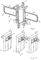
- Fig. 1
- eine dreidimensionale Ansicht von zwei Personenschleusen, welche hier zu einer gemeinsamen Personenschleuse mit drei Standsäulen zusammengefasst sind, wobei die mittlere Standsäule zwei Antriebs- und Verriegelungsaggregate aufweist, die jeweils mit einem Drehsäulenrohr und einem daran befestigten Sperrelement in Form eines U-förmigen Rohrbügels gestaltet sind, während die beiden außenseitig angeordneten Standsäulen jeweils nur ein Antriebs- und Verriegelungsaggregat aufweisen, wobei die Personenschleusen ein schnelles, jedoch kontrolliertes Passieren von Personen durch die Personendurchgangsbereiche der hier gezeigten Doppel- bzw. Vierfachpersonenschleuse ermöglicht;
- Fig. 2
- eine dreidimensionale Teildarstellung einer sinn vollen Anordnung von zwei zu einer Einheit zusammengefassten Antriebs- und Verriegelungsaggregate, bei denen sich die Sperrelemente in Sperrstellung in entgegengesetzte Richtungen erstrecken;
- Fig. 3
- eine Seitenansicht eines Antriebs- und Verriegelungsaggregats mit einem Befestigungsbügel, einer Drehsäule mit einem daran befestigten, als Rohrbügel gestalteten Sperrelement sowie mit einer erfindungsgemäß als Zahnkupplung gestalteten Bremse mit integrierter Drehgeber-Einheit;
- Fig. 4
- eine Draufsicht auf das Antriebs- und Verriegelungsaggregat gemäß Fig. 2 mit Teilschnitt durch den Rohrbügel;
- Fig. 5
- eine Unteransicht des Antriebs- und Verriegelungsaggregats gemäß Fig. 2;
- Fig. 6
- eine Oberansicht des Antriebs- und Verriegelungsaggregats gemäß Fig. 2;
- Fig. 7
- eine Seitenansicht des Antriebs- und Verriegelungsaggregats der Personenschleuse gemäß Fig. 2 mit Längs-Querschnitt durch das Drehsäulenrohr nebst Lagern sowie durch die Bremse.
- 20
- Personenschleuse
- 21
- Doppelpersonenschleuse
- 22
- Standsäule
- 23
- Standsäule
- 24
- Sperrelement
- 25
- Rohrbügel
- 26
- Antriebs- und Verriegelungsaggregat
- 27
- Drehsäulenrohr
- 28
- Drehachse von 27
- 29
- Sperrvorrichtung
- 30
- Bremse
- 31
- Zahnkupplung
- 32
- Antrieb
- 33
- Motor
- 34
- Getriebe
- 35
- Sperrstellung
- 36
- Drehrichtung (Doppelpfeil)
- 37
- Personendurchgang
- 38
- Drehmomentenab- stützung
- 39
- Vertikalkraftabstützung
- 40
- Kupplung
- 41
- vertikalkraftabstützungsseitiges Ende von 27
- 42
- Wirkelement
- 43
- Innenumfang von 27
- 44
- Quetschkupplung
- 45
- Anpresselement
- 46
- Ring
- 47
- Druckscheibe
- 48
- Druckscheibe
- 49
- Spannelement
- 50
- Lagerzapfen
- 51
- Lagerzapfen
- 52
- Kupplungshülse
- 53
- Innenverzahnung von 52
- 54
- Nabenteil
- 55
- Außenverzahnung von 54
- 57
- Ring-Lager
- 58
- drehmomentenabstützungs seitiges Ende von 27
- 59
- Inkrementalscheibe
- 60
- Ring-Gegenlager
- 62
- Radius-Mittelpunkt von 58
- 64
- Stator von 33
- 65
- Lager
- 66
- Drucklager
- 67
- Zahn-Ring-Element
- 68
- Zahn-Ring-Element
- 69
- Zahn von 67
- 70
- Zahn von 68
- 71
- Flansch
- 72
- Drehgeber
- 73
- Zapfen
- 74
- Lichtschranke
- 75
- Buchse
- 76
- Buchse
- 78
- Lager
- 79
- Lagerelement
- 80
- Lagerelement
- 81
- Befestigungsvorrichtung
- 82
- Befestigungsbügel
- 83
- Befestigungsteil
- 84
- Aufnahmeschenkel
- 85
- Aufnahmeschenkel
- 86
- Befestigungselement
- 87
- Platte
- 88
- erste Öffnung
- 89
- Öffnungskanten von 88
- 90
- zweite Öffnung
- 91
- Öffnungskanten von 90
- 92
- Verbindungspfad
- 93
- T- bzw. kreuzförmige Öffnung
- 94
- Verschiebe-Sicherungselement
- 95
- Riegel
- 96
- Handgriff
- 97
- Profilteil
- 98
- Befestigungsschenkel
- 99
- Drehsäuleneinheit
- 100
- Antriebseinheit
- 102
- Verriegelungs- und Überwachungseinheit
Claims (9)
- Antriebs- und Verriegelungsaggregat, insbesondere für eine Personenschleuse (20) zur Personendurchgangskontrolle, mit wenigstens einem um eine Drehachse (28) drehbar gelagerten und mittels einer, als Bremse ausgebildeten, entriegelbaren Sperrvorrichtung (29) in wenigstens einer Drehrichtung (36) gegen Drehung sperrbaren bzw. zur Drehung freigebbaren Sperrelement (24), beispielsweise einem Schwenkflügel, insbesondere einem Türflügel oder einem Sperrarm, das mittels eines Antriebs (32) aus einer den Personendurchgang (37) sperrenden Sperrstellung (35) in eine den Personendurchgang (37) freigebenden Drehstellung betätigbar ist, wobei der Antrieb (32) in einem um die Drehachse (28) drehbaren und das wenigstens eine Sperrelement (24) tragenden Drehsäulenrohr (27) angeordnet ist, dadurch gekennzeichnet, dass ein das Drehsäulenrohr (27) lagerndes Lager (66) eine Winkel- und/oder Axialfehler ausgleichende Kupplung (40) umfasst.
- Antriebs- und Verriegelungsaggregat nach Anspruch 1, dadurch gekennzeichnet, dass die Kupplung (40) aus einer vorzugsweise an dem vertikalkraftabstützungsseitigen Stirnende (41) des Drehsäulenrohrs (27) dreh- und gegebenenfalls axialfest in demselben aufgenommene Kupplungshülse (52) mit einer Innenverzahnung und einem mit dem zugeordneten Lagerzapfen (50) dreh- und gegebenenfalls axialfest verbundenen Nabenteil (54) besteht, das eine in die Innenverzahnung (53) der Kupplungshülse (52) formschlüssig eingreifende Außenverzahnung (55) aufweist.
- Antriebs- und Verriegelungsaggregat nach Anspruch 2, dadurch gekennzeichnet, dass die Außenverzahnung (55) des Nabenteils (54) der Kupplung (40) ballig ausgebildet ist.
- Antriebs- und Verriegelungsaggregat nach einem der Ansprüche 2 oder 3, dadurch gekennzeichnet, dass die axiale Erstreckung des Nabenteils (54) kleiner ist als die der Kupplungshülse (52).
- Antriebs- und Verriegelungsaggregat nach einem der Ansprüche 1 bis 4, dadurch gekennzeichnet, dass ein Drucklager (66) zur Vertikalkraftabstützung des Drehsäulenrohrs (27) die Winkel- und Axialfehler ausgleichende Kupplung (40) umfasst.
- Antriebs- und Verriegelungsaggregat nach einem der Ansprüche 1 bis 5, dadurch gekennzeichnet, dass das Lager (66) mit einem Kugelteilflächen aufweisenden Ringlager (57) gestaltet ist, das sich auf einem mit passenden Gleitlagerflächen versehenen Ring-Gegenlager (60) abstützt, wobei sich ein Nabenteil (54) zentral durch das Ring-Lager (57) und das Ring-Gegenlager (60) erstreckt.
- Antriebs- und Verriegelungsaggregat nach Anspruch 6 dadurch gekennzeichnet, dass das mit Kugelteilflächen gestaltete Ringlager (57) einen Radius-Mittelpunkt (62) aufweist, der mit einem Radius-Mittelpunkt der Außenverzahnung (55) des Nabenteils (54) zusammenfällt.
- Antriebs- und Verriegelungsaggregat nach einem der Ansprüche 1 bis 7, dadurch gekennzeichnet, dass das Drehsäulenrohr (27) mittels sich stirnendig in dieses hineinerstreckender Lagerzapfen (50, 51) drehbar gelagert ist.
- Antriebs- und Verriegelungsaggregat nach einem der Ansprüche 1 bis 8, dadurch gekennzeichnet, dass das Drehsäulenrohr (27) im Bereich seines drehmomentenabstützungsseitigen Endes (58) über ein sich einerseits innenseitig an diesem und andererseits an einem drehfest mit dem Stator (64) des Antriebs (32) verbundenen Lagerzapfen (50) abstützenden Lager (65) drehbar gelagert ist.
Applications Claiming Priority (3)
| Application Number | Priority Date | Filing Date | Title |
|---|---|---|---|
| DE10142434 | 2001-08-31 | ||
| DE10142434A DE10142434A1 (de) | 2001-08-31 | 2001-08-31 | Antriebs- und Verriegelungsaggregat |
| EP02018877A EP1288430A3 (de) | 2001-08-31 | 2002-08-24 | Antriebs- und Verriegelungsaggregat |
Related Parent Applications (1)
| Application Number | Title | Priority Date | Filing Date |
|---|---|---|---|
| EP02018877.7 Division | 2002-08-24 |
Publications (2)
| Publication Number | Publication Date |
|---|---|
| EP1475509A1 true EP1475509A1 (de) | 2004-11-10 |
| EP1475509B1 EP1475509B1 (de) | 2010-03-10 |
Family
ID=7697067
Family Applications (2)
| Application Number | Title | Priority Date | Filing Date |
|---|---|---|---|
| EP04018818A Expired - Lifetime EP1475509B1 (de) | 2001-08-31 | 2002-08-24 | Antriebs- und Verriegelungsaggregat |
| EP02018877A Withdrawn EP1288430A3 (de) | 2001-08-31 | 2002-08-24 | Antriebs- und Verriegelungsaggregat |
Family Applications After (1)
| Application Number | Title | Priority Date | Filing Date |
|---|---|---|---|
| EP02018877A Withdrawn EP1288430A3 (de) | 2001-08-31 | 2002-08-24 | Antriebs- und Verriegelungsaggregat |
Country Status (3)
| Country | Link |
|---|---|
| EP (2) | EP1475509B1 (de) |
| AT (1) | ATE460563T1 (de) |
| DE (2) | DE10142434A1 (de) |
Cited By (6)
| Publication number | Priority date | Publication date | Assignee | Title |
|---|---|---|---|---|
| FR2890995A1 (fr) * | 2005-09-16 | 2007-03-23 | Norsk Hydro As | Ouverture de type fenetre, porte, porte-fenetre ou analogue, a ouvrant motorise de type battant |
| EP1826359A1 (de) * | 2006-02-23 | 2007-08-29 | Scheidt & Bachmann Gesellschaft mit beschränkter Haftung | Durchgangssperre |
| WO2008000360A1 (de) * | 2006-06-30 | 2008-01-03 | Wanzi Metallwarenfabrik Gmbh | Durchgangssperre |
| WO2009092471A1 (de) * | 2008-01-24 | 2009-07-30 | Gebr. Bode Gmbh & Co. Kg | Drehwegerfassungsvorrichtung |
| CN101793118A (zh) * | 2010-03-23 | 2010-08-04 | 张建新 | 安全通道的门翼摆动式控制方法 |
| CN103392049A (zh) * | 2011-02-28 | 2013-11-13 | 马格内梯克自动控制有限公司 | 通道障碍物 |
Families Citing this family (16)
| Publication number | Priority date | Publication date | Assignee | Title |
|---|---|---|---|---|
| ES2423943T3 (es) | 2004-06-11 | 2013-09-25 | Axess Ag | Dispositivo para el control de accesos |
| DE102006024863B4 (de) * | 2006-05-24 | 2017-07-27 | Gottfried Ragg | Vereinzelungsanlage |
| AT10305U1 (de) * | 2007-05-10 | 2008-12-15 | Axess Ag | Einrichtung zur berührungslosen kontrolle von personen |
| DE102007023360A1 (de) * | 2007-05-18 | 2008-11-27 | Wanzl Metallwarenfabrik Gmbh | Anlage zum Verschließen eines Personendurchgangs |
| US8141614B2 (en) * | 2009-07-01 | 2012-03-27 | Harmonic Design | Expanding coupling means for powered window covering |
| NL2006465C2 (en) * | 2011-03-24 | 2012-09-25 | Royal Boon Edam Internat B V | Gateway for providing controlled access from an entrance point to an exit point. |
| EP3358121B1 (de) | 2017-02-06 | 2022-03-09 | Hunter Douglas Inc. | Verfahren und vorrichtung zur unterdrückung von lärm in motorbaugruppen |
| CN107653798B (zh) * | 2017-10-20 | 2019-07-30 | 四川行之智汇知识产权运营有限公司 | 适用于应急障碍的摆闸 |
| CN107630654B (zh) * | 2017-10-20 | 2020-01-03 | 深圳市爱克信智能股份有限公司 | 多功能摆闸门禁系统 |
| DE102018125462B4 (de) * | 2018-10-15 | 2026-02-26 | Dormakaba Deutschland Gmbh | Durchgangssperre sowie ein Verfahren zur Herstellung einer Durchgangssperre |
| DE102018125448B4 (de) * | 2018-10-15 | 2022-07-28 | Dormakaba Deutschland Gmbh | Durchgangssperre |
| DE102018125483B4 (de) * | 2018-10-15 | 2022-07-28 | Dormakaba Deutschland Gmbh | Durchgangssperre sowie ein Verfahren zur Herstellung einer Durchgangssperre |
| DE102018125455B4 (de) | 2018-10-15 | 2025-05-22 | Dormakaba Deutschland Gmbh | Durchgangssperre |
| DE102018125473B4 (de) * | 2018-10-15 | 2022-07-28 | Dormakaba Deutschland Gmbh | Durchgangssperre sowie ein Verfahren zur Herstellung einer Durchgangssperre |
| NL2028911B1 (en) * | 2021-08-03 | 2023-02-17 | Royal Boon Edam Int B V | A door arrangement |
| CN116026857B (zh) * | 2023-03-28 | 2023-10-24 | 湖南省京湘电力开发有限公司 | 一种配电线异常检测装置 |
Citations (4)
| Publication number | Priority date | Publication date | Assignee | Title |
|---|---|---|---|---|
| EP0490365A1 (de) * | 1990-12-13 | 1992-06-17 | Emil Dautel Gmbh | Transportfahrzeug mit Wechselaufbau |
| DE19848324A1 (de) * | 1998-10-20 | 2000-04-27 | Sew Eurodrive Gmbh & Co | Kupplung |
| FR2800122A1 (fr) * | 1999-10-20 | 2001-04-27 | Horizal | Portail ou portillon motorise s'adaptant a une pente |
| DE10011065A1 (de) * | 2000-03-07 | 2001-09-13 | Delphi Tech Inc | Kupplung zwischen zwei Wellen |
Family Cites Families (3)
| Publication number | Priority date | Publication date | Assignee | Title |
|---|---|---|---|---|
| DE909428C (de) * | 1952-04-26 | 1954-04-15 | Eickhoff Geb | Rutschkupplung fuer Foerderbandantriebe |
| DE1290407B (de) * | 1964-05-06 | 1969-03-06 | Kalle Ag | Rutschkupplung fuer Aufwickelvorrichtungen |
| DE4314026A1 (de) * | 1993-04-29 | 1994-11-03 | Wanzl Entwicklung Gmbh | Schwenktüre für einen Personendurchgang |
-
2001
- 2001-08-31 DE DE10142434A patent/DE10142434A1/de not_active Withdrawn
-
2002
- 2002-08-24 AT AT04018818T patent/ATE460563T1/de active
- 2002-08-24 EP EP04018818A patent/EP1475509B1/de not_active Expired - Lifetime
- 2002-08-24 DE DE50214273T patent/DE50214273D1/de not_active Expired - Lifetime
- 2002-08-24 EP EP02018877A patent/EP1288430A3/de not_active Withdrawn
Patent Citations (4)
| Publication number | Priority date | Publication date | Assignee | Title |
|---|---|---|---|---|
| EP0490365A1 (de) * | 1990-12-13 | 1992-06-17 | Emil Dautel Gmbh | Transportfahrzeug mit Wechselaufbau |
| DE19848324A1 (de) * | 1998-10-20 | 2000-04-27 | Sew Eurodrive Gmbh & Co | Kupplung |
| FR2800122A1 (fr) * | 1999-10-20 | 2001-04-27 | Horizal | Portail ou portillon motorise s'adaptant a une pente |
| DE10011065A1 (de) * | 2000-03-07 | 2001-09-13 | Delphi Tech Inc | Kupplung zwischen zwei Wellen |
Cited By (16)
| Publication number | Priority date | Publication date | Assignee | Title |
|---|---|---|---|---|
| FR2890995A1 (fr) * | 2005-09-16 | 2007-03-23 | Norsk Hydro As | Ouverture de type fenetre, porte, porte-fenetre ou analogue, a ouvrant motorise de type battant |
| US7841133B2 (en) | 2006-02-23 | 2010-11-30 | Scheidt & Bachmann Gmbh | Passage barrier |
| CN101025068B (zh) * | 2006-02-23 | 2011-04-20 | 沙伊特&巴赫曼有限公司 | 门禁装置 |
| JP2009516789A (ja) * | 2006-02-23 | 2009-04-23 | シャイト ウント バッハマン ゲゼルシャフト ミット ベシュレンクテル ハフツング | 通行障壁 |
| WO2007096138A1 (de) * | 2006-02-23 | 2007-08-30 | Scheidt & Bachmann Gesellschaft Mit Beschränkter Haftung | Durchgangssperre |
| EP1826359A1 (de) * | 2006-02-23 | 2007-08-29 | Scheidt & Bachmann Gesellschaft mit beschränkter Haftung | Durchgangssperre |
| KR100994202B1 (ko) | 2006-02-23 | 2010-11-12 | 샤이트 운트 바흐만 게젤셰프트 미트 베슈랭크터 하프퉁 | 통행문 |
| WO2008000360A1 (de) * | 2006-06-30 | 2008-01-03 | Wanzi Metallwarenfabrik Gmbh | Durchgangssperre |
| DE102006030724B4 (de) * | 2006-06-30 | 2017-06-08 | Wanzl Metallwarenfabrik Gmbh | Anlage |
| EP2038503B1 (de) | 2006-06-30 | 2015-07-29 | Wanzl Metallwarenfabrik GmbH | Durchgangssperre |
| WO2009092471A1 (de) * | 2008-01-24 | 2009-07-30 | Gebr. Bode Gmbh & Co. Kg | Drehwegerfassungsvorrichtung |
| CN101925717B (zh) * | 2008-01-24 | 2013-11-13 | 盖伯.伯德有限两合公司 | 转动位移探测装置 |
| US8766626B2 (en) | 2008-01-24 | 2014-07-01 | Gebr. Bode Gmbh & Co. Kg | Rotation path detection device |
| CN101925717A (zh) * | 2008-01-24 | 2010-12-22 | 盖伯.伯德有限两合公司 | 转动位移探测装置 |
| CN101793118A (zh) * | 2010-03-23 | 2010-08-04 | 张建新 | 安全通道的门翼摆动式控制方法 |
| CN103392049A (zh) * | 2011-02-28 | 2013-11-13 | 马格内梯克自动控制有限公司 | 通道障碍物 |
Also Published As
| Publication number | Publication date |
|---|---|
| DE50214273D1 (de) | 2010-04-22 |
| ATE460563T1 (de) | 2010-03-15 |
| DE10142434A1 (de) | 2003-04-03 |
| EP1475509B1 (de) | 2010-03-10 |
| EP1288430A2 (de) | 2003-03-05 |
| EP1288430A3 (de) | 2004-04-28 |
Similar Documents
| Publication | Publication Date | Title |
|---|---|---|
| EP1475509B1 (de) | Antriebs- und Verriegelungsaggregat | |
| DE102012106196B3 (de) | Verstellantrieb für einen Kraftfahrzeugsitz | |
| EP3122520A1 (de) | Roboterarm und montageset | |
| DE2502052A1 (de) | Betaetigungsvorrichtung zum erzeugen einer geradlinigen bewegung | |
| DE102012013979A1 (de) | Linaearaktuator und Verfahren zum Herstellen eines Linearaktuators | |
| DE20023013U1 (de) | Vorschaltgetriebe an Motoren mit hoher Drehzahl für Hilfsantriebseinheiten | |
| EP3634834A1 (de) | Loslager, lenkgetriebe und lenksystem | |
| EP2671308B1 (de) | Rotorlagerung für eine elektrische maschine | |
| WO2016091389A1 (de) | Vorrichtung zum durchführen von schweissarbeiten | |
| EP2191129B1 (de) | Rotationsvorrichtung | |
| DE202014100397U1 (de) | Bewegliche Stützvorrichtung für Solarkollektoren | |
| EP2933414A1 (de) | Türantrieb | |
| DE69602476T2 (de) | Vorrichtung zur Befestigung einer Rolladenwelle | |
| EP2031175B1 (de) | Seitenteil für einen Rollladenkasten | |
| EP1249406B1 (de) | Umlenkvorrichtung für ein Fördermittel | |
| EP4473254B1 (de) | Nachführeinrichtung für solarmodule | |
| EP1375812A2 (de) | Antriebssystem für eine Lamellenanordnung | |
| EP1637771A2 (de) | Gewindetrieb | |
| DE102007041342A1 (de) | Antriebseinrichtung | |
| DE102007060591A1 (de) | Türanordnung, insbesondere Sicherheitstür mit einem integrierten Türantrieb | |
| DE19544594A1 (de) | Pendeltür | |
| DE102004044753B4 (de) | Neigungsverstellbeschlag für die Rückenlehne eines Kraftfahrzeugsitzes | |
| EP0766794A1 (de) | Kupplung | |
| EP3109390B1 (de) | Antriebseinheit für eine automatische karusselltür | |
| DE102023208573B3 (de) | Automatischer Antrieb für eine Drehtür und Drehtür |
Legal Events
| Date | Code | Title | Description |
|---|---|---|---|
| PUAI | Public reference made under article 153(3) epc to a published international application that has entered the european phase |
Free format text: ORIGINAL CODE: 0009012 |
|
| AC | Divisional application: reference to earlier application |
Ref document number: 1288430 Country of ref document: EP Kind code of ref document: P |
|
| AK | Designated contracting states |
Kind code of ref document: A1 Designated state(s): AT BE BG CH CY CZ DE DK EE ES FI FR GB GR IE IT LI LU MC NL PT SE SK TR |
|
| AX | Request for extension of the european patent |
Extension state: AL LT LV MK RO SI |
|
| 17P | Request for examination filed |
Effective date: 20050218 |
|
| AKX | Designation fees paid |
Designated state(s): AT BE BG CH CY CZ DE DK EE ES FI FR GB GR IE IT LI LU MC NL PT SE SK TR |
|
| GRAP | Despatch of communication of intention to grant a patent |
Free format text: ORIGINAL CODE: EPIDOSNIGR1 |
|
| GRAS | Grant fee paid |
Free format text: ORIGINAL CODE: EPIDOSNIGR3 |
|
| GRAA | (expected) grant |
Free format text: ORIGINAL CODE: 0009210 |
|
| AC | Divisional application: reference to earlier application |
Ref document number: 1288430 Country of ref document: EP Kind code of ref document: P |
|
| AK | Designated contracting states |
Kind code of ref document: B1 Designated state(s): AT BE BG CH CY CZ DE DK EE ES FI FR GB GR IE IT LI LU MC NL PT SE SK TR |
|
| REG | Reference to a national code |
Ref country code: GB Ref legal event code: FG4D Free format text: NOT ENGLISH |
|
| REG | Reference to a national code |
Ref country code: CH Ref legal event code: EP |
|
| REG | Reference to a national code |
Ref country code: IE Ref legal event code: FG4D |
|
| REF | Corresponds to: |
Ref document number: 50214273 Country of ref document: DE Date of ref document: 20100422 Kind code of ref document: P |
|
| REG | Reference to a national code |
Ref country code: CH Ref legal event code: NV Representative=s name: OFFICE ERNEST T. FREYLINGER S.A. |
|
| REG | Reference to a national code |
Ref country code: SE Ref legal event code: TRGR |
|
| REG | Reference to a national code |
Ref country code: NL Ref legal event code: T3 |
|
| PG25 | Lapsed in a contracting state [announced via postgrant information from national office to epo] |
Ref country code: FI Free format text: LAPSE BECAUSE OF FAILURE TO SUBMIT A TRANSLATION OF THE DESCRIPTION OR TO PAY THE FEE WITHIN THE PRESCRIBED TIME-LIMIT Effective date: 20100310 |
|
| REG | Reference to a national code |
Ref country code: IE Ref legal event code: FD4D |
|
| PG25 | Lapsed in a contracting state [announced via postgrant information from national office to epo] |
Ref country code: GR Free format text: LAPSE BECAUSE OF FAILURE TO SUBMIT A TRANSLATION OF THE DESCRIPTION OR TO PAY THE FEE WITHIN THE PRESCRIBED TIME-LIMIT Effective date: 20100611 Ref country code: ES Free format text: LAPSE BECAUSE OF FAILURE TO SUBMIT A TRANSLATION OF THE DESCRIPTION OR TO PAY THE FEE WITHIN THE PRESCRIBED TIME-LIMIT Effective date: 20100621 Ref country code: EE Free format text: LAPSE BECAUSE OF FAILURE TO SUBMIT A TRANSLATION OF THE DESCRIPTION OR TO PAY THE FEE WITHIN THE PRESCRIBED TIME-LIMIT Effective date: 20100310 Ref country code: CY Free format text: LAPSE BECAUSE OF FAILURE TO SUBMIT A TRANSLATION OF THE DESCRIPTION OR TO PAY THE FEE WITHIN THE PRESCRIBED TIME-LIMIT Effective date: 20100310 |
|
| PG25 | Lapsed in a contracting state [announced via postgrant information from national office to epo] |
Ref country code: SK Free format text: LAPSE BECAUSE OF FAILURE TO SUBMIT A TRANSLATION OF THE DESCRIPTION OR TO PAY THE FEE WITHIN THE PRESCRIBED TIME-LIMIT Effective date: 20100310 Ref country code: CZ Free format text: LAPSE BECAUSE OF FAILURE TO SUBMIT A TRANSLATION OF THE DESCRIPTION OR TO PAY THE FEE WITHIN THE PRESCRIBED TIME-LIMIT Effective date: 20100310 Ref country code: BG Free format text: LAPSE BECAUSE OF FAILURE TO SUBMIT A TRANSLATION OF THE DESCRIPTION OR TO PAY THE FEE WITHIN THE PRESCRIBED TIME-LIMIT Effective date: 20100610 |
|
| PLBE | No opposition filed within time limit |
Free format text: ORIGINAL CODE: 0009261 |
|
| STAA | Information on the status of an ep patent application or granted ep patent |
Free format text: STATUS: NO OPPOSITION FILED WITHIN TIME LIMIT |
|
| PG25 | Lapsed in a contracting state [announced via postgrant information from national office to epo] |
Ref country code: PT Free format text: LAPSE BECAUSE OF FAILURE TO SUBMIT A TRANSLATION OF THE DESCRIPTION OR TO PAY THE FEE WITHIN THE PRESCRIBED TIME-LIMIT Effective date: 20100712 Ref country code: IE Free format text: LAPSE BECAUSE OF FAILURE TO SUBMIT A TRANSLATION OF THE DESCRIPTION OR TO PAY THE FEE WITHIN THE PRESCRIBED TIME-LIMIT Effective date: 20100310 Ref country code: DK Free format text: LAPSE BECAUSE OF FAILURE TO SUBMIT A TRANSLATION OF THE DESCRIPTION OR TO PAY THE FEE WITHIN THE PRESCRIBED TIME-LIMIT Effective date: 20100310 |
|
| 26N | No opposition filed |
Effective date: 20101213 |
|
| PG25 | Lapsed in a contracting state [announced via postgrant information from national office to epo] |
Ref country code: IT Free format text: LAPSE BECAUSE OF FAILURE TO SUBMIT A TRANSLATION OF THE DESCRIPTION OR TO PAY THE FEE WITHIN THE PRESCRIBED TIME-LIMIT Effective date: 20100310 |
|
| PG25 | Lapsed in a contracting state [announced via postgrant information from national office to epo] |
Ref country code: LU Free format text: LAPSE BECAUSE OF NON-PAYMENT OF DUE FEES Effective date: 20100824 |
|
| PG25 | Lapsed in a contracting state [announced via postgrant information from national office to epo] |
Ref country code: TR Free format text: LAPSE BECAUSE OF FAILURE TO SUBMIT A TRANSLATION OF THE DESCRIPTION OR TO PAY THE FEE WITHIN THE PRESCRIBED TIME-LIMIT Effective date: 20100310 |
|
| PG25 | Lapsed in a contracting state [announced via postgrant information from national office to epo] |
Ref country code: MC Free format text: LAPSE BECAUSE OF NON-PAYMENT OF DUE FEES Effective date: 20100310 |
|
| REG | Reference to a national code |
Ref country code: FR Ref legal event code: PLFP Year of fee payment: 15 |
|
| REG | Reference to a national code |
Ref country code: FR Ref legal event code: PLFP Year of fee payment: 16 |
|
| REG | Reference to a national code |
Ref country code: FR Ref legal event code: PLFP Year of fee payment: 17 |
|
| REG | Reference to a national code |
Ref country code: DE Ref legal event code: R082 Ref document number: 50214273 Country of ref document: DE Representative=s name: BALDER IP LAW, S.L., ES |
|
| PGFP | Annual fee paid to national office [announced via postgrant information from national office to epo] |
Ref country code: NL Payment date: 20210819 Year of fee payment: 20 |
|
| PGFP | Annual fee paid to national office [announced via postgrant information from national office to epo] |
Ref country code: AT Payment date: 20210820 Year of fee payment: 20 Ref country code: FR Payment date: 20210819 Year of fee payment: 20 |
|
| PGFP | Annual fee paid to national office [announced via postgrant information from national office to epo] |
Ref country code: GB Payment date: 20210820 Year of fee payment: 20 Ref country code: SE Payment date: 20210819 Year of fee payment: 20 Ref country code: DE Payment date: 20210819 Year of fee payment: 20 Ref country code: BE Payment date: 20210819 Year of fee payment: 20 Ref country code: CH Payment date: 20210819 Year of fee payment: 20 |
|
| REG | Reference to a national code |
Ref country code: DE Ref legal event code: R071 Ref document number: 50214273 Country of ref document: DE Ref country code: NL Ref legal event code: MK Effective date: 20220823 |
|
| REG | Reference to a national code |
Ref country code: CH Ref legal event code: PL |
|
| REG | Reference to a national code |
Ref country code: GB Ref legal event code: PE20 Expiry date: 20220823 |
|
| REG | Reference to a national code |
Ref country code: BE Ref legal event code: MK Effective date: 20220824 |
|
| REG | Reference to a national code |
Ref country code: SE Ref legal event code: EUG |
|
| REG | Reference to a national code |
Ref country code: AT Ref legal event code: MK07 Ref document number: 460563 Country of ref document: AT Kind code of ref document: T Effective date: 20220824 |
|
| PG25 | Lapsed in a contracting state [announced via postgrant information from national office to epo] |
Ref country code: GB Free format text: LAPSE BECAUSE OF EXPIRATION OF PROTECTION Effective date: 20220823 |