EP1475523B1 - Verfahren und Vorrichtung zur Bestimmung der Menge an vorhandenen Partikeln in einem Filtermittel im Abgasstrang eines Verbrennungsmotors - Google Patents
Verfahren und Vorrichtung zur Bestimmung der Menge an vorhandenen Partikeln in einem Filtermittel im Abgasstrang eines Verbrennungsmotors Download PDFInfo
- Publication number
- EP1475523B1 EP1475523B1 EP04300263A EP04300263A EP1475523B1 EP 1475523 B1 EP1475523 B1 EP 1475523B1 EP 04300263 A EP04300263 A EP 04300263A EP 04300263 A EP04300263 A EP 04300263A EP 1475523 B1 EP1475523 B1 EP 1475523B1
- Authority
- EP
- European Patent Office
- Prior art keywords
- filter medium
- permeability
- particle loading
- value
- inlet
- Prior art date
- Legal status (The legal status is an assumption and is not a legal conclusion. Google has not performed a legal analysis and makes no representation as to the accuracy of the status listed.)
- Expired - Lifetime
Links
Images


Classifications
-
- F—MECHANICAL ENGINEERING; LIGHTING; HEATING; WEAPONS; BLASTING
- F01—MACHINES OR ENGINES IN GENERAL; ENGINE PLANTS IN GENERAL; STEAM ENGINES
- F01N—GAS-FLOW SILENCERS OR EXHAUST APPARATUS FOR MACHINES OR ENGINES IN GENERAL; GAS-FLOW SILENCERS OR EXHAUST APPARATUS FOR INTERNAL-COMBUSTION ENGINES
- F01N9/00—Electrical control of exhaust gas treating apparatus
- F01N9/005—Electrical control of exhaust gas treating apparatus using models instead of sensors to determine operating characteristics of exhaust systems, e.g. calculating catalyst temperature instead of measuring it directly
-
- F—MECHANICAL ENGINEERING; LIGHTING; HEATING; WEAPONS; BLASTING
- F01—MACHINES OR ENGINES IN GENERAL; ENGINE PLANTS IN GENERAL; STEAM ENGINES
- F01N—GAS-FLOW SILENCERS OR EXHAUST APPARATUS FOR MACHINES OR ENGINES IN GENERAL; GAS-FLOW SILENCERS OR EXHAUST APPARATUS FOR INTERNAL-COMBUSTION ENGINES
- F01N3/00—Exhaust or silencing apparatus having means for purifying, rendering innocuous, or otherwise treating exhaust
- F01N3/02—Exhaust or silencing apparatus having means for purifying, rendering innocuous, or otherwise treating exhaust for cooling, or for removing solid constituents of, exhaust
- F01N3/021—Exhaust or silencing apparatus having means for purifying, rendering innocuous, or otherwise treating exhaust for cooling, or for removing solid constituents of, exhaust by means of filters
- F01N3/023—Exhaust or silencing apparatus having means for purifying, rendering innocuous, or otherwise treating exhaust for cooling, or for removing solid constituents of, exhaust by means of filters using means for regenerating the filters, e.g. by burning trapped particles
-
- F—MECHANICAL ENGINEERING; LIGHTING; HEATING; WEAPONS; BLASTING
- F01—MACHINES OR ENGINES IN GENERAL; ENGINE PLANTS IN GENERAL; STEAM ENGINES
- F01N—GAS-FLOW SILENCERS OR EXHAUST APPARATUS FOR MACHINES OR ENGINES IN GENERAL; GAS-FLOW SILENCERS OR EXHAUST APPARATUS FOR INTERNAL-COMBUSTION ENGINES
- F01N9/00—Electrical control of exhaust gas treating apparatus
- F01N9/002—Electrical control of exhaust gas treating apparatus of filter regeneration
-
- F—MECHANICAL ENGINEERING; LIGHTING; HEATING; WEAPONS; BLASTING
- F02—COMBUSTION ENGINES; HOT-GAS OR COMBUSTION-PRODUCT ENGINE PLANTS
- F02D—CONTROLLING COMBUSTION ENGINES
- F02D41/00—Electrical control of supply of combustible mixture or its constituents
- F02D41/02—Circuit arrangements for generating control signals
- F02D41/021—Introducing corrections for particular conditions exterior to the engine
- F02D41/0235—Introducing corrections for particular conditions exterior to the engine in relation with the state of the exhaust gas treating apparatus
- F02D41/027—Introducing corrections for particular conditions exterior to the engine in relation with the state of the exhaust gas treating apparatus to purge or regenerate the exhaust gas treating apparatus
- F02D41/029—Introducing corrections for particular conditions exterior to the engine in relation with the state of the exhaust gas treating apparatus to purge or regenerate the exhaust gas treating apparatus the exhaust gas treating apparatus being a particulate filter
-
- F—MECHANICAL ENGINEERING; LIGHTING; HEATING; WEAPONS; BLASTING
- F01—MACHINES OR ENGINES IN GENERAL; ENGINE PLANTS IN GENERAL; STEAM ENGINES
- F01N—GAS-FLOW SILENCERS OR EXHAUST APPARATUS FOR MACHINES OR ENGINES IN GENERAL; GAS-FLOW SILENCERS OR EXHAUST APPARATUS FOR INTERNAL-COMBUSTION ENGINES
- F01N2560/00—Exhaust systems with means for detecting or measuring exhaust gas components or characteristics
- F01N2560/08—Exhaust systems with means for detecting or measuring exhaust gas components or characteristics the means being a pressure sensor
-
- F—MECHANICAL ENGINEERING; LIGHTING; HEATING; WEAPONS; BLASTING
- F01—MACHINES OR ENGINES IN GENERAL; ENGINE PLANTS IN GENERAL; STEAM ENGINES
- F01N—GAS-FLOW SILENCERS OR EXHAUST APPARATUS FOR MACHINES OR ENGINES IN GENERAL; GAS-FLOW SILENCERS OR EXHAUST APPARATUS FOR INTERNAL-COMBUSTION ENGINES
- F01N2560/00—Exhaust systems with means for detecting or measuring exhaust gas components or characteristics
- F01N2560/14—Exhaust systems with means for detecting or measuring exhaust gas components or characteristics having more than one sensor of one kind
-
- F—MECHANICAL ENGINEERING; LIGHTING; HEATING; WEAPONS; BLASTING
- F02—COMBUSTION ENGINES; HOT-GAS OR COMBUSTION-PRODUCT ENGINE PLANTS
- F02D—CONTROLLING COMBUSTION ENGINES
- F02D2200/00—Input parameters for engine control
- F02D2200/02—Input parameters for engine control the parameters being related to the engine
- F02D2200/08—Exhaust gas treatment apparatus parameters
- F02D2200/0812—Particle filter loading
-
- Y—GENERAL TAGGING OF NEW TECHNOLOGICAL DEVELOPMENTS; GENERAL TAGGING OF CROSS-SECTIONAL TECHNOLOGIES SPANNING OVER SEVERAL SECTIONS OF THE IPC; TECHNICAL SUBJECTS COVERED BY FORMER USPC CROSS-REFERENCE ART COLLECTIONS [XRACs] AND DIGESTS
- Y02—TECHNOLOGIES OR APPLICATIONS FOR MITIGATION OR ADAPTATION AGAINST CLIMATE CHANGE
- Y02T—CLIMATE CHANGE MITIGATION TECHNOLOGIES RELATED TO TRANSPORTATION
- Y02T10/00—Road transport of goods or passengers
- Y02T10/10—Internal combustion engine [ICE] based vehicles
- Y02T10/40—Engine management systems
Definitions
- the invention relates to the field of thermal engines, in particular for motor vehicles, and more particularly to a method and device for determining the quantity of particles, typically soot, present in a filter medium of the exhaust system of the combustion gases of the engine.
- the invention may constitute a tool for diagnosing regenerated soot mass in the filter medium, whether catalyzed or not, and / or triggering the regeneration, and / or control of the integrity of the filter media.
- the heterogeneity of combustion processes in lean burn engines has the effect of generating carbon particles, which can not be burned efficiently in the engine. This results in the appearance of exhaust black fumes, characteristics of this type of engine. They are particularly marked during start-up phases and during strong acceleration.
- the respect of the future legislative norms imposes to the manufacturers the implementation of systems of depollution making it possible to eliminate the particles in totality this phenomenon.
- the state of the art consists in the provision in the exhaust line of a semi-porous element allowing the passage of the gaseous compounds, while retaining particulate compounds, the diesel fumes constitute the basic element in the matrix diesel exhaust.
- This or similar element will be referred to as a filter media.
- the particle retention phase must be followed by a second step, called the regeneration phase, which removes these retained compounds in non-polluting elements (carbon dioxide and water), and allows to resume a successive phase of accumulation of particulate compounds.
- the regeneration phase removes these retained compounds in non-polluting elements (carbon dioxide and water), and allows to resume a successive phase of accumulation of particulate compounds.
- the means used to reach the regeneration conditions pass through the creation of a gaseous environment, heated to a temperature of about 600 ° C. This operation makes it possible to provide the energy necessary for self-ignition of the carbon particles retained in the filter constituted by the filter media.
- the state of the art according to the patent document FR-A-2 804 173 also refers to the use of the cumulative base emissions of the engine for the determination of the mass of soot loaded in the filter media and therefore the triggering of regeneration.
- the determined value of the flow rate of the gases passing through the filter medium corresponds to the volume flow rate Qv; this flow rate is then calculated from measured values: the mass flow rate Qm of the gases passing through the filter medium, the temperature T at the inlet or outlet of the filter media, and the pressure P at the inlet or outlet of the filtering medium.
- the relationship between the permeability K (m) of the filter medium and the charge contained in the filter media is expressed in a form independent of the regeneration conditions of the filter media, in particular a form independent of the absolute pressure P at the inlet or at the outlet filter media and temperature T at the inlet or outlet of the filter media.
- the relationship between the permeability K (m) of the filter medium and the particle loading contained in the filter medium is expressed taking as only variables: i) the .DELTA.P filter media difference upstream and downstream pressures filter media, and ii) a gas flow value (24, 26) passing through the filter medium.
- the determination of the gas flow rate comprises the determination of the volume flow rate Qv of the exhaust gases and the determination of the mass flow rate Qm of the exhaust gases.
- the difference of the pressures ⁇ P filter media is related to the flow of the exhaust gas by a second order polynomial function having as variable the volume flow Qv of the exhaust gas, where the linear term of the variable Qv has as coefficient permeability K (m).
- the relationship stored in memory between the permeability K (m) of the filter media and the particle charge contained in the filter media can be in the form of an affine function.
- K (m) of the filter medium B m ( t ) + VS
- B an empirical constant
- C the permeability of the filter media without particle charge
- the method may further comprise a step of controlling the regeneration of the filter media when the determination of the particle charge therein exceeds a predetermined threshold.
- the value of the pressure of the exhaust gas upstream of the filtering medium used to determine the difference ⁇ P filtering media of the inlet and outlet pressures of the filter media can be determined by calculation from data relating to the operation of the engine. .
- the storage means may contain executable code for implementing the method according to the first aspect.
- the on-board intelligence 18 is decomposed into a central control strategy unit of the engine and the particle filter 20, and a data processing center that is relevant to the connected filter medium 22. to the set of sensors upstream 14 and downstream 16.
- the processing center 22 is functionally connected to the central unit 20, and thus makes it possible to constitute a control loop of the engine 4 according to the data from the set sensors 14 and 16.
- the portion of this output sensor assembly (also called downstream) comprises a sensor 30 for measuring the pressure of the exhaust gas at the outlet of the filter media.
- the torque constituted by the pressure sensors 28 and 30 at the inlet and at the outlet makes it possible in particular to determine the differential pressure through the filter media, ie the pressure drop, which is the difference between the pressures upstream and downstream.
- the architecture of the data processing center of the filter medium 22 is based on a microprocessor 36 whose basic program is stored in a frozen memory (ROM) 38.
- the evolutionary data required by the microprocessor are stored in a random access memory (RAM) 40.
- the data from the upstream and downstream sensors 14 and 16 are received by an interface 42 and transferred to a buffer memory 44 operatively connected to the microprocessor and to the RAM 40.
- the microprocessor 36 is further connected to a pre-programmable memory (EEPROM) 46 in which pre-programmed data is stored.
- EEPROM electrically erasable read-only memory
- These data comprise in particular an algorithmic module 48 for calculating particle loading in the filter media 10 and task management relating to the latter and a correlation module 50 storing a determined relationship between the permeability of the filter media on the one hand and the charge of soot particles, especially the mass on the other hand. This relation is defined by a mathematical function having constants previously established by modeling or experimentation.
- These modules 48, 50 are stored as executable code and data usable by the microprocessor 36, allowing it to determine at any time the amount of soot present in the engine.
- the tool 1 calculates a quantity K (m) representing the permeability of the substrate that constitutes the filter medium.
- the algorithmic module 48 cooperates with the module 50 which integrates a pre-established relationship between this quantity K (m) and the mass of soot contained in the filter medium m (t), to determine the loading state of the filter media.
- the CSF sub-index is similar to the "filtering media” index, ie ⁇ PCSF ⁇ ⁇ P filtering media .
- a ratio independent of the regeneration conditions, that is independent of the pressure P, in particular of the inlet pressure, and of the temperature T, in particular the inlet temperature.
- this ratio depends only on the mass flow rate at the exhaust, respectively Qm, and the permeability K (m) of the substrate, A being a constant.
- the volume flow rate Qv is a value calculated from: the mass flow measurement Qm (sensor 26), the temperature (sensor 24), and the pressure P (sensor 28), according to well-established laws.
- the microprocessor 36 can then perform a second treatment that can diagnose the state of the filter media used. This diagnosis is based on the reasoning that if the filter media 10 is devoid of soot and that ⁇ P CSF Q v - AQ m ⁇ VS , then a cracking of the latter is diagnosed, the latter increasing its permeability.
- the triggering of a regeneration can be controlled at the level of the central engine control strategy unit 20 by various known means of increasing the temperature of the exhaust gas, for example by causing an afterburner cycle or by changing the ignition and / or injection conditions.
- the invention can also be implemented with other types of heat engines.
- the invention allows numerous variants and embodiments, both at the material and algorithmic level.
Landscapes
- Engineering & Computer Science (AREA)
- Chemical & Material Sciences (AREA)
- Combustion & Propulsion (AREA)
- Mechanical Engineering (AREA)
- General Engineering & Computer Science (AREA)
- Analytical Chemistry (AREA)
- Chemical Kinetics & Catalysis (AREA)
- Processes For Solid Components From Exhaust (AREA)
- Filtering Of Dispersed Particles In Gases (AREA)
Claims (20)
- Verfahren zur Bestimmung der Filterpartikellast, die in einem Filtermedium (10) eines Auspuffsystems (6) eines Verbrennungsmotors (4) vorhanden ist, umfassend die folgenden Schritte:- vorherige Herstellung eines Verhältnisses zwischen der Permeabilität K(m) des Filtermediums (10) und der Last, insbesondere der Masse m, von Partikeln, die in dem Filtermedium enthalten ist,- Speicherung des Verhältnisses in einem Speicher (46), der bei der Bestimmung der Partikellast zugänglich ist,- Bestimmung des Unterschieds ΔPFiltermedium der Druckwerte (28, 30) am Eingang und am Ausgang des Filtermediums, der der Summe der beiden Komponenten (ΔP1, ΔP2) gleichgesetzt wird, wobei die erste (ΔP1) den Lastverlust darstellt, der durch das Ausströmen der Gase am Eingang und am Ausgang des Filtermediums erzeugt wird, und die zweite (ΔP2) den Lastverlust darstellt, der von den Auspuffgasen beim Durchströmen des Filtermediums erzeugt wird, und die Permeabilität K(m) als Variable enthält,- Bestimmung der Gasmenge (Qv), die durch das Filtermedium strömt,- Berechnung des Wertes der Permeabilität K(m) des Filtermediums aus den bestimmten Werten, und- Verwendung dieses Permeabilitätswertes K(m) in dem im Speicher gespeicherten Verhältnis für die Bestimmung des Wertes der Partikellast, die im Filtermedium enthalten ist.
- Verfahren nach Anspruch 1, dadurch gekennzeichnet, dass der bestimmte Werte der Menge der durch das Filtermedium (10) strömenden Gase der volumenbezogenen Menge Qv entspricht, und dass diese volumenbezogene Menge aus gemessenen Werten, der massebezogenen Menge Qm der durch das Filtermedium strömenden Gase, der Temperatur T am Eingang oder am Ausgang des Filtermediums und des Drucks P am Eingang oder am Ausgang des Filtermediums, berechnet wird.
- Verfahren nach Anspruch 1 oder 2, dadurch gekennzeichnet, dass das Verhältnis zwischen der Permeabilität K(m) des Filtermediums (10) und der Partikellast, die in dem Filtermedium enthalten ist, in einer von den Regenerationsbedingungen des Filtermediums unabhängigen Form ausgedrückt wird, insbesondere in einer vom Absolutdruck P am Eingang oder am Ausgang des Filtermediums und von der Temperatur T am Eingang oder am Ausgang des Filtermediums unabhängigen Form.
- Verfahren nach einem der Ansprüche 1 bis 3, dadurch gekennzeichnet, dass das Verhältnis zwischen der Permeabilität K(m) des Filtermediums (10) und der in dem Filtermedium enthaltenen Partikellast ausgedrückt wird, wobei als einzige Variable herangezogen werden: i) der Unterschied ΔPFiltermedium der Druckwerte (28, 30) stromaufwärts und stromabwärts zum Filtermedium und ii) die Gasmenge (24, 26), die durch das Filtermedium strömt.
- Verfahren nach einem der Ansprüche 1 bis 4, dadurch gekennzeichnet, dass die Bestimmung der Gasmenge die Bestimmung (24) der volumenbezogenen Menge Qv der Auspuffgase und die Bestimmung (26) der massebezogenen Menge Qm der Auspuffgase umfasst.
- Verfahren nach einem der Ansprüche 1 bis 5, dadurch gekennzeichnet, dass für die Berechnung (36) des Permeabilitätswertes K(m) angenommen wird, dass der Unterschied der Druckwerte ΔPFiltermedium mit dem Fluss der Auspuffgase durch eine polynominale Funktion zweiter Ordnung verbunden ist, die als Variable den volumenbezogenen Fluss Qv der Auspuffgase hat, wobei der lineare Term der Variablen Qv als Koeffizienten die Permeabilität K(m) hat.
- Verfahren nach einem der Ansprüche 1 bis 6, dadurch gekennzeichnet, dass die Berechnung des Wertes auf Basis folgenden Verhältnisses erfolgt:

woraus sich ergibt: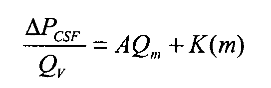
wobei:ΔPCSF der Unterschied der Druckwerte am Eingang und am Ausgang des Filtermediums (10) ist,ρ die Dichte der Auspuffgase ist,Qv der volumenbezogene Fluss der das Filtermedium durchströmenden Auspuffgase ist,Qm der massebezogene Fluss der das Filtermedium durchströmenden Auspuffgase ist, undA eine Konstante ist. - Verfahren nach einem der Ansprüche 1 bis 7, dadurch gekennzeichnet, dass das im Speicher (46) gespeicherte Verhältnis zwischen der Permeabilität K(m) des Filtermediums (10) und der in dem Filtermedium enthaltenen Partikellast in Form einer affinen Funktion vorhanden ist.
- Verfahren nach einem der Ansprüche 1 bis 8, dadurch gekennzeichnet, dass das im Speicher (46) gespeicherte Verhältnis zwischen der Permeabilität K(m) des Filtermediums (10) und der in dem Filtermedium enthaltenen Partikellast in folgender Form vorhanden ist:

wobei B eine empirische Konstante ist und C die Permeabilität des Filtermediums ohne Partikellast darstellt. - Verfahren nach einem der Ansprüche 1 bis 9, dadurch gekennzeichnet, dass es ferner eine Diagnose des Zustands des Filtermediums (10) umfasst, wobei diese Diagnose die folgenden Schritte umfasst:- Speichern des Permeabilitätswertes ohne Partikellast C des Filtermediums (10) im Speicher, wenn keine Partikellast vorhanden ist,- Vergleichen dieses Permeabilitätswertes ohne Partikellast C mit einem aus dem Wert des Unterschieds ΔPFiltermedium der Druckwerte (28, 30) am Eingang und am Ausgang des Filtermediums und mindestens einem Wert der Auspuffgasmenge berechneten Wert, und- in Abhängigkeit vom Größenunterschied zwischen dem Wert der Permeabilität ohne Partikellast C und dem berechneten Wert:- Diagnose einer anormalen Leckage von Auspuffgasen oder einer anormalen Permeabilität im Filtermedium, und/oder- Diagnose eines anormal hohen Widerstandes gegen die Gasmenge, beispielsweise auf Grund einer Verglasung oder eines Schmelzens des Filtermediums.
- Verfahren nach einem der Ansprüche 1 bis 10, dadurch gekennzeichnet, dass der berechnete Wert gleich ist:

wobei ΔPCSF der Druckunterschied stromaufwärts und stromabwärts zum Filtermedium (10) ist,
Qv der volumenbezogene Fluss des das Filtermedium durchströmenden Auspuffgases ist,
Qm der massebezogene Fluss des das Filtermedium durchströmenden Auspuffgases ist, und
A eine Konstante ist,
und dass diagnostiziert wird:- eine anormale Leckage der Auspuffgase oder eine anormale Permeabilität im Filtermedium, wenn der berechnete Wert geringer als die Permeabilität ohne Partikellast C ist, und/oder- ein anormal hoher Widerstand gegen die Gasmenge, beispielsweise auf Grund einer Verglasung oder eines Schmelzens des Filtermediums, wenn der berechnete Wert größer als die Permeabilität ohne Partikellast C ist, wobei eventuell eine Marge R berücksichtigt wird, um einen höheren Widerstand auf Grund einer normalen Partikelmenge im Filtermedium anzupassen. - Verfahren nach einem der Ansprüche 1 bis 11, dadurch gekennzeichnet, dass es einen Schritt der Steuerung der Regeneration des Filtermediums (10) umfasst, wenn die Bestimmung der Partikellast in diesem eine vorbestimmte Grenze überschreitet.
- Verfahren nach einem der Ansprüche 1 bis 12, dadurch gekennzeichnet, dass es in einer Kontroll- und Steuerschleife eingesetzt wird, die die folgenden Verfahrensschritte einsetzt:a - Aufzeichnung von ΔPCSF, Qm und Qv;b - Berechnung von
 c - Berechnung von
 d - wenn m(t) = vorbestimmte kritische Grenze mGrenze ist, Auslösung der Regeneratione - Wiederholung der Schritte a bis c bis m(t)=0f - wenn m(t)=0 Ende der Regenerationg - Kontrolle der Integrität des Filtermediums durch Überprüfung folgender Bedingung:wobei:
 ΔPCSF der Druckunterschied am Eingang und am Ausgang des Filtermediums (10) ist,B eine empirische Konstante ist,Qv der volumenbezogene Fluss des das Filtermedium durchströmenden Auspuffgases ist,Qm der massebezogene Fluss des das Filtermedium durchströmenden Auspuffgases ist,C die Permeabilität des Substrats in der Partikellast darstellt, undA eine Konstante ist.
 - Verfahren nach einem der Ansprüche 1 bis 13, dadurch gekennzeichnet, dass der Wert des Drucks der Auspuffgase am Eingang des Filtermediums (10), der verwendet wird, um den Unterschied ΔPFiltermedium der Druckwerte am Eingang und am Ausgang des Filtermediums zu bestimmen, mit Hilfe eines Druckfühlers (28) bestimmt wird.
- Verfahren nach einem der Ansprüche 1 bis 13, dadurch gekennzeichnet, dass der Wert des Drucks der Auspuffgase am Eingang des Filtermediums (10), der verwendet wird, um den Unterschied ΔPFiltermedium der Druckwerte am Eingang und am Ausgang des Filtermediums zu bestimmen, durch Berechnung aus Daten im Zusammenhang mit der Funktion des Motors (4) bestimmt wird.
- Verfahren zum Auslösen einer Regenerationsphase eines Filtermediums (10) eines Auspuffsystems (6) eines Verbrennungsmotors (4), dadurch gekennzeichnet, dass es die folgenden Schritte umfasst:- Bestimmung der in dem Filtermedium (10) vorhandenen Partikellast in definierten Zeitintervallen durch Einsatz des Verfahrens nach einem der Ansprüche 1 bis 14, und- wenn die bestimmte Partikellast eine bestimmte Grenze überschreitet, Auslösen der Regenerationsphase des Filtermediums.
- Verfahren nach Anspruch 16, dadurch gekennzeichnet, dass es ferner die folgenden Schritte umfasst:- in regelmäßigen Zeitintervallen Bestimmung während und/oder nach der Regenerationsphase der in dem Filtermedium (10) vorhandenen Partikellast durch Einsatz des Verfahrens nach einem der Ansprüche 1 bis 15,- Berechnen der regenerierten Partikellast unter Berücksichtigung des Unterschiedes der Partikellast zwischen zwei Intervallen der Bestimmung der regenerierten Partikellast, und- Steuerung der Dauer und/oder der Frequenz der Regenerationsphasen in Abhängigkeit von der im Filtermedium vorhandenen Partikellast und/oder der regenerierten Partikellast.
- Vorrichtung zur Bestimmung der in einem Filtermedium (10) eines Auspuffsystems (6) eines Verbrennungsmotors (4) vorhandenen Partikellast, dadurch gekennzeichnet, dass sie umfasst:- einen Speicher (46), der bei der Bestimmung der Partikellast zugänglich ist und ein Verhältnis zwischen der Permeabilität K(m) des Filtermediums (10) und der Partikellast speichert, insbesondere der Masse m, die in dem Filtermedium (10) enthalten ist,- Mittel (24, 26, 28, 30), um den Unterschied ΔPFiltermedium der Druckwerte (28, 30) am Eingang und am Ausgang des Filtermediums (10) zu berechnen, der der Summe der beiden Komponenten (ΔP1, ΔP2) gleichgesetzt wird, wobei die erste (ΔP1) den Lastverlust darstellt, der durch das Ausströmen der Gase am Eingang und am Ausgang des Filtermediums (10) erzeugt wird, und die zweite (ΔP2) den Lastverlust darstellt, der von den Auspuffgasen beim Durchströmen des Filtermediums (10) erzeugt wird, und die Permeabilität K(m) als Variable enthält,- Mittel (36) zur Bestimmung der Gasmenge (Qv), die durch das Filtermedium (10) strömt,- Mittel (36) zur Berechnung des Wertes der Permeabilität K(m) des Filtermediums (10) aus den bestimmten Werten, und- Mittel (36) zur Bestimmung des Wertes der Partikellast, die im Filtermedium (10) gespeichert ist, aus dem Wert der Permeabilität K(m) und dem im Speicher (46) gespeicherten Verhältnis.
- Vorrichtung nach Anspruch 18, dadurch gekennzeichnet, dass sie Speichermittel (36, 38, 46) umfasst, die einen ausführbaren Code enthalten, der dazu bestimmt ist, das Verfahren nach einem der Ansprüche 1 bis 18 einzusetzen.
- Motoreinheit, umfassend:- einen Verbrennungsmotor (4),- ein Auspuffsystem (6) für die Auspuffgase des Motors, umfassend ein Filtermedium (10),- ein intelligentes Mittel (18), das es ermöglicht, die Regeneration des Filtermediums nach bestimmten Kriterien zu steuern,dadurch gekennzeichnet, dass sie eine Vorrichtung zur Bestimmung der in einem Filtermedium (10) vorhandenen Partikellast nach einem der Ansprüche 18 oder 19 umfasst.
Applications Claiming Priority (2)
| Application Number | Priority Date | Filing Date | Title |
|---|---|---|---|
| FR0305578A FR2854650B1 (fr) | 2003-05-07 | 2003-05-07 | Procede et dispositif de determination de la quantite de particules presente dans un media filtrant d'un systeme d'echappement d'un moteur thermique et ensemble de motorisation le comprenant |
| FR0305578 | 2003-05-07 |
Publications (2)
| Publication Number | Publication Date |
|---|---|
| EP1475523A1 EP1475523A1 (de) | 2004-11-10 |
| EP1475523B1 true EP1475523B1 (de) | 2006-08-16 |
Family
ID=32982382
Family Applications (1)
| Application Number | Title | Priority Date | Filing Date |
|---|---|---|---|
| EP04300263A Expired - Lifetime EP1475523B1 (de) | 2003-05-07 | 2004-05-07 | Verfahren und Vorrichtung zur Bestimmung der Menge an vorhandenen Partikeln in einem Filtermittel im Abgasstrang eines Verbrennungsmotors |
Country Status (4)
| Country | Link |
|---|---|
| EP (1) | EP1475523B1 (de) |
| DE (1) | DE602004001913T2 (de) |
| ES (1) | ES2271814T3 (de) |
| FR (1) | FR2854650B1 (de) |
Families Citing this family (7)
| Publication number | Priority date | Publication date | Assignee | Title |
|---|---|---|---|---|
| DE502006004445D1 (de) * | 2006-05-09 | 2009-09-17 | Ford Global Tech Llc | Verfahren und Vorrichtung zur Abschätzung der Rußbeladung eines Dieselpartikelfilters |
| DE102008014509B4 (de) | 2008-03-15 | 2022-09-29 | Mercedes-Benz Group AG | Verfahren und Vorrichtung zum Ermitteln einer Masse an Ruß in einem Partikelfilter |
| WO2010062872A1 (en) * | 2008-11-26 | 2010-06-03 | Corning Incorporated | Systems and methods for estimating particulate load in a particulate filter |
| US8161738B2 (en) | 2008-11-26 | 2012-04-24 | Corning Incorporated | Systems and methods for estimating particulate load in a particulate filter |
| US8069658B2 (en) * | 2008-11-26 | 2011-12-06 | Corning Incorporated | Methods for estimating particulate load in a particulate filter, and related systems |
| FR3069017B1 (fr) * | 2017-07-12 | 2021-07-16 | Psa Automobiles Sa | Procede de confirmation d’un diagnostic de colmatage d’un filtre a particules |
| DE102019206682A1 (de) | 2019-05-09 | 2020-11-12 | Robert Bosch Gmbh | Verfahren zum Betrieb eines Partikelfilters in einem Abgasnachbehandlungssystem einer Brennkraftmaschine |
Family Cites Families (7)
| Publication number | Priority date | Publication date | Assignee | Title |
|---|---|---|---|---|
| JPS6047937A (ja) * | 1983-08-26 | 1985-03-15 | Mitsubishi Motors Corp | ディ−ゼルパティキュレ−ト捕集量測定装置 |
| FR2774421B1 (fr) * | 1998-02-02 | 2000-04-21 | Peugeot | Systeme de gestion du fonctionnement d'un filtre a particules associe a un moteur diesel notamment de vehicule automobile |
| US6377171B1 (en) * | 1999-09-15 | 2002-04-23 | Peerless Mfg. Co. | On-line filter monitoring system |
| FR2817286B1 (fr) * | 2000-11-24 | 2003-01-24 | Renault | Procede de regeneration d'un filtre a particules |
| FR2828236B1 (fr) * | 2001-08-01 | 2003-09-26 | Renault | Procede de determination du chargement d'un filtre a particules |
| DE10146316A1 (de) * | 2001-09-20 | 2003-04-10 | Bosch Gmbh Robert | Verfahren und Vorrichtung zur Steuerung eines Abgasnachbehandlungssystems |
| ITTO20020072A1 (it) * | 2002-01-25 | 2003-07-25 | Fiat Ricerche | Metodo per la determinazione della quantita' di particolato accumulata in un filtro per particolato. |
-
2003
- 2003-05-07 FR FR0305578A patent/FR2854650B1/fr not_active Expired - Lifetime
-
2004
- 2004-05-07 EP EP04300263A patent/EP1475523B1/de not_active Expired - Lifetime
- 2004-05-07 DE DE602004001913T patent/DE602004001913T2/de not_active Expired - Lifetime
- 2004-05-07 ES ES04300263T patent/ES2271814T3/es not_active Expired - Lifetime
Also Published As
| Publication number | Publication date |
|---|---|
| FR2854650A1 (fr) | 2004-11-12 |
| ES2271814T3 (es) | 2007-04-16 |
| DE602004001913T2 (de) | 2007-09-06 |
| EP1475523A1 (de) | 2004-11-10 |
| FR2854650B1 (fr) | 2007-12-21 |
| DE602004001913D1 (de) | 2006-09-28 |
Similar Documents
| Publication | Publication Date | Title |
|---|---|---|
| EP2283212A1 (de) | Verfahren und vorrichtung zur erkennung der verbrennung bei einem partikelfilter | |
| FR2781251A1 (fr) | Procede et dispositif de determination du chargement en suies d'un filtre a particules | |
| EP0661429B1 (de) | Verfahren und Vorrichtung zur einstellbaren Dosierung eines Zusatzmittels zur Regenerierung für Partikelfilter | |
| EP2695858B1 (de) | System zur Lagerung und Abgabe von gasförmigem Ammoniak | |
| EP1281843B1 (de) | Verfahren zur Bestimmung des Beladungszustandes eines Partikelfilters | |
| EP1514015B1 (de) | Verfahren zur regeneration eines kraftfahrzeugteilchenfilters und system zur steuerung der regeneration solch eines filters | |
| EP1475523B1 (de) | Verfahren und Vorrichtung zur Bestimmung der Menge an vorhandenen Partikeln in einem Filtermittel im Abgasstrang eines Verbrennungsmotors | |
| FR2976321A1 (fr) | Procede et dispositif de diagnostic d'un filtre a particules de moteur a combustion interne | |
| EP2182191B1 (de) | Verfahren zur Überwachung eines Partikelfilters | |
| EP2423477B1 (de) | Verfahren zur Feststellung des physikalischen Zustandes eines Partikelfilters | |
| FR2872212A1 (fr) | Systeme d'evaluation de l'etat de charge de moyens de depollution d'une ligne d'echappement | |
| FR2930290A3 (fr) | Procede de gestion de cycle de regeneration d'un systeme de moteur a combustion. | |
| EP1807618B1 (de) | Verfahren zur ausarbeitung einer temperaturinstruktions-kartographie beim eintritt in einem partikelfilter | |
| EP2532853B1 (de) | Steuerverfahren für die Regeneration eines Partikelfilters | |
| EP3679236A1 (de) | Verfahren zum schutz eines partikelfilters in einer abgasleitung während der regeneration | |
| EP1413720B1 (de) | Verfahren zum Ermitteln der Innentemperatur eines Partikelfilters, Verfahren zur Steuerung der Regeneration des Partikelfilters, sowie Steuerungssystem und Partikelfilter | |
| WO2007071862A1 (fr) | Procede et systeme de regeneration du filtre a particules d'un moteur thermique | |
| EP2173982B1 (de) | System und verfahren zur regeneration eines katalysatorpartikelfilters in einer dieselmotor-abgasleitung | |
| EP3237738B1 (de) | Verfahren zur regeneration einer stickoxidfalle | |
| FR2902467A1 (fr) | Systeme de regulation de la pression de suralimentation d'un moteur et procede de regulation | |
| FR2855213A1 (fr) | Procede et dispositif pour controler la regeneration d'un filtre a particules et ensemble de motorisation comprenant un tel dispositif | |
| WO2006056718A1 (fr) | Procede et dispositif d'arret d'une phase de regeneration de filtre a particules de moteur diesel de vehicule automobile | |
| FR2970040A1 (fr) | Dispositif de regeneration d'un filtre a particules equipant une ligne d'echappement d'un moteur thermique | |
| EP2312137A2 (de) | Diagnoseverfahren einer Anomalie in der Abgasleitung eines mit einem Partikelfilter ausgestatteten Verbrennungsmotors | |
| FR2879244A1 (fr) | Dispositif de commande de la regeneration d'un filtre a particules pour moteur a combustion interne et procede correspondant. |
Legal Events
| Date | Code | Title | Description |
|---|---|---|---|
| PUAI | Public reference made under article 153(3) epc to a published international application that has entered the european phase |
Free format text: ORIGINAL CODE: 0009012 |
|
| AK | Designated contracting states |
Kind code of ref document: A1 Designated state(s): AT BE BG CH CY CZ DE DK EE ES FI FR GB GR HU IE IT LI LU MC NL PL PT RO SE SI SK TR |
|
| AX | Request for extension of the european patent |
Extension state: AL HR LT LV MK |
|
| 17P | Request for examination filed |
Effective date: 20050510 |
|
| AKX | Designation fees paid |
Designated state(s): BE DE ES FR GB IT |
|
| GRAP | Despatch of communication of intention to grant a patent |
Free format text: ORIGINAL CODE: EPIDOSNIGR1 |
|
| GRAS | Grant fee paid |
Free format text: ORIGINAL CODE: EPIDOSNIGR3 |
|
| GRAA | (expected) grant |
Free format text: ORIGINAL CODE: 0009210 |
|
| AK | Designated contracting states |
Kind code of ref document: B1 Designated state(s): BE DE ES FR GB IT |
|
| PG25 | Lapsed in a contracting state [announced via postgrant information from national office to epo] |
Ref country code: IT Free format text: LAPSE BECAUSE OF FAILURE TO SUBMIT A TRANSLATION OF THE DESCRIPTION OR TO PAY THE FEE WITHIN THE PRESCRIBED TIME-LIMIT;WARNING: LAPSES OF ITALIAN PATENTS WITH EFFECTIVE DATE BEFORE 2007 MAY HAVE OCCURRED AT ANY TIME BEFORE 2007. THE CORRECT EFFECTIVE DATE MAY BE DIFFERENT FROM THE ONE RECORDED. Effective date: 20060816 |
|
| REG | Reference to a national code |
Ref country code: GB Ref legal event code: FG4D Free format text: NOT ENGLISH |
|
| REF | Corresponds to: |
Ref document number: 602004001913 Country of ref document: DE Date of ref document: 20060928 Kind code of ref document: P |
|
| GBT | Gb: translation of ep patent filed (gb section 77(6)(a)/1977) |
Effective date: 20061031 |
|
| REG | Reference to a national code |
Ref country code: ES Ref legal event code: FG2A Ref document number: 2271814 Country of ref document: ES Kind code of ref document: T3 |
|
| PLBE | No opposition filed within time limit |
Free format text: ORIGINAL CODE: 0009261 |
|
| STAA | Information on the status of an ep patent application or granted ep patent |
Free format text: STATUS: NO OPPOSITION FILED WITHIN TIME LIMIT |
|
| 26N | No opposition filed |
Effective date: 20070518 |
|
| REG | Reference to a national code |
Ref country code: FR Ref legal event code: ST Effective date: 20080131 |
|
| PG25 | Lapsed in a contracting state [announced via postgrant information from national office to epo] |
Ref country code: FR Free format text: LAPSE BECAUSE OF NON-PAYMENT OF DUE FEES Effective date: 20070531 |
|
| PGFP | Annual fee paid to national office [announced via postgrant information from national office to epo] |
Ref country code: DE Payment date: 20170523 Year of fee payment: 14 Ref country code: GB Payment date: 20170519 Year of fee payment: 14 |
|
| PGFP | Annual fee paid to national office [announced via postgrant information from national office to epo] |
Ref country code: ES Payment date: 20170628 Year of fee payment: 14 Ref country code: BE Payment date: 20170519 Year of fee payment: 14 |
|
| REG | Reference to a national code |
Ref country code: DE Ref legal event code: R119 Ref document number: 602004001913 Country of ref document: DE |
|
| GBPC | Gb: european patent ceased through non-payment of renewal fee |
Effective date: 20180507 |
|
| REG | Reference to a national code |
Ref country code: BE Ref legal event code: MM Effective date: 20180531 |
|
| PG25 | Lapsed in a contracting state [announced via postgrant information from national office to epo] |
Ref country code: GB Free format text: LAPSE BECAUSE OF NON-PAYMENT OF DUE FEES Effective date: 20180507 Ref country code: DE Free format text: LAPSE BECAUSE OF NON-PAYMENT OF DUE FEES Effective date: 20181201 |
|
| PG25 | Lapsed in a contracting state [announced via postgrant information from national office to epo] |
Ref country code: BE Free format text: LAPSE BECAUSE OF NON-PAYMENT OF DUE FEES Effective date: 20180531 |
|
| REG | Reference to a national code |
Ref country code: ES Ref legal event code: FD2A Effective date: 20190913 |
|
| PG25 | Lapsed in a contracting state [announced via postgrant information from national office to epo] |
Ref country code: ES Free format text: LAPSE BECAUSE OF NON-PAYMENT OF DUE FEES Effective date: 20180508 |