EP1475596A2 - Plate heat exchanger with single and dopple wall plates - Google Patents
Plate heat exchanger with single and dopple wall plates Download PDFInfo
- Publication number
- EP1475596A2 EP1475596A2 EP04009741A EP04009741A EP1475596A2 EP 1475596 A2 EP1475596 A2 EP 1475596A2 EP 04009741 A EP04009741 A EP 04009741A EP 04009741 A EP04009741 A EP 04009741A EP 1475596 A2 EP1475596 A2 EP 1475596A2
- Authority
- EP
- European Patent Office
- Prior art keywords
- heat exchanger
- walled
- plate
- exchanger plates
- heat
- Prior art date
- Legal status (The legal status is an assumption and is not a legal conclusion. Google has not performed a legal analysis and makes no representation as to the accuracy of the status listed.)
- Granted
Links
Images




Classifications
-
- F—MECHANICAL ENGINEERING; LIGHTING; HEATING; WEAPONS; BLASTING
- F28—HEAT EXCHANGE IN GENERAL
- F28F—DETAILS OF HEAT-EXCHANGE AND HEAT-TRANSFER APPARATUS, OF GENERAL APPLICATION
- F28F3/00—Plate-like or laminated elements; Assemblies of plate-like or laminated elements
- F28F3/02—Elements or assemblies thereof with means for increasing heat-transfer area, e.g. with fins, with recesses, with corrugations
- F28F3/04—Elements or assemblies thereof with means for increasing heat-transfer area, e.g. with fins, with recesses, with corrugations the means being integral with the element
- F28F3/042—Elements or assemblies thereof with means for increasing heat-transfer area, e.g. with fins, with recesses, with corrugations the means being integral with the element in the form of local deformations of the element
- F28F3/046—Elements or assemblies thereof with means for increasing heat-transfer area, e.g. with fins, with recesses, with corrugations the means being integral with the element in the form of local deformations of the element the deformations being linear, e.g. corrugations
-
- F—MECHANICAL ENGINEERING; LIGHTING; HEATING; WEAPONS; BLASTING
- F28—HEAT EXCHANGE IN GENERAL
- F28D—HEAT-EXCHANGE APPARATUS, NOT PROVIDED FOR IN ANOTHER SUBCLASS, IN WHICH THE HEAT-EXCHANGE MEDIA DO NOT COME INTO DIRECT CONTACT
- F28D9/00—Heat-exchange apparatus having stationary plate-like or laminated conduit assemblies for both heat-exchange media, the media being in contact with different sides of a conduit wall
- F28D9/0031—Heat-exchange apparatus having stationary plate-like or laminated conduit assemblies for both heat-exchange media, the media being in contact with different sides of a conduit wall the conduits for one heat-exchange medium being formed by paired plates touching each other
- F28D9/0043—Heat-exchange apparatus having stationary plate-like or laminated conduit assemblies for both heat-exchange media, the media being in contact with different sides of a conduit wall the conduits for one heat-exchange medium being formed by paired plates touching each other the plates having openings therein for circulation of at least one heat-exchange medium from one conduit to another
- F28D9/005—Heat-exchange apparatus having stationary plate-like or laminated conduit assemblies for both heat-exchange media, the media being in contact with different sides of a conduit wall the conduits for one heat-exchange medium being formed by paired plates touching each other the plates having openings therein for circulation of at least one heat-exchange medium from one conduit to another the plates having openings therein for both heat-exchange media
Definitions
- the invention is in the field of plate heat exchangers.
- Plate heat exchangers are used to transfer thermal energy between heat exchange fluids transferred to. At least two heat exchanger fluids flow through separate fluids Flow spaces formed between heat exchanger plates in the plate heat exchanger are.
- the heat exchanger plates are usually arranged in a stack, which Is part of the plate heat exchanger.
- the separate flow spaces are created using of openings formed in the heat exchanger plates and between the heat exchanger plates trained spaces.
- a heat transfer between the at least two heat exchanger fluids essentially take place in the region of one central heat transfer section of the heat exchanger plates instead.
- To transfer the Thermal energy flows through one of the heat exchanger fluids through a flow space on one Side of a heat exchanger plate and another heat exchanger fluid through a flow space on the other side of the heat exchanger plate. Through the heat exchanger plate heat is then passed between the two heat exchanger fluids flowing in countercurrent replaced.
- plate heat exchangers in which the stacked heat exchanger plates each are designed as single-walled heat exchanger plates with a single plate element, plate heat exchangers are known, in which all relevant for heat transfer Heat exchanger plates of the stack are designed as double-walled heat exchanger plates are. Double-walled heat exchanger plates are made using two plate elements formed that closely at least in the area of the central heat transfer section come to rest against each other.
- plate heat exchangers with a stack of double-walled heat exchanger plates can be used for applications where three separate flow spaces for three heat exchanger fluids with the help of the openings in the heat exchanger plates and the gaps between the heat exchanger plates in a plate heat exchanger are formed.
- the object of the invention is to provide an improved plate heat exchanger with which the application possibilities for the use of plate heat exchangers are expanded.
- the invention encompasses the idea of a plate heat exchanger with a stack of Heat exchanger plates that are permanently connected to each other and separated between them Flow spaces for at least two heat exchanger fluids are to be provided, in which a part of the heat exchanger plates usable for heat transfer each as a single-walled heat exchanger plate with one plate element and another Part of the heat exchanger plates usable for heat transfer each as a double wall Heat exchanger plate is designed with two plate elements.
- plate heat exchangers can be manufactured, which as a single component sections in Have stacks of heat exchanger plates that meet various safety standards.
- a plate heat exchanger enables plate heat exchangers for applications manufacture, in which to some extent the use of the more expensive double-walled Heat exchanger plates for the purpose of ensuring an adequate safety standard is necessary, but also at least a part of the heat exchanger plates can also be single-walled, because for some of the in the plate heat exchanger formed flow spaces a lower safety standard is sufficient.
- Such use cases are particularly present when flow spaces in the plate heat exchanger are formed for more than two heat exchanger fluids. In this case it happens often before that regarding the heat transfer between one of the heat exchanger fluids and another of the heat exchanger fluids to ensure a higher safety standard is what the double-walled design of the heat exchanger plates requires. In terms of the heat transfer between the one heat exchanger fluid and another of the Heat exchanger fluids, however, a low safety standard is sufficient, so that the heat exchanger plates can be single-walled here.
- the combination of double-walled and single-walled heat exchanger plates has this furthermore the advantage that in this way in a plate heat exchanger, which is usually is designed with double-walled heat exchanger plates, in some cases more efficient heat transfer used in connection with the single-walled heat exchanger plates can be.
- using the combination of the two types of heat exchanger plates the manufacturing cost compared to the known, exclusively plate heat exchangers equipped with double-walled heat exchanger plates.
- Figure 1 shows a schematic representation of an arrangement with several single-walled Heat exchanger plates 1 and several double-walled heat exchanger plates 2. Both Types of heat exchanger plates each have a central heat transfer section 3 and openings 4 in corner areas 5. In the area outside the openings 4 Embossments 6 are provided for forming surface structures. The embossing 6 support the spaced arrangement of the single-walled / double-walled heat exchanger plates 1, 2 for forming the flow spaces when using the single-walled / double-walled Heat exchanger plates 1, 2 in a plate heat exchanger.
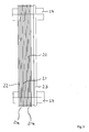
- a plate heat exchanger 20 is shown in front and side view.
- the plate heat exchanger comprises a stack 21 with the arrangement of the single-walled / double-walled Heat exchanger plates 1, 2 according to Figure 1, the single-walled / double-walled Heat exchanger plates 1, 2 permanently connected to each other by means of soldering are.
- the plate heat exchanger 20 further comprises two outer plates 22, 23 with Connections 24 for introducing and discharging the heat exchanger fluids. Between the several Heat exchanger plates 1, 2 are separate flow spaces for the connections 24 introduced / removed heat exchanger fluids formed.
- the heat exchanger fluids are along the heat exchanger plates 1, 2 through the separate flow spaces in Countercurrent led.
- the embossments 6 cause in the central heat transfer sections 3 of the single-walled / double-walled heat exchanger plates 1, 2 a highly turbulent Flow of the heat exchanger fluids between the several heat exchanger plates 1, 2.
- FIG. 4 shows a cross-sectional illustration of the plate heat exchanger 20 according to FIG. 2 a line AA 'in Figure 2.
- the stack 21 in the illustrated embodiment of the plate heat exchanger 20 comprises three double-walled heat exchanger plates 2a, 2b, 2c, each have two plate elements 2a ', 2a ", 2b', 2b" and 2c ', 2c ".
- Both the single-walled as the double-walled heat exchanger plates 1, 2 have one opposite the plane of the central heat transfer section 3 raised edge 26.
- an optional outer edge 27 is formed, which is bent outwards so that the outer edge 27 substantially parallel to the plane of the central heat transfer section 3 runs. In an alternative embodiment, can the outer edge 27 may be omitted.
- heat exchanger fluid is what is due to a leak in one of the two plate elements 2a ', 2a “, 2b', 2b” or 2c ', 2c "between the plate elements 2a', 2a", 2b ', 2b “ or 2c ', 2c "and reaches the region of the edge 26 due to capillary action, already visible from the outside in an area 28.
- the single-walled and double-walled heat exchanger plates 1, 2 each in separate stacks 21a, 21b summarized.
- Heat exchanger plates 1, 2 can be provided, for example with several stacks of single-walled / double-walled heat exchanger plates 1, 2 in a plate heat exchanger.
Landscapes
- Engineering & Computer Science (AREA)
- Physics & Mathematics (AREA)
- Thermal Sciences (AREA)
- Mechanical Engineering (AREA)
- General Engineering & Computer Science (AREA)
- Heat-Exchange Devices With Radiators And Conduit Assemblies (AREA)
- Separation By Low-Temperature Treatments (AREA)
Abstract
Description
Die Erfindung liegt auf dem Gebiet von Plattenwärmeübertragern.The invention is in the field of plate heat exchangers.
Plattenwärmeübertrager werden genutzt, um Wärmeenergie zwischen Wärmetauscher-Fluiden zu übertragen. Hierbei durchströmen wenigstens zwei Wärmetauscher-Fluide getrennte Durchflußräume, die zwischen Wärmeübertragerplatten in dem Plattenwärmeübertrager gebildet sind. Die Wärmeübertragerplatten sind üblicherweise in einem Stapel angeordnet, welcher Teil des Plattenwärmeübertragers ist. Die getrennten Durchflußräume werden mit Hilfe von in den Wärmeübertragerplatten gebildeten Durchbrüchen und zwischen den Wärmeübertragerplatten ausgebildeten Zwischenräumen geschaffen. Eine Wärmeübertragung zwischen den wenigstens zwei Wärmetauscher-Fluiden findet hierbei im wesentlichen im Bereich eines zentralen Wärmeübergangsabschnitts der Wärmeübertragerplatten statt. Zur Übertragung der Wärmeenergie strömt eines der Wärmetauscher-Fluide durch einen Durchflußraum auf einer Seite einer Wärmeübertragerplatte und ein anderes Wärmetauscher-Fluid durch einen Durchflußraum auf der anderen Seite der Wärmeübertragerplatte. Durch die Wärmeübertragerplatte hindurch wird dann Wärme zwischen den beiden im Gegenstrom fließenden Wärmetauscher-Fluiden ausgetauscht.Plate heat exchangers are used to transfer thermal energy between heat exchange fluids transferred to. At least two heat exchanger fluids flow through separate fluids Flow spaces formed between heat exchanger plates in the plate heat exchanger are. The heat exchanger plates are usually arranged in a stack, which Is part of the plate heat exchanger. The separate flow spaces are created using of openings formed in the heat exchanger plates and between the heat exchanger plates trained spaces. A heat transfer between the at least two heat exchanger fluids essentially take place in the region of one central heat transfer section of the heat exchanger plates instead. To transfer the Thermal energy flows through one of the heat exchanger fluids through a flow space on one Side of a heat exchanger plate and another heat exchanger fluid through a flow space on the other side of the heat exchanger plate. Through the heat exchanger plate heat is then passed between the two heat exchanger fluids flowing in countercurrent replaced.
Neben Plattenwärmeübertragern, bei denen die gestapelten Wärmeübertragerplatten jeweils als einwandige Wärmeübertragerplatten mit einem einzelnen Plattenelement ausgebildet sind, sind Plattenwärmeübertrager bekannt, bei denen sämtliche für die Wärmeübertragung relevanten Wärmeübertragerplatten des Stapels als doppelwandige Wärmeübertragerplatten ausgeführt sind. Doppelwandige Wärmeübertragerplatten werden mit Hilfe von zwei Plattenelementen gebildet, die mindestens im Bereich des zentralen Wärmeübergangsabschnitts eng aneinander zur Anlage kommen. Mit Hilfe doppelwandiger Wärmeübertragerplatten kann ein im Vergleich zu einwandigen Wärmeübertragerplatten höherer Sicherheitsstandard gewährleistet werden, indem bei einem Leck in einer der beiden Plattenelemente der doppelwandigen Wärmeübertragerplatte die beiden Wärmetauscher-Fluide nicht vermischt werden, da die Leckflüssigkeit lediglich in den Zwischenraum zwischen den beiden Plattenelementen und dort in den Randbereich nach außen gelangt, aber nicht auf die andere Seite der Wärmeübertragerplatte. Insbesondere Plattenwärmeübertrager mit einem Stapel doppelwandiger Wärmeübertragerplatten können für Anwendungen genutzt werden, bei denen drei getrennte Durchflußräume für drei Wärmetauscher-Fluide mit Hilfe der Durchbrüche in den Wärmeübertragerplatten und den Zwischenräumen zwischen den Wärmeübertragerplatten in einem Plattenwärmeübertrager gebildet sind.In addition to plate heat exchangers, in which the stacked heat exchanger plates each are designed as single-walled heat exchanger plates with a single plate element, plate heat exchangers are known, in which all relevant for heat transfer Heat exchanger plates of the stack are designed as double-walled heat exchanger plates are. Double-walled heat exchanger plates are made using two plate elements formed that closely at least in the area of the central heat transfer section come to rest against each other. With the help of double-walled heat exchanger plates, a guaranteed higher safety standard compared to single-walled heat exchanger plates by double-walled if there is a leak in one of the two plate elements Heat exchanger plate the two heat exchanger fluids cannot be mixed as the Leakage liquid only in the space between the two plate elements and there in the edge area to the outside, but not on the other side of the heat exchanger plate. In particular, plate heat exchangers with a stack of double-walled heat exchanger plates can be used for applications where three separate flow spaces for three heat exchanger fluids with the help of the openings in the heat exchanger plates and the gaps between the heat exchanger plates in a plate heat exchanger are formed.
Aufgabe der Erfindung ist es, einen verbesserten Plattenwärmeübertrager anzugeben, mit dem die Anwendungsmöglichkeiten zur Nutzung von Plattenwärmeübertragern erweitert werden.The object of the invention is to provide an improved plate heat exchanger with which the application possibilities for the use of plate heat exchangers are expanded.
Diese Aufgabe wird erfindungsgemäß durch einen Plattenwärmeübertrager nach dem unabhängigen Anspruch 1 gelöst.This object is achieved by a plate heat exchanger according to the independent Claim 1 solved.
Die Erfindung umfaßt den Gedanken, einen Plattenwärmeübertrager mit einem Stapel von Wärmeübertragerplatten, die dauerhaft miteinander verbunden sind und zwischen denen getrennte Durchflußräume für wenigstens zwei Wärmetauscher-Fluide gebildet sind, vorzusehen, bei dem ein Teil der für die Wärmeübertragung nutzbaren Wärmeübertragerplatten jeweils als eine einwandige Wärmeübertragerplatte mit einem Plattenelement und ein anderer Teil der für die Wärmeübertragung nutzbaren Wärmeübertragerplatten jeweils als eine doppelwandige Wärmeübertragerplatte mit zwei Plattenelementen ausgeführt ist. Auf diese Weise können Plattenwärmeübertrager hergestellt werden, die als einzelnes Bauteil Abschnitte im Stapel der Wärmeübertragerplatten aufweisen, die verschiedene Sicherheitsstandards erfüllen. Mit Hilfe der Kombination von einwandigen und doppelwandigen Wärmeübertragerplatten in einen Plattenwärmeübertrager wird es ermöglicht, Plattenwärmeübertrager für Anwendungen herzustellen, in denen zwar in gewissem Umfang die Nutzung der teureren doppelwandigen Wärmeübertragerplatten zu Zwecken der Gewährleistung eines ausreichenden Sicherheitsstandards notwendig ist, darüber hinaus aber wenigstens ein Teil der Wärmeübertragerplatten auch einwandig ausgeführt werden kann, da für einen Teil der in dem Plattenwärmeübertrager gebildeten Durchflußräume ein geringerer Sicherheitsstandard ausreichend ist. Derartige Anwendungsfälle liegen insbesondere dann vor, wenn in dem Plattenwärmeübertrager Durchflußräume für mehr als zwei Wärmetauscher-Fluide gebildet sind. In diesem Fall kommt es häufig vor, daß bezüglich des Wärmeübergangs zwischen einem der Wärmetauscher-Fluide und einem anderen der Wärmetauscher-Fluide ein höherer Sicherheitsstandard zu gewährleisten ist, was die doppelwandige Ausbildung der Wärmeübertragerplatten voraussetzt. Bezüglich des Wärmeübergangs zwischen dem einen Wärmetauscher-Fluid und einem weiteren der Wärmetauscher-Fluide reicht jedoch ein niedriger Sicherheitsstandard aus, so daß die Wärmeübertragerplatten hier einwandig ausgebildet werden können.The invention encompasses the idea of a plate heat exchanger with a stack of Heat exchanger plates that are permanently connected to each other and separated between them Flow spaces for at least two heat exchanger fluids are to be provided, in which a part of the heat exchanger plates usable for heat transfer each as a single-walled heat exchanger plate with one plate element and another Part of the heat exchanger plates usable for heat transfer each as a double wall Heat exchanger plate is designed with two plate elements. In this way plate heat exchangers can be manufactured, which as a single component sections in Have stacks of heat exchanger plates that meet various safety standards. With the help of the combination of single-walled and double-walled heat exchanger plates in A plate heat exchanger enables plate heat exchangers for applications manufacture, in which to some extent the use of the more expensive double-walled Heat exchanger plates for the purpose of ensuring an adequate safety standard is necessary, but also at least a part of the heat exchanger plates can also be single-walled, because for some of the in the plate heat exchanger formed flow spaces a lower safety standard is sufficient. Such use cases are particularly present when flow spaces in the plate heat exchanger are formed for more than two heat exchanger fluids. In this case it happens often before that regarding the heat transfer between one of the heat exchanger fluids and another of the heat exchanger fluids to ensure a higher safety standard is what the double-walled design of the heat exchanger plates requires. In terms of the heat transfer between the one heat exchanger fluid and another of the Heat exchanger fluids, however, a low safety standard is sufficient, so that the heat exchanger plates can be single-walled here.
Die Kombination von doppelwandigen und einwandigen Wärmeübertragerplatten hat darüber hinaus den Vorteil, daß auf diese Weise in einem Plattenwärmeübertrager, der üblicherweise mit doppelwandigen Wärmeübertragerplatten ausgeführt ist, zum Teil die effizientere Wärmeübertragung im Zusammenhang mit den einwandigen Wärmeübertragerplatten genutzt werden kann. Darüber hinaus werden mit Hilfe der Kombination der beiden Arten von Wärmeübertragerplatten die Herstellungskosten im Vergleich zu den bekannten, ausschließlich mit doppelwandigen Wärmeübertragerplatten ausgestatteten Plattenwärmeübertragern gesenkt.The combination of double-walled and single-walled heat exchanger plates has this furthermore the advantage that in this way in a plate heat exchanger, which is usually is designed with double-walled heat exchanger plates, in some cases more efficient heat transfer used in connection with the single-walled heat exchanger plates can be. In addition, using the combination of the two types of heat exchanger plates the manufacturing cost compared to the known, exclusively plate heat exchangers equipped with double-walled heat exchanger plates.
Die Vorteile der kombinierten Nutzung von einwandigen und doppelwandigen Wärmeübertragerplatten in einem Plattenwärmeübertrager werden insbesondere dann wirksam genutzt, wenn zwischen den Wärmeübertragerplatten getrennte Durchflußräume für drei Wärmetauscher-Fluide gebildet sind.The advantages of the combined use of single-walled and double-walled heat exchanger plates in a plate heat exchanger are used particularly effectively, if there are separate flow spaces for three heat exchanger fluids between the heat exchanger plates are formed.
Die Erfindung wird im folgenden anhand von Ausführungsbeispielen unter Bezugnahme auf eine Zeichnung näher erläutert. Hierbei zeigen:
- Figur 1
- einen Stapel mit mehreren Wärmeübertragerplatten;
Figur 2- eine schematische Darstellung eines Plattenwärmeübertragers in Vorderansicht;
Figur 3- eine schematische Darstellung des Plattenwärmeübertragers nach
Figur 2 in Seitenansicht; Figur 4- eine Querschnittsdarstellung des Plattenwärmeübertragers nach
Figur 2 entlang einer Linie AA' inFigur 2; und Figur 5- eine vergrößerte Darstellung eines Randbereichs der Querschnittsdarstellung in
Figur 4.
- Figure 1
- a stack with several heat exchanger plates;
- Figure 2
- a schematic representation of a plate heat exchanger in front view;
- Figure 3
- a schematic representation of the plate heat exchanger according to Figure 2 in side view;
- Figure 4
- a cross-sectional view of the plate heat exchanger according to Figure 2 along a line AA 'in Figure 2; and
- Figure 5
- 3 shows an enlarged representation of an edge region of the cross-sectional representation in FIG. 4.
Figur 1 zeigt eine schematische Darstellung einer Anordnung mit mehreren einwandigen
Wärmeübertragerplatten 1 und mehreren doppelwandigen Wärmeübertragerplatten 2. Beide
Arten von Wärmeübertragerplatten verfügen jeweils über einen zentralen Wärmeübergangsabschnitt
3 sowie Durchbrüche 4 in Eckbereichen 5. Im Bereich außerhalb der Durchbrüche 4
sind zum Ausbilden von Oberflächenstrukturen Prägungen 6 vorgesehen. Die Prägungen 6
unterstützen die beabstandete Anordnung der einwandigen/doppelwandigen Wärmeübertragerplatten
1, 2 zum Ausbilden der Durchflußräume bei der Nutzung der einwandigen/doppelwandigen
Wärmeübertragerplatten 1, 2 in einem Plattenwärmeübertrager.Figure 1 shows a schematic representation of an arrangement with several single-walled
Heat exchanger plates 1 and several double-walled
In den Figuren 2 und 3 ist ein Plattenwärmeübertrager 20 in Vorder- bzw. Seitenansicht gezeigt.
Der Plattenwärmeübertrager umfaßt einen Stapel 21 mit der Anordnung der einwandigen/doppelwandigen
Wärmeübertragerplatten 1, 2 nach Figur 1, wobei die einwandigen/doppelwandigen
Wärmeübertragerplatten 1, 2 mittels Lötens dauerhaft miteinander verbunden
sind. Der Plattenwärmeübertrager 20 umfaßt weiterhin zwei äußere Platten 22, 23 mit
Anschlüssen 24 zum Einführen und Abführen der Wärmetauscher-Fluide. Zwischen den mehreren
Wärmeübertragerplatten 1, 2 sind getrennte Durchflußräume für die über die Anschlüsse
24 eingeführten/abgeführten Wärmetauscher-Fluide gebildet. Die Wärmetauscher-Fluide
werden entlang der Wärmeübertragerplatten 1, 2 durch die getrennten Durchflußräume im
Gegenstrom geführt. Hierbei verursachen die Prägungen 6 in den zentralen Wärmeübergangsabschnitten
3 der einwandigen/doppelwandigen Wärmeübertragerplatten 1, 2 einen hochturbulenten
Durchfluß der Wärmetauscher-Fluide zwischen den mehreren Wärmeübertragerplatten
1, 2.In Figures 2 and 3, a
Figur 4 zeigt eine Querschnittsdarstellung des Plattenwärmeübertragers 20 nach Figur 2 entlang
einer Linie AA' in Figur 2. Zwischen den äußeren Platten 22, 23 ist der Stapel 21 mit
den einwandigen und den doppelwandigen Wärmeübertragerplatten 1, 2 angeordnet. Figur 5
zeigt eine vergrößerte Darstellung eines Randbereichs 25 der Querschnittsdarstellung in Figur
4. Hieraus ergibt sich, daß der Stapel 21 bei der dargestellten Ausrührungsform des Plattenwärmeübertragers
20 drei doppelwandige Wärmeübertragerplatten 2a, 2b, 2c umfaßt, die jeweils
zwei Plattenelemente 2a', 2a", 2b', 2b" bzw. 2c', 2c" aufweisen. Sowohl die einwandigen
als die doppelwandigen Wärmeübertragerplatten 1, 2 weisen einen gegenüber der Ebene
des zentralen Wärmeübergangsabschnitts 3 hochgestellten Rand 26 auf. An dem Rand 26
ist bei der dargestellten Ausführungsform ein optionaler äußerer Rand 27 angeformt, welcher
nach außen gebogen ist, so daß der äußere Rand 27 im wesentlichen parallel zur Ebene des
zentralen Wärmeübergangsabschnitts 3 verläuft. Bei einer alternativen Ausführungsform kann
der äußere Rand 27 weggelassen werden.FIG. 4 shows a cross-sectional illustration of the
Gemäß der Darstellung in Figur 5 sind die äußeren Ränder 27 der beiden Plattenelemente 2a',
2a", 2b', 2b" bzw. 2c', 2c" der doppelwandigen Wärmeübertragerplatten 2a, 2b, 2c voneinander
beabstandet, wohingegen die äußeren Ränder 27 der benachbarten doppelwandigen
Wärmeübertragerplatten 2a und 2b sowie 2b und 2c eng aneinander zur Anlage kommen. Auf
diese Weise wird Wärmetauscher-Fluid, was aufgrund eines Lecks in einer der zwei Plattenelemente
2a', 2a", 2b', 2b" bzw. 2c', 2c"zwischen die Plattenelemente 2a', 2a", 2b', 2b"
bzw. 2c', 2c" gelangt und aufgrund von Kapillarwirkung in den Bereich des Rands 26 gelangt,
bereits in einem Bereich 28 von außen sichtbar.As shown in FIG. 5, the
Bei der beschriebenen Ausführungsform des Plattenwärmeübertragers 20 sind die einwandigen
und doppelwandigen Wärmeübertragerplatten 1, 2 jeweils in separaten Stapeln 21a, 21b
zusammengefaßt. Es können jedoch beliebige Kombinationen von einwandigen und doppelwandigen
Wärmeübertragerplatten 1, 2 vorgesehen sein, beispielsweise mit mehreren Stapeln
von einwandigen/doppelwandigen Wärmeübertragerplatten 1, 2 in einem Plattenwärmeübertrager.In the described embodiment of the
Die in der vorstehenden Beschreibung, den Ansprüchen und der Zeichnung offenbarten Merkmale der Erfindung können sowohl einzeln als auch in beliebiger Kombination für die Verwirklichung der Erfindung in ihren verschiedenen Ausführungsformen von Bedeutung sein.Those disclosed in the foregoing description, claims and drawings Features of the invention can be used both individually and in any combination Realization of the invention in its various embodiments of importance his.
Claims (2)
Applications Claiming Priority (2)
| Application Number | Priority Date | Filing Date | Title |
|---|---|---|---|
| DE10320812A DE10320812B4 (en) | 2003-05-08 | 2003-05-08 | Plate heat exchangers with single-walled and double-walled heat exchanger plates |
| DE10320812 | 2003-05-08 |
Publications (3)
| Publication Number | Publication Date |
|---|---|
| EP1475596A2 true EP1475596A2 (en) | 2004-11-10 |
| EP1475596A3 EP1475596A3 (en) | 2005-10-19 |
| EP1475596B1 EP1475596B1 (en) | 2010-09-01 |
Family
ID=32981301
Family Applications (1)
| Application Number | Title | Priority Date | Filing Date |
|---|---|---|---|
| EP04009741A Expired - Lifetime EP1475596B1 (en) | 2003-05-08 | 2004-04-23 | Plate heat exchanger with single and dopple wall plates |
Country Status (7)
| Country | Link |
|---|---|
| US (1) | US6973961B2 (en) |
| EP (1) | EP1475596B1 (en) |
| CN (2) | CN100443848C (en) |
| AT (1) | ATE479874T1 (en) |
| CA (1) | CA2465441C (en) |
| DE (2) | DE10320812B4 (en) |
| NZ (1) | NZ532496A (en) |
Cited By (4)
| Publication number | Priority date | Publication date | Assignee | Title |
|---|---|---|---|---|
| WO2014140131A1 (en) * | 2013-03-12 | 2014-09-18 | Behr Gmbh & Co. Kg | Heat exchanger |
| EP2700894A4 (en) * | 2011-04-18 | 2014-12-31 | Mitsubishi Electric Corp | HEAT EXCHANGER OF THE PLATE TYPE, AND HEAT PUMP DEVICE |
| EP2741041A4 (en) * | 2011-07-13 | 2015-05-27 | Mitsubishi Electric Corp | PLATE HEAT EXCHANGER AND HEAT PUMP DEVICE |
| EP3404350A4 (en) * | 2016-01-13 | 2019-09-18 | Hisaka Works, Ltd. | HEAT EXCHANGER WITH PLATES |
Families Citing this family (14)
| Publication number | Priority date | Publication date | Assignee | Title |
|---|---|---|---|---|
| DE10317263B4 (en) * | 2003-04-14 | 2019-05-29 | Gea Wtt Gmbh | Plate heat exchanger with double-walled heat exchanger plates |
| SE532524C2 (en) * | 2008-06-13 | 2010-02-16 | Alfa Laval Corp Ab | Heat exchanger plate and heat exchanger assembly include four plates |
| USD679788S1 (en) * | 2008-10-07 | 2013-04-09 | Swep International Ab | Heat exchanger |
| FI20095267A7 (en) * | 2009-03-13 | 2010-09-14 | Mauri Kontu | Plate heat exchanger and method for improving the pressure resistance of a plate heat exchanger |
| US9163882B2 (en) | 2011-04-25 | 2015-10-20 | Itt Manufacturing Enterprises, Inc. | Plate heat exchanger with channels for ‘leaking fluid’ |
| WO2015082350A1 (en) * | 2013-12-05 | 2015-06-11 | Swep International Ab | Heat exchanger having improved strength |
| CN105742759B (en) * | 2016-04-22 | 2019-03-05 | 重庆超力高科技股份有限公司 | Battery coolant liquid temperature control device |
| CN107917629B (en) * | 2016-10-11 | 2020-12-18 | 恒丰工程(香港)有限公司 | Double-wall plate and shell heat exchanger and its special double-wall heat exchange plate |
| CA3037066A1 (en) | 2016-10-14 | 2018-04-19 | Dana Canada Corporation | Heat exchanger having aerodynamic features to improve performance |
| US11719495B2 (en) | 2018-03-15 | 2023-08-08 | Mitsubishi Electric Corporation | Plate heat exchanger, heat pump device including plate heat exchanger, and heat pump type of cooling, heating, and hot water supply system including heat pump device |
| JP6594598B1 (en) * | 2018-03-15 | 2019-10-23 | 三菱電機株式会社 | Plate type heat exchanger, heat pump device provided with plate type heat exchanger, and heat pump type heating hot water supply system provided with heat pump device |
| JP7062131B2 (en) * | 2019-03-18 | 2022-05-02 | 三菱電機株式会社 | Plate heat exchanger and heat pump device equipped with it |
| WO2022010313A1 (en) * | 2020-07-10 | 2022-01-13 | 한온시스템 주식회사 | Heat exchanger |
| EP4464971A1 (en) * | 2023-05-16 | 2024-11-20 | Danfoss A/S | Heat exchanger |
Family Cites Families (20)
| Publication number | Priority date | Publication date | Assignee | Title |
|---|---|---|---|---|
| US3537513A (en) * | 1968-03-11 | 1970-11-03 | Garrett Corp | Three-fluid heat exchanger |
| DE2518683C3 (en) * | 1975-04-26 | 1981-04-09 | 4P Verpackungen Gmbh, 8960 Kempten | Heat exchanger made from two aluminum sheets connected to one another |
| US4249597A (en) * | 1979-05-07 | 1981-02-10 | General Motors Corporation | Plate type heat exchanger |
| JPS5974496A (en) * | 1982-10-21 | 1984-04-26 | Matsushita Electric Ind Co Ltd | Plate-type heat exchanger |
| US4678027A (en) * | 1984-12-14 | 1987-07-07 | Paul Mueller Company | Dual-walled coiled plate heat exchanger with vented interface |
| EP0327574B1 (en) * | 1986-10-22 | 1994-04-13 | Alfa-Laval Thermal Ab | Plate heat exchanger with a double-wall structure |
| DE3903084A1 (en) * | 1989-02-02 | 1990-08-09 | Bergfeld & Heider Gmbh & Co Kg | Plate heat exchanger |
| SE9000712L (en) * | 1990-02-28 | 1991-08-29 | Alfa Laval Thermal | PERMANENT COMBINED PLATE HEAT EXCHANGER |
| SE467275B (en) * | 1990-05-02 | 1992-06-22 | Alfa Laval Thermal Ab | FLOWED DOUBLE WALL PLATE HEAT EXCHANGER WITH BENDED EDGE |
| SE466027B (en) * | 1990-05-16 | 1991-12-02 | Alfa Laval Thermal Ab | DOUBLE WALL PLATE HEAT EXCHANGER WITH LEAKAGE CHANNELS TWO SEALING PARTS |
| ATE127909T1 (en) * | 1991-07-08 | 1995-09-15 | Apv Baker As | HEAT EXCHANGER WITH MULTI-LAYER PLATE ELEMENTS. |
| US5469914A (en) * | 1993-06-14 | 1995-11-28 | Tranter, Inc. | All-welded plate heat exchanger |
| SE502984C2 (en) * | 1993-06-17 | 1996-03-04 | Alfa Laval Thermal Ab | Flat heat exchanger with specially designed door sections |
| DE9400502U1 (en) * | 1994-01-13 | 1994-02-24 | Behr Gmbh & Co, 70469 Stuttgart | Heat exchangers, especially refrigerant evaporators |
| US5462113A (en) * | 1994-06-20 | 1995-10-31 | Flatplate, Inc. | Three-circuit stacked plate heat exchanger |
| SE9502135D0 (en) * | 1995-06-13 | 1995-06-13 | Tetra Laval Holdings & Finance | plate heat exchangers |
| DE19906180C2 (en) * | 1999-02-05 | 2003-02-06 | Peter Rehberg | Plate heat exchangers for water heating and storage |
| JP2000266479A (en) * | 1999-03-17 | 2000-09-29 | Daikin Ind Ltd | Plate heat exchanger |
| SE514714C2 (en) * | 1999-08-27 | 2001-04-09 | Alfa Laval Ab | Soldered plate heat exchanger with double wall plates without internal contact opposite the solder connections |
| DE10317263B4 (en) * | 2003-04-14 | 2019-05-29 | Gea Wtt Gmbh | Plate heat exchanger with double-walled heat exchanger plates |
-
2003
- 2003-05-08 DE DE10320812A patent/DE10320812B4/en not_active Expired - Fee Related
-
2004
- 2004-04-23 NZ NZ532496A patent/NZ532496A/en unknown
- 2004-04-23 AT AT04009741T patent/ATE479874T1/en active
- 2004-04-23 DE DE502004011600T patent/DE502004011600D1/en not_active Expired - Lifetime
- 2004-04-23 EP EP04009741A patent/EP1475596B1/en not_active Expired - Lifetime
- 2004-04-26 CA CA002465441A patent/CA2465441C/en not_active Expired - Fee Related
- 2004-05-07 US US10/841,084 patent/US6973961B2/en not_active Expired - Fee Related
- 2004-05-08 CN CNB200610006399XA patent/CN100443848C/en not_active Expired - Fee Related
- 2004-05-08 CN CNA2004100421628A patent/CN1550746A/en active Pending
Cited By (6)
| Publication number | Priority date | Publication date | Assignee | Title |
|---|---|---|---|---|
| EP2700894A4 (en) * | 2011-04-18 | 2014-12-31 | Mitsubishi Electric Corp | HEAT EXCHANGER OF THE PLATE TYPE, AND HEAT PUMP DEVICE |
| US9448013B2 (en) | 2011-04-18 | 2016-09-20 | Mitsubishi Electric Corporation | Plate heat exchanger and heat pump apparatus |
| EP2741041A4 (en) * | 2011-07-13 | 2015-05-27 | Mitsubishi Electric Corp | PLATE HEAT EXCHANGER AND HEAT PUMP DEVICE |
| US9874409B2 (en) | 2011-07-13 | 2018-01-23 | Mitsubishi Electric Corporation | Plate heat exchanger and heat pump apparatus |
| WO2014140131A1 (en) * | 2013-03-12 | 2014-09-18 | Behr Gmbh & Co. Kg | Heat exchanger |
| EP3404350A4 (en) * | 2016-01-13 | 2019-09-18 | Hisaka Works, Ltd. | HEAT EXCHANGER WITH PLATES |
Also Published As
| Publication number | Publication date |
|---|---|
| DE10320812A1 (en) | 2004-11-25 |
| US6973961B2 (en) | 2005-12-13 |
| EP1475596A3 (en) | 2005-10-19 |
| ATE479874T1 (en) | 2010-09-15 |
| CA2465441A1 (en) | 2004-11-08 |
| CN100443848C (en) | 2008-12-17 |
| EP1475596B1 (en) | 2010-09-01 |
| NZ532496A (en) | 2005-03-24 |
| DE10320812B4 (en) | 2007-03-01 |
| CN1550746A (en) | 2004-12-01 |
| DE502004011600D1 (en) | 2010-10-14 |
| US20040256083A1 (en) | 2004-12-23 |
| CN1847767A (en) | 2006-10-18 |
| CA2465441C (en) | 2008-12-09 |
| HK1092865A1 (en) | 2007-02-16 |
Similar Documents
| Publication | Publication Date | Title |
|---|---|---|
| EP1475596B1 (en) | Plate heat exchanger with single and dopple wall plates | |
| DE60130274T2 (en) | Heat exchanger with parallel fluid flow | |
| DE112014004486B4 (en) | Heat exchanger with integrated inlet/outlet coaxial tube | |
| DE112018004787T5 (en) | MULTI-FLUID HEAT EXCHANGER | |
| DE60320098T2 (en) | Heat exchanger, formed from shell-shaped heat exchanger plates | |
| DE102015010310B4 (en) | Brazed heat exchanger and manufacturing process | |
| DE69612664T2 (en) | PLATE HEAT EXCHANGER WITH CORRUGATED SURFACES | |
| DE102007011762B4 (en) | Heat exchangers, in particular oil coolers for motor vehicles | |
| DE19802012C2 (en) | Caseless plate heat exchanger | |
| DE19528117A1 (en) | Heat exchanger with stacked plates | |
| DE69106125T2 (en) | PERMANENTLY CONNECTED PLATE HEAT EXCHANGER. | |
| DE20307881U1 (en) | Heat exchanger/charge cooler for a motor vehicle, has pipes to form a heat exchanger network, a collector with a receiver and flow-conducting elements with tapered thicknesses | |
| DE102016201712A1 (en) | Stacked plate heat exchanger, in particular for a motor vehicle | |
| DE10317263B4 (en) | Plate heat exchanger with double-walled heat exchanger plates | |
| DE102022124354A1 (en) | Heat exchanger consisting of two types of plates | |
| DE2856678C2 (en) | ||
| DE102015209130A1 (en) | Heat exchanger | |
| DE102009041526A1 (en) | Plate-type heat exchanger i.e. oil cooler, for internal combustion engine, has set of toroidal shapes partially extending around openings and sealingly soldered with adjacent heat exchanger plates by joining technique | |
| DE60004295T2 (en) | Plate heat exchanger, in particular for cooling motor vehicle oil | |
| WO2017067820A2 (en) | Stacked-plate heat exchanger | |
| EP2438384A2 (en) | Header for a condenser | |
| DE602006000675T2 (en) | Corrugated rib for integral heat exchanger | |
| DE102021205249B4 (en) | Fastening device for a container of a motor vehicle | |
| EP2899487B1 (en) | Stacked disc heat exchanger | |
| DE60019456T2 (en) | Plate heat exchanger |
Legal Events
| Date | Code | Title | Description |
|---|---|---|---|
| PUAI | Public reference made under article 153(3) epc to a published international application that has entered the european phase |
Free format text: ORIGINAL CODE: 0009012 |
|
| AK | Designated contracting states |
Kind code of ref document: A2 Designated state(s): AT BE BG CH CY CZ DE DK EE ES FI FR GB GR HU IE IT LI LU MC NL PL PT RO SE SI SK TR |
|
| AX | Request for extension of the european patent |
Extension state: AL HR LT LV MK |
|
| PUAL | Search report despatched |
Free format text: ORIGINAL CODE: 0009013 |
|
| AK | Designated contracting states |
Kind code of ref document: A3 Designated state(s): AT BE BG CH CY CZ DE DK EE ES FI FR GB GR HU IE IT LI LU MC NL PL PT RO SE SI SK TR |
|
| AX | Request for extension of the european patent |
Extension state: AL HR LT LV MK |
|
| 17P | Request for examination filed |
Effective date: 20060302 |
|
| AKX | Designation fees paid |
Designated state(s): AT BE BG CH CY CZ DE DK EE ES FI FR GB GR HU IE IT LI LU MC NL PL PT RO SE SI SK TR |
|
| RAP1 | Party data changed (applicant data changed or rights of an application transferred) |
Owner name: GEA WTT GMBH |
|
| 17Q | First examination report despatched |
Effective date: 20090729 |
|
| GRAP | Despatch of communication of intention to grant a patent |
Free format text: ORIGINAL CODE: EPIDOSNIGR1 |
|
| GRAC | Information related to communication of intention to grant a patent modified |
Free format text: ORIGINAL CODE: EPIDOSCIGR1 |
|
| GRAS | Grant fee paid |
Free format text: ORIGINAL CODE: EPIDOSNIGR3 |
|
| GRAA | (expected) grant |
Free format text: ORIGINAL CODE: 0009210 |
|
| AK | Designated contracting states |
Kind code of ref document: B1 Designated state(s): AT BE BG CH CY CZ DE DK EE ES FI FR GB GR HU IE IT LI LU MC NL PL PT RO SE SI SK TR |
|
| REG | Reference to a national code |
Ref country code: GB Ref legal event code: FG4D Free format text: NOT ENGLISH |
|
| REG | Reference to a national code |
Ref country code: CH Ref legal event code: EP |
|
| REG | Reference to a national code |
Ref country code: IE Ref legal event code: FG4D Free format text: LANGUAGE OF EP DOCUMENT: GERMAN |
|
| REF | Corresponds to: |
Ref document number: 502004011600 Country of ref document: DE Date of ref document: 20101014 Kind code of ref document: P |
|
| REG | Reference to a national code |
Ref country code: NL Ref legal event code: VDEP Effective date: 20100901 |
|
| PG25 | Lapsed in a contracting state [announced via postgrant information from national office to epo] |
Ref country code: FI Free format text: LAPSE BECAUSE OF FAILURE TO SUBMIT A TRANSLATION OF THE DESCRIPTION OR TO PAY THE FEE WITHIN THE PRESCRIBED TIME-LIMIT Effective date: 20100901 |
|
| PG25 | Lapsed in a contracting state [announced via postgrant information from national office to epo] |
Ref country code: CY Free format text: LAPSE BECAUSE OF FAILURE TO SUBMIT A TRANSLATION OF THE DESCRIPTION OR TO PAY THE FEE WITHIN THE PRESCRIBED TIME-LIMIT Effective date: 20100901 Ref country code: PL Free format text: LAPSE BECAUSE OF FAILURE TO SUBMIT A TRANSLATION OF THE DESCRIPTION OR TO PAY THE FEE WITHIN THE PRESCRIBED TIME-LIMIT Effective date: 20100901 Ref country code: SI Free format text: LAPSE BECAUSE OF FAILURE TO SUBMIT A TRANSLATION OF THE DESCRIPTION OR TO PAY THE FEE WITHIN THE PRESCRIBED TIME-LIMIT Effective date: 20100901 |
|
| REG | Reference to a national code |
Ref country code: IE Ref legal event code: FD4D |
|
| PG25 | Lapsed in a contracting state [announced via postgrant information from national office to epo] |
Ref country code: GR Free format text: LAPSE BECAUSE OF FAILURE TO SUBMIT A TRANSLATION OF THE DESCRIPTION OR TO PAY THE FEE WITHIN THE PRESCRIBED TIME-LIMIT Effective date: 20101202 Ref country code: NL Free format text: LAPSE BECAUSE OF FAILURE TO SUBMIT A TRANSLATION OF THE DESCRIPTION OR TO PAY THE FEE WITHIN THE PRESCRIBED TIME-LIMIT Effective date: 20100901 Ref country code: SE Free format text: LAPSE BECAUSE OF FAILURE TO SUBMIT A TRANSLATION OF THE DESCRIPTION OR TO PAY THE FEE WITHIN THE PRESCRIBED TIME-LIMIT Effective date: 20100901 |
|
| PG25 | Lapsed in a contracting state [announced via postgrant information from national office to epo] |
Ref country code: IE Free format text: LAPSE BECAUSE OF FAILURE TO SUBMIT A TRANSLATION OF THE DESCRIPTION OR TO PAY THE FEE WITHIN THE PRESCRIBED TIME-LIMIT Effective date: 20100901 |
|
| PG25 | Lapsed in a contracting state [announced via postgrant information from national office to epo] |
Ref country code: SK Free format text: LAPSE BECAUSE OF FAILURE TO SUBMIT A TRANSLATION OF THE DESCRIPTION OR TO PAY THE FEE WITHIN THE PRESCRIBED TIME-LIMIT Effective date: 20100901 Ref country code: EE Free format text: LAPSE BECAUSE OF FAILURE TO SUBMIT A TRANSLATION OF THE DESCRIPTION OR TO PAY THE FEE WITHIN THE PRESCRIBED TIME-LIMIT Effective date: 20100901 Ref country code: CZ Free format text: LAPSE BECAUSE OF FAILURE TO SUBMIT A TRANSLATION OF THE DESCRIPTION OR TO PAY THE FEE WITHIN THE PRESCRIBED TIME-LIMIT Effective date: 20100901 Ref country code: RO Free format text: LAPSE BECAUSE OF FAILURE TO SUBMIT A TRANSLATION OF THE DESCRIPTION OR TO PAY THE FEE WITHIN THE PRESCRIBED TIME-LIMIT Effective date: 20100901 Ref country code: IT Free format text: LAPSE BECAUSE OF FAILURE TO SUBMIT A TRANSLATION OF THE DESCRIPTION OR TO PAY THE FEE WITHIN THE PRESCRIBED TIME-LIMIT Effective date: 20100901 Ref country code: PT Free format text: LAPSE BECAUSE OF FAILURE TO SUBMIT A TRANSLATION OF THE DESCRIPTION OR TO PAY THE FEE WITHIN THE PRESCRIBED TIME-LIMIT Effective date: 20110103 |
|
| PG25 | Lapsed in a contracting state [announced via postgrant information from national office to epo] |
Ref country code: ES Free format text: LAPSE BECAUSE OF FAILURE TO SUBMIT A TRANSLATION OF THE DESCRIPTION OR TO PAY THE FEE WITHIN THE PRESCRIBED TIME-LIMIT Effective date: 20101212 |
|
| PLBE | No opposition filed within time limit |
Free format text: ORIGINAL CODE: 0009261 |
|
| STAA | Information on the status of an ep patent application or granted ep patent |
Free format text: STATUS: NO OPPOSITION FILED WITHIN TIME LIMIT |
|
| 26N | No opposition filed |
Effective date: 20110606 |
|
| PG25 | Lapsed in a contracting state [announced via postgrant information from national office to epo] |
Ref country code: DK Free format text: LAPSE BECAUSE OF FAILURE TO SUBMIT A TRANSLATION OF THE DESCRIPTION OR TO PAY THE FEE WITHIN THE PRESCRIBED TIME-LIMIT Effective date: 20100901 |
|
| REG | Reference to a national code |
Ref country code: DE Ref legal event code: R097 Ref document number: 502004011600 Country of ref document: DE Effective date: 20110606 |
|
| BERE | Be: lapsed |
Owner name: GEA WTT G.M.B.H. Effective date: 20110430 |
|
| PG25 | Lapsed in a contracting state [announced via postgrant information from national office to epo] |
Ref country code: MC Free format text: LAPSE BECAUSE OF NON-PAYMENT OF DUE FEES Effective date: 20110430 |
|
| REG | Reference to a national code |
Ref country code: CH Ref legal event code: PL |
|
| GBPC | Gb: european patent ceased through non-payment of renewal fee |
Effective date: 20110423 |
|
| REG | Reference to a national code |
Ref country code: FR Ref legal event code: ST Effective date: 20111230 |
|
| PG25 | Lapsed in a contracting state [announced via postgrant information from national office to epo] |
Ref country code: LI Free format text: LAPSE BECAUSE OF NON-PAYMENT OF DUE FEES Effective date: 20110430 Ref country code: BE Free format text: LAPSE BECAUSE OF NON-PAYMENT OF DUE FEES Effective date: 20110430 Ref country code: FR Free format text: LAPSE BECAUSE OF NON-PAYMENT OF DUE FEES Effective date: 20110502 Ref country code: DE Free format text: LAPSE BECAUSE OF NON-PAYMENT OF DUE FEES Effective date: 20111101 Ref country code: CH Free format text: LAPSE BECAUSE OF NON-PAYMENT OF DUE FEES Effective date: 20110430 |
|
| REG | Reference to a national code |
Ref country code: DE Ref legal event code: R119 Ref document number: 502004011600 Country of ref document: DE Effective date: 20111101 |
|
| PG25 | Lapsed in a contracting state [announced via postgrant information from national office to epo] |
Ref country code: GB Free format text: LAPSE BECAUSE OF NON-PAYMENT OF DUE FEES Effective date: 20110423 |
|
| REG | Reference to a national code |
Ref country code: AT Ref legal event code: MM01 Ref document number: 479874 Country of ref document: AT Kind code of ref document: T Effective date: 20110423 |
|
| PG25 | Lapsed in a contracting state [announced via postgrant information from national office to epo] |
Ref country code: AT Free format text: LAPSE BECAUSE OF NON-PAYMENT OF DUE FEES Effective date: 20110423 |
|
| PG25 | Lapsed in a contracting state [announced via postgrant information from national office to epo] |
Ref country code: LU Free format text: LAPSE BECAUSE OF NON-PAYMENT OF DUE FEES Effective date: 20110423 |
|
| PG25 | Lapsed in a contracting state [announced via postgrant information from national office to epo] |
Ref country code: TR Free format text: LAPSE BECAUSE OF FAILURE TO SUBMIT A TRANSLATION OF THE DESCRIPTION OR TO PAY THE FEE WITHIN THE PRESCRIBED TIME-LIMIT Effective date: 20100901 Ref country code: BG Free format text: LAPSE BECAUSE OF FAILURE TO SUBMIT A TRANSLATION OF THE DESCRIPTION OR TO PAY THE FEE WITHIN THE PRESCRIBED TIME-LIMIT Effective date: 20101201 |
|
| PG25 | Lapsed in a contracting state [announced via postgrant information from national office to epo] |
Ref country code: HU Free format text: LAPSE BECAUSE OF FAILURE TO SUBMIT A TRANSLATION OF THE DESCRIPTION OR TO PAY THE FEE WITHIN THE PRESCRIBED TIME-LIMIT Effective date: 20100901 |