EP1475875A2 - Méthode et dispositif pour vérifier un étage de puissance - Google Patents
Méthode et dispositif pour vérifier un étage de puissance Download PDFInfo
- Publication number
- EP1475875A2 EP1475875A2 EP04101298A EP04101298A EP1475875A2 EP 1475875 A2 EP1475875 A2 EP 1475875A2 EP 04101298 A EP04101298 A EP 04101298A EP 04101298 A EP04101298 A EP 04101298A EP 1475875 A2 EP1475875 A2 EP 1475875A2
- Authority
- EP
- European Patent Office
- Prior art keywords
- voltage
- output
- tolerance range
- semiconductor switches
- power output
- Prior art date
- Legal status (The legal status is an assumption and is not a legal conclusion. Google has not performed a legal analysis and makes no representation as to the accuracy of the status listed.)
- Granted
Links
Images
Classifications
-
- H—ELECTRICITY
- H02—GENERATION; CONVERSION OR DISTRIBUTION OF ELECTRIC POWER
- H02H—EMERGENCY PROTECTIVE CIRCUIT ARRANGEMENTS
- H02H7/00—Emergency protective circuit arrangements specially adapted for specific types of electric machines or apparatus or for sectionalised protection of cable or line systems, and effecting automatic switching in the event of an undesired change from normal working conditions
- H02H7/08—Emergency protective circuit arrangements specially adapted for specific types of electric machines or apparatus or for sectionalised protection of cable or line systems, and effecting automatic switching in the event of an undesired change from normal working conditions for dynamo-electric motors
- H02H7/0833—Emergency protective circuit arrangements specially adapted for specific types of electric machines or apparatus or for sectionalised protection of cable or line systems, and effecting automatic switching in the event of an undesired change from normal working conditions for dynamo-electric motors for electric motors with control arrangements
- H02H7/0844—Fail safe control, e.g. by comparing control signal and controlled current, isolating motor on commutation error
-
- G—PHYSICS
- G01—MEASURING; TESTING
- G01R—MEASURING ELECTRIC VARIABLES; MEASURING MAGNETIC VARIABLES
- G01R31/00—Arrangements for testing electric properties; Arrangements for locating electric faults; Arrangements for electrical testing characterised by what is being tested not provided for elsewhere
- G01R31/40—Testing power supplies
Definitions
- the invention relates to a method and an arrangement for Examination of a final stage, the final stage at least one from a series connection of an upper and a lower semiconductor switch existing and with operating voltage has acted half-bridge and wherein the connection point of the semiconductor switch the least a half bridge forms an exit.
- the object of the invention is therefore to test the power output stages to be provided so that in the event of a short circuit the operating voltage is switched off or not at all is switched on and thus the power amplifier and that Vehicle electrical system are protected from damage.
- the operating voltage before and during the tests is supplied via a current-limiting device, and that after recognizing the power stage as error-free the operating voltage is supplied without current limitation.
- Another advantageous embodiment is that the semiconductor switches during the test for such a short time be switched to the conductive state that neither Damage occurs as well as the consumer during the test is not influenced or is influenced only imperceptibly, and that after recognizing the power output stage as error-free the semiconductor switches the control pulses intended for normal operation are fed.
- the common semiconductor switches can have an on time of less than about 1 to 2 ms may be appropriate.
- the state of Power stage are assessed differentiated, with the respective consumers, for example an engine, during the Examination is not influenced or only slightly influenced.
- the exam can be activated automatically before the respective Power output stage take place, for example during operation the ignition key of a motor vehicle, or even during operation.
- the method according to the invention can be used at power output stages one or more half bridges.
- the power stage is at least two Has half bridges, it is intended that the tests, at which the upper and the lower semiconductor switches in the conductive state are switched, one after the other for the semiconductor switches of the individual half bridges performed become. With this procedure it is also possible that through Evaluation of the output voltages when testing the various Half bridges line breaks between the Outputs and a consumer can be recognized.
- a development of the arrangement according to the invention exists in that the window comparators of analog / digital converters are formed, their output values in the control device be compared with the tolerance ranges.
- At least two half bridges can be used be provided, of which only one or more via funds have, which cause that in non-conductive semiconductor switches the respective output voltage in the given medium tolerance range.
- the invention permits numerous embodiments.
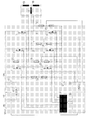
- One of those is schematic in the drawing as a circuit diagram of an inventive Arrangement in which the power stage is formed by three half bridges, shown and below described.
- two MOSFETs form 1, 2; 3, 4; 5, 6 each have a half bridge 7, 8, 9 with exits 10, 11, 12, each of which is connected in a star connection executed windings 13, 14, 15 of a motor connected is.
- the operating voltage Ubat is fed to an input 16, which as U + via a relay 17 of the power stage is fed.
- a current limiting resistor is connected in parallel with the relay 17 18, through which an electrolytic capacitor 19 high capacity can be charged using the relay is only switched on when the voltage U + approximately the voltage Ubat corresponds. This results in an impermissibly high charging current surge avoided. Details of this known circuit are described in DE 100 57 156 A1.
- the arrangement further comprises a control device 20 which known as such in connection with power amplifiers is from a microcomputer or a digital signal processor is formed and as such for understanding the invention need not be explained in more detail.
- Outputs of the Control device 20 are connected to a control circuit 21, which control signals HS1, HS2, HS3, LS1, LS2, LS3 for generated the MOSFETs 1 to 6.
- control device 20 analog / digital converters 20 'are also connected, their inputs generated by a voltage divider 22, 23, 24, 25 Voltages can be supplied.
- the voltage dividers point significantly higher resistance values than the windings 13, 14, 15 in order not to increase the efficiency of the output stage during operation deteriorate.
- a resistor 26 is connected in parallel with the MOSFET 1 together with the voltage divider 23 causes at the output 10 of the half bridge 7 in the case of non-conductive MOSFETs 1, 2 half of the voltage U + is present.
- the voltage dividers 22 to 25 are designed such that at the highest possible value of U + the permissible voltage of CMOS circuits are not exceeded.
- the one from the voltage divider 22 generated voltage is used for the following described individual exams as a tension reference to education the tolerance ranges.
- the MOSFETs 1 are not activated in the first test to 6, so that the output 10 carries the voltage U + / 2, which in the control device 20 taking into account a predetermined one Tolerance is checked. If so, can can be concluded that in the MOSFETs 1, 2 and in the supply line to winding 13 no short circuit to ground 27 or operating voltage U + is present. With error-free power stage are the MOSFETs in this first test 3 to 6 not conductive, so that the windings 13 to 15 the voltages at the outputs 11, 12 as well lie in the medium tolerance range, what from the control device 20 is checked.
- the "upper" MOSFETs 1, 3, 5 switched into the conductive state and thereby each checked whether the outputs 10, 11, 12 a voltage assume that in an upper tolerance range, i.e. in the Is close to the voltage U +.
- the "lower” MOSFETs 2, 4, 6 successively in the conductive Brought condition. It is checked whether the voltage at the outputs 10, 11, 12 in the lower tolerance range, So compared to U +, close to the ground potential lies. From the size of the overshoot or undershoot of the respective tolerance range can depend on the type of defect, for example short circuit or overload.
Landscapes
- Control Of Direct Current Motors (AREA)
- Tests Of Electronic Circuits (AREA)
- Amplifiers (AREA)
Applications Claiming Priority (2)
| Application Number | Priority Date | Filing Date | Title |
|---|---|---|---|
| DE10320926 | 2003-05-09 | ||
| DE10320926A DE10320926A1 (de) | 2003-05-09 | 2003-05-09 | Verfahren und Anordnung zur Prüfung einer Leistungsendstufe |
Publications (3)
| Publication Number | Publication Date |
|---|---|
| EP1475875A2 true EP1475875A2 (fr) | 2004-11-10 |
| EP1475875A3 EP1475875A3 (fr) | 2011-08-17 |
| EP1475875B1 EP1475875B1 (fr) | 2020-07-15 |
Family
ID=32981310
Family Applications (1)
| Application Number | Title | Priority Date | Filing Date |
|---|---|---|---|
| EP04101298.0A Expired - Lifetime EP1475875B1 (fr) | 2003-05-09 | 2004-03-30 | Méthode et dispositif pour vérifier un étage de puissance |
Country Status (4)
| Country | Link |
|---|---|
| US (1) | US7242244B2 (fr) |
| EP (1) | EP1475875B1 (fr) |
| CN (1) | CN100530882C (fr) |
| DE (1) | DE10320926A1 (fr) |
Cited By (2)
| Publication number | Priority date | Publication date | Assignee | Title |
|---|---|---|---|---|
| WO2005060061A3 (fr) * | 2003-12-17 | 2007-01-25 | Siemens Ag | Dispositif pour controler un etage final de puissance |
| EP1876455A1 (fr) * | 2006-07-08 | 2008-01-09 | SEMIKRON Elektronik GmbH & Co. KG | Procédé destiné à la mesure de la résistance d'isolement dans un réseau IT |
Families Citing this family (8)
| Publication number | Priority date | Publication date | Assignee | Title |
|---|---|---|---|---|
| DE10322195A1 (de) | 2003-05-16 | 2004-12-09 | Siemens Ag | Verfahren zur Überwachung einer Leistungsendstufe |
| JP4735325B2 (ja) * | 2006-02-27 | 2011-07-27 | パナソニック電工株式会社 | 電動工具用制御駆動回路 |
| DE102007050298A1 (de) * | 2007-10-22 | 2009-04-23 | Robert Bosch Gmbh | Verfahren zum Erkennen eines Lastabfalls |
| DE102007051004B4 (de) * | 2007-10-26 | 2010-04-08 | Continental Automotive Gmbh | Verfahren zur Vorrichtung zur Detektion und Lokalisierung von Fehlern in einem Umrichter und/oder einer elektrischen Maschine eines elektrischen Antriebs |
| DE102010002993A1 (de) * | 2010-03-18 | 2011-09-22 | Continental Automotive Gmbh | Schaltung für einen bürstenlosen Motor und Verfahren zu deren Betrieb |
| DE102011007222A1 (de) * | 2011-04-12 | 2012-10-18 | Kaco New Energy Gmbh | Wechselrichterschaltung, Wechselrichter und Photovoltaiksystem |
| DE102017223327A1 (de) * | 2017-12-20 | 2019-06-27 | Robert Bosch Gmbh | Verfahren zum Überprüfen einer Endstufe zum Ansteuern einer Last |
| DE102018200717A1 (de) * | 2018-01-17 | 2019-07-18 | Robert Bosch Gmbh | Verfahren zum Test von Brücken einer Endstufe bei drehender Maschine |
Family Cites Families (11)
| Publication number | Priority date | Publication date | Assignee | Title |
|---|---|---|---|---|
| US4459693A (en) * | 1982-01-26 | 1984-07-10 | Genrad, Inc. | Method of and apparatus for the automatic diagnosis of the failure of electrical devices connected to common bus nodes and the like |
| JPS5975167A (ja) * | 1982-10-25 | 1984-04-27 | Hitachi Ltd | 論理回路テスト方式 |
| TW328190B (en) * | 1994-06-14 | 1998-03-11 | Toshiba Co Ltd | Control device of brushless motor and method of fault detection and air conditioner |
| DK172562B1 (da) * | 1995-10-06 | 1999-01-18 | Danfoss As | Fremgangsmåde ved måling af fejlstrømme i en vekselretter, samt vekselretter med styrede halvlederswitche |
| GB9604431D0 (en) * | 1996-03-01 | 1996-05-01 | Lucas Ind Plc | Circuit for testing an electrical actuator drive stage |
| JP3259652B2 (ja) * | 1997-03-11 | 2002-02-25 | 三菱電機株式会社 | 電力変換装置 |
| DE19710319B4 (de) * | 1997-03-13 | 2004-03-25 | Danfoss Drives A/S | Schaltung zum Sperren einer Halbleiterschaltvorrichtung bei Überstrom |
| DE50014492D1 (de) * | 1999-12-06 | 2007-08-30 | Siemens Ag | Verfahren und Schaltungsanordnung zum Einschalten einer Leistungsendstufe |
| DE10041607B4 (de) * | 2000-08-24 | 2006-04-13 | Berger Lahr Gmbh & Co. Kg | Elektrisches Arbeitsgerät sowie Verfahren zu dessen Betreiben |
| US6661285B1 (en) * | 2000-10-02 | 2003-12-09 | Holosonic Research Labs | Power efficient capacitive load driving device |
| JP3896894B2 (ja) * | 2002-05-13 | 2007-03-22 | ソニー株式会社 | 電力増幅装置 |
-
2003
- 2003-05-09 DE DE10320926A patent/DE10320926A1/de not_active Ceased
-
2004
- 2004-03-30 EP EP04101298.0A patent/EP1475875B1/fr not_active Expired - Lifetime
- 2004-05-08 CN CNB2004100456167A patent/CN100530882C/zh not_active Expired - Fee Related
- 2004-05-10 US US10/842,119 patent/US7242244B2/en not_active Expired - Lifetime
Cited By (3)
| Publication number | Priority date | Publication date | Assignee | Title |
|---|---|---|---|---|
| WO2005060061A3 (fr) * | 2003-12-17 | 2007-01-25 | Siemens Ag | Dispositif pour controler un etage final de puissance |
| US7417394B2 (en) | 2003-12-17 | 2008-08-26 | Siemens Aktiengesellschaft | Arrangement for testing a power output stage |
| EP1876455A1 (fr) * | 2006-07-08 | 2008-01-09 | SEMIKRON Elektronik GmbH & Co. KG | Procédé destiné à la mesure de la résistance d'isolement dans un réseau IT |
Also Published As
| Publication number | Publication date |
|---|---|
| EP1475875B1 (fr) | 2020-07-15 |
| US7242244B2 (en) | 2007-07-10 |
| CN1551445A (zh) | 2004-12-01 |
| DE10320926A1 (de) | 2004-12-16 |
| CN100530882C (zh) | 2009-08-19 |
| US20040257017A1 (en) | 2004-12-23 |
| EP1475875A3 (fr) | 2011-08-17 |
Similar Documents
| Publication | Publication Date | Title |
|---|---|---|
| DE4130978C2 (de) | Verfahren zum Prüfen von elektrischen, abgesicherten Verbrauchern in einem Fahrzeug-Bordnetz | |
| DE102011086412B4 (de) | Vorrichtung und Verfahren zum Testen des Zustands der Verbindung einer mit einem Verbindungspunkt verbundenen Last | |
| DE102011004516A1 (de) | Schaltung und Verfahren zur Diagnose von Schaltkontakten in einem batteriebetriebenen Straßenfahrzeug | |
| EP2996899A1 (fr) | Précharge d'un réseau à haute tension d'un véhicule automobile | |
| DE102014220017A1 (de) | Batteriesystem mit einer zum Versorgen eines Hochvoltnetzes mit elektrischer Energie ausgebildeten Batterie und einer Messeinrichtung zum Messen mindestens eines Isolationswiderstandes der Batterie | |
| DE19500452B4 (de) | Verfahren und Vorrichtung zur Überwachung der Funktionsfähigkeit eines Leerlaufstellers | |
| DE102014206694A1 (de) | Vorladeschaltanordnung, Spannungsversorgungsanordnung und Verfahren zum Verbinden eines Verbrauchers mit einer Gleichspannungs-Hochspannungsquelle | |
| DE102011088912A1 (de) | Schaltungsanordnung zur Detektion eines Kurzschlusses bei einer Leistungsschalteranordnung | |
| EP3075048A1 (fr) | Protection contre les surtensions pour réseau de bord de véhicule automobile en cas de délestage | |
| DE102020007868A1 (de) | Verfahren zum Laden eines elektrischen Energiespeichers eines elektrisch angetriebenen Fahrzeugs unter Berücksichtigung einer elektrischen Isolation einer Ladestation, sowie Ladevorrichtung und Fahrzeug | |
| DE10200847B4 (de) | Fehlererfassungseinrichtung einer Kraftstoffeinspritzvorrichtung für eine Brennkraftmaschine mit mehreren Zylindern | |
| EP3452336B1 (fr) | Dispositif de commande multi-tension pour véhicule automobile, véhicule automobile et procédé de fonctionnement du dispositif de commande | |
| WO2009124884A1 (fr) | Procédé et dispositif de détection d'un dysfonctionnement dans un circuit de puissance en pont | |
| EP1475875B1 (fr) | Méthode et dispositif pour vérifier un étage de puissance | |
| DE10359236B3 (de) | Anordnung zur Prüfung einer Leistungsendstufe | |
| DE102021205406B4 (de) | Gleichspannungs-Fehlerstromüberwachung zur Erfassung eines Isolationsfehlers | |
| DE102022002622A1 (de) | Fahrzeug mit einem elektrischen Bordnetz | |
| DE69410431T2 (de) | Fehlerdiagnoseverfahren für die einspritzdüse von hochdruckeinspritzsystemen der brennkraftmaschine | |
| DE102007051004B4 (de) | Verfahren zur Vorrichtung zur Detektion und Lokalisierung von Fehlern in einem Umrichter und/oder einer elektrischen Maschine eines elektrischen Antriebs | |
| DE102021106891A1 (de) | Verfahren zum Überprüfen eines Isolationszustands einer Batterie oder eines Batteriesystems | |
| DE10359235B3 (de) | Verfahren und Anordnung zur Prüfung einer Leistungsendstufe | |
| DE102014004233A1 (de) | Überwachung einer Schirmvorrichtung | |
| DE102017011721A1 (de) | Elektrisches Bordnetz für ein Kraftfahrzeug, wobei für einen Zwischenkreis des elektrischen Bordnetzes eine zusätzliche Gleichspannung bereitgestellt ist | |
| DE102023207285B4 (de) | Schaltervorrichtung und elektrische Heizvorrichtung umfassend die Schaltervorrichtung | |
| DE102024127109B4 (de) | Elektro-Motor-Steuerschaltung, Lenksäule und Verfahren zu deren Betriebszustandsbestimmung |
Legal Events
| Date | Code | Title | Description |
|---|---|---|---|
| PUAI | Public reference made under article 153(3) epc to a published international application that has entered the european phase |
Free format text: ORIGINAL CODE: 0009012 |
|
| AK | Designated contracting states |
Kind code of ref document: A2 Designated state(s): AT BE BG CH CY CZ DE DK EE ES FI FR GB GR HU IE IT LI LU MC NL PL PT RO SE SI SK TR |
|
| AX | Request for extension of the european patent |
Extension state: AL LT LV MK |
|
| RAP1 | Party data changed (applicant data changed or rights of an application transferred) |
Owner name: CONTINENTAL AUTOMOTIVE GMBH |
|
| PUAL | Search report despatched |
Free format text: ORIGINAL CODE: 0009013 |
|
| AK | Designated contracting states |
Kind code of ref document: A3 Designated state(s): AT BE BG CH CY CZ DE DK EE ES FI FR GB GR HU IE IT LI LU MC NL PL PT RO SE SI SK TR |
|
| AX | Request for extension of the european patent |
Extension state: AL LT LV MK |
|
| RIC1 | Information provided on ipc code assigned before grant |
Ipc: H02H 7/122 20060101AFI20110711BHEP |
|
| 17P | Request for examination filed |
Effective date: 20120217 |
|
| AKX | Designation fees paid |
Designated state(s): DE FR GB IT |
|
| 17Q | First examination report despatched |
Effective date: 20120502 |
|
| STAA | Information on the status of an ep patent application or granted ep patent |
Free format text: STATUS: EXAMINATION IS IN PROGRESS |
|
| REG | Reference to a national code |
Ref country code: DE Ref legal event code: R079 Ref document number: 502004015868 Country of ref document: DE Free format text: PREVIOUS MAIN CLASS: H02H0007122000 Ipc: H02H0007080000 |
|
| GRAP | Despatch of communication of intention to grant a patent |
Free format text: ORIGINAL CODE: EPIDOSNIGR1 |
|
| STAA | Information on the status of an ep patent application or granted ep patent |
Free format text: STATUS: GRANT OF PATENT IS INTENDED |
|
| RIC1 | Information provided on ipc code assigned before grant |
Ipc: G01R 31/40 20200101ALI20200127BHEP Ipc: H02H 7/08 20060101AFI20200127BHEP |
|
| INTG | Intention to grant announced |
Effective date: 20200228 |
|
| GRAS | Grant fee paid |
Free format text: ORIGINAL CODE: EPIDOSNIGR3 |
|
| GRAA | (expected) grant |
Free format text: ORIGINAL CODE: 0009210 |
|
| STAA | Information on the status of an ep patent application or granted ep patent |
Free format text: STATUS: THE PATENT HAS BEEN GRANTED |
|
| AK | Designated contracting states |
Kind code of ref document: B1 Designated state(s): DE FR GB IT |
|
| REG | Reference to a national code |
Ref country code: GB Ref legal event code: FG4D Free format text: NOT ENGLISH |
|
| REG | Reference to a national code |
Ref country code: DE Ref legal event code: R096 Ref document number: 502004015868 Country of ref document: DE |
|
| RAP2 | Party data changed (patent owner data changed or rights of a patent transferred) |
Owner name: CONTINENTAL AUTOMOTIVE GMBH |
|
| REG | Reference to a national code |
Ref country code: DE Ref legal event code: R097 Ref document number: 502004015868 Country of ref document: DE |
|
| PG25 | Lapsed in a contracting state [announced via postgrant information from national office to epo] |
Ref country code: IT Free format text: LAPSE BECAUSE OF FAILURE TO SUBMIT A TRANSLATION OF THE DESCRIPTION OR TO PAY THE FEE WITHIN THE PRESCRIBED TIME-LIMIT Effective date: 20200715 |
|
| PLBE | No opposition filed within time limit |
Free format text: ORIGINAL CODE: 0009261 |
|
| STAA | Information on the status of an ep patent application or granted ep patent |
Free format text: STATUS: NO OPPOSITION FILED WITHIN TIME LIMIT |
|
| 26N | No opposition filed |
Effective date: 20210416 |
|
| REG | Reference to a national code |
Ref country code: DE Ref legal event code: R119 Ref document number: 502004015868 Country of ref document: DE |
|
| GBPC | Gb: european patent ceased through non-payment of renewal fee |
Effective date: 20210330 |
|
| PG25 | Lapsed in a contracting state [announced via postgrant information from national office to epo] |
Ref country code: FR Free format text: LAPSE BECAUSE OF NON-PAYMENT OF DUE FEES Effective date: 20210331 Ref country code: GB Free format text: LAPSE BECAUSE OF NON-PAYMENT OF DUE FEES Effective date: 20210330 Ref country code: DE Free format text: LAPSE BECAUSE OF NON-PAYMENT OF DUE FEES Effective date: 20211001 |