EP1475989A1 - Connecteur pour microphone - Google Patents
Connecteur pour microphone Download PDFInfo
- Publication number
- EP1475989A1 EP1475989A1 EP03010189A EP03010189A EP1475989A1 EP 1475989 A1 EP1475989 A1 EP 1475989A1 EP 03010189 A EP03010189 A EP 03010189A EP 03010189 A EP03010189 A EP 03010189A EP 1475989 A1 EP1475989 A1 EP 1475989A1
- Authority
- EP
- European Patent Office
- Prior art keywords
- microphone
- ring
- connector
- constrict
- cable
- Prior art date
- Legal status (The legal status is an assumption and is not a legal conclusion. Google has not performed a legal analysis and makes no representation as to the accuracy of the status listed.)
- Withdrawn
Links
Images


Classifications
-
- H—ELECTRICITY
- H01—ELECTRIC ELEMENTS
- H01R—ELECTRICALLY-CONDUCTIVE CONNECTIONS; STRUCTURAL ASSOCIATIONS OF A PLURALITY OF MUTUALLY-INSULATED ELECTRICAL CONNECTING ELEMENTS; COUPLING DEVICES; CURRENT COLLECTORS
- H01R13/00—Details of coupling devices of the kinds covered by groups H01R12/70 or H01R24/00 - H01R33/00
- H01R13/58—Means for relieving strain on wire connection, e.g. cord grip, for avoiding loosening of connections between wires and terminals within a coupling device terminating a cable
- H01R13/59—Threaded ferrule or bolt operating in a direction parallel to the cable or wire
-
- H—ELECTRICITY
- H04—ELECTRIC COMMUNICATION TECHNIQUE
- H04R—LOUDSPEAKERS, MICROPHONES, GRAMOPHONE PICK-UPS OR LIKE ACOUSTIC ELECTROMECHANICAL TRANSDUCERS; ELECTRIC HEARING AIDS; PUBLIC ADDRESS SYSTEMS
- H04R1/00—Details of transducers, loudspeakers or microphones
- H04R1/08—Mouthpieces; Microphones; Attachments therefor
Definitions
- This invention relates to a microphone connector, particularly to one capable to prevent the microphone connector from randomly separating from a microphone, and really keep the microphone from falling off the connector to cause damage to the microphone.
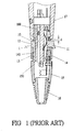
- a first conventional microphone connector shown in Fig. 1 includes a body 1, a terminal base 10 provided in the body 1 for receiving terminals 100, an elastic hook 11 combined on the body 1, a stop annular wall 12 formed integral with the body 1, male threads 13 formed on the stop annular wall 12, a constrict ring 14 having female threads 140 to engage with the male threads 13 to combine with the body 1, and a rear body 15 having female threads 150 to engage with the body 1 and a cable constrictor 16 for constrict a cable.
- the constrict ring 14 can prevent the elastic hook 11 from pressed.
- the first conventional microphone connector has the body 1 provided with the stop annular wall 12, which may form a gap (d) between the connector and a microphone 17 after the microphone 17 is connected with the connector.
- This gap may hamper mutual tight combination of the both so that the microphone may sway owing to the gap (d), and subsequently fall off the connector to be damaged. Further the gap (d) forces the combined state of the microphone and the connector slant to look like untidy
- a second conventional microphone connector shown in Fig. 2 includes a body 2, a terminal base 20 for receiving terminals 200, an elastic hook 21 provided on the body 2, male threads 23, a constrict ring 24 having female threads 240 and a sloping surface 241 extending rearward from the male threads 240, and an inner annular surface 242 of a larger diameter extending rearward from the sloping surface 241. Then the constrict ring 24 threadably engages with the body 2 with the elastic hook 21 positioned in the constrict ring 24 so that the constrict ring 24 may move forward after a microphone is combined with the connector with the inner annular surface 242 forcing the elastic hook 21 tightly hook the microphone 17. Then the microphone 17 may be closely combined with the connector.
- a rear fixing base 25 of the connector can be used for locking the connector on a flat surface of something like a table.
- the second conventional microphone connector can keep a microphone in a stable condition, with the constrict ring 24, but it is more suitable for a fix-style microphone, and its elastic hook 21 may soon lose its elasticity by frequent use, possibly causing the microphone to fall off the connector.
- the microphone connector has the following features.
- a preferred embodiment of a microphone connector in the present invention includes a body 3, a terminal base 5, a cable constrictor 6, a compress ring 7, a rotatable constrict ring 8 and a rear body 9 as main components combined together.
- the body 3 is provided integral with an intermediate guide annular wall 30 having two lateral guide projecting edges 300 and a rear male threaded portion 31 behind the intermediate guide annular wall 3 to engage with a rotatable constrict ring 8 and a rear body 9.
- An elastic hook 32 is combined on the body 3, having a front-end portion 320 to combine with a microphone 4 or another connector.
- the elastic hook 32 has elasticity for opening and closing in conjunction with the elastic members 321 fixed on the terminal base 5 to move with the elastic hook 32 to supply the elastic hook 32 with elasticity.
- the body 3 has a center hole 33 for receiving the terminal base 5 therein.
- the terminal base 5 has a plurality of terminals 50, fitted stably in the center hole 33 of the body 3, with the terminals 50 having their ends welded with lead wires.
- the cable constrictor 6 has a front annular wall 60 of multi-sides and with a round inner hole of a glossy surface, and the front annular wall 60 has a lateral gap 61 for receiving an end of a terminal 50 of the terminal base 5, an intermediate annular wall 62 of a small diameter behind the rear annular wall 60, and a rear tapering annular wall 63 having an inner toothed surface 630 advantageous for constricting a cable.
- the intermediate and the rear sloping annular wall 62 and 63 are consisted respectively of six pinching posts 64, which can reduce anti-expansion force to save force in constricting a cable.
- the intermediate annular wall 62 is recessed so that its inner surface may partly contact with the outer surface of a cable and subsequently more tightly constricting the cable by means of surface contact.
- the compress ring 7 has a center hole 70 to fit around the annular guide wall 30 of the body 3, a lateral gap 71 for receiving a lower portion of the elastic hook 32 therein to permit the elastic hook 32 to move back and forth therein.
- the compress ring 7 further has two opposite lateral guide grooves 72 formed in an inner annular surface to fit with the lateral guide projecting edges 300 of the body 3 to let the compress ring 7 move in a definite direction, and a small diameter annular edge 73 formed in the inner annular surface to limit the moving distance of the compress ring 7.
- the rotatable constrict ring 8 has partial female threads 80 to engage with the male threads 31 of the body 3.
- the rotatable constrict ring 8 When the rotatable constrict ring 8 is rotated after combined with the body 3, it force the compress ring 7 move inward to closely contact the rear end of a microphone 4, leaving no gap at all, as shown in Fig. 5. Then the connector can tightly combine with the microphone 4, with the elastic hook 32 no longer able to be pressed, preventing the microphone 4 from separating from the connector.
- the rotatable constrict ring 8 has a threaded hole 81 through the annular wall for a screw 82 to screw therein to lock the connector with the microphone 4 after combined together and limit rotation of the rotatable constrict ring and preventing the microphone 4 from separating from the connector at random.
- the rear body 9 has female threads to engage with the body 3, and a constrict member 90 formed in an outer end for constricting a cable.
- the microphone connector in the invention utilizes the rotatable constrict ring 8 to produce tightening function to effect close combination of a connector with a microphone, at the same time preventing the elastic hook from incidentally pressed so as not to let a microphone separate at random from the connector and also to lengthen service life of a microphone.
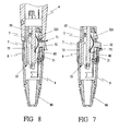
- Figs. 6, 7 and 8 show a second embodiment of a microphone connector in the invention, which includes a body 3, a terminal base 5, a compress ring 7, a rotatable ring 8 and a rear body 9 as main components combined together, without the cable constrictor 6 in the first embodiment.
- the body 3 is provided integral with an intermediate guide annular wall 30 having two opposite lateral guide projecting edges 300 and a rear male threaded wall 31 to threadably combine with the rotatable constrict ring 8 and the rear body 9, and an elastic hook 32 with a front end portion 320 to combine with a microphone 4 or another connector.
- the elastic hook 32 has elasticity for closing and opening in conjunction with the elastic members 320 fixed on the terminal base 5, and the body 3 has a center hole 33 for receiving the terminal base 5 therein.
- the terminal base 5 has a plurality of terminals 50, inserted in the center hole 33 of the body 3 from one side, with the terminals 50 having their ends welded with lead wires.
- the compress ring 7 has a center hole 70 to fit around the guide annular wall 30 of the body 3, having a lateral gap 71 for receiving the lower portion of the elastic hook 32 therein to permit the elastic hook 32 to move back and forth therein.
- the compress ring 7 further has two opposite inner lateral guide grooves 72 to fit with the two lateral guide projecting edges 300 of the body 3 to let the compress ring 7 move in the definite direction, and a small diameter inner annular surface 73 to limit the moving distance of the compress ring 7.
- the rotatable constrict ring 8 has partial female threads 80 to engage with the male threads 31 of the body 3.
- the rotatable constrict ring 8 When the rotatable constrict ring 8 is rotated after engaged with the body 3, it can force the compress ring 7 to move forward and tightly contact with the rear end of a microphone 4, leaving no gap between them at all, as shown in Fig. 8. Therefore, the connector and the microphone 4 are combined tightly together, with the elastic hook 32 no longer able to be pressed, preventing the microphone 4 from separating from the connector randomly.
- the rotatable ring 8 has a threaded hole through its annular wall for a screw 82 to lock the connector with the microphone 4, limiting rotation of the rotatable constrict ring 8 and preventing the microphone 4 from separating from the connector at random.
- the rear body 9 has female threads to engage with the body 3, and a constrict member 90 formed in its outer end for tightly catching a cable.
- the second embodiment of a microphone connector also utilizes the movable constrict ring 8 for forcing the compress ring 7 closely contact the rear end of a microphone 4 so that the microphone and the connetor are closely and tightly combined together, not only preventing the elastic hook not incidentally pressed but also hampering the microphone separate from the connector randomly, lengthening service life of a microphone.
Landscapes
- Details Of Audible-Bandwidth Transducers (AREA)
Priority Applications (2)
| Application Number | Priority Date | Filing Date | Title |
|---|---|---|---|
| US10/408,698 US6814601B2 (en) | 2003-04-04 | 2003-04-04 | Microphone connector |
| EP03010189A EP1475989A1 (fr) | 2003-04-04 | 2003-05-06 | Connecteur pour microphone |
Applications Claiming Priority (2)
| Application Number | Priority Date | Filing Date | Title |
|---|---|---|---|
| US10/408,698 US6814601B2 (en) | 2003-04-04 | 2003-04-04 | Microphone connector |
| EP03010189A EP1475989A1 (fr) | 2003-04-04 | 2003-05-06 | Connecteur pour microphone |
Publications (1)
| Publication Number | Publication Date |
|---|---|
| EP1475989A1 true EP1475989A1 (fr) | 2004-11-10 |
Family
ID=33492138
Family Applications (1)
| Application Number | Title | Priority Date | Filing Date |
|---|---|---|---|
| EP03010189A Withdrawn EP1475989A1 (fr) | 2003-04-04 | 2003-05-06 | Connecteur pour microphone |
Country Status (2)
| Country | Link |
|---|---|
| US (1) | US6814601B2 (fr) |
| EP (1) | EP1475989A1 (fr) |
Cited By (2)
| Publication number | Priority date | Publication date | Assignee | Title |
|---|---|---|---|---|
| WO2009126411A1 (fr) * | 2008-04-09 | 2009-10-15 | 3M Innovative Properties Company | Dispositif d'entrée de câble de télécommunications |
| US10005431B2 (en) | 2011-04-21 | 2018-06-26 | Pylon Manufacturing Corp. | Vortex damping wiper blade |
Families Citing this family (12)
| Publication number | Priority date | Publication date | Assignee | Title |
|---|---|---|---|---|
| JP4344657B2 (ja) * | 2004-06-30 | 2009-10-14 | 株式会社オーディオテクニカ | コンデンサマイクロホン |
| USD521931S1 (en) * | 2004-11-01 | 2006-05-30 | Leviton Manufacturing Co., Inc. | Latching single cam connector |
| DE102007009947B4 (de) * | 2007-03-01 | 2016-11-24 | Techpointe S.A. | Steckerelement |
| JP2009259560A (ja) * | 2008-04-16 | 2009-11-05 | Audio Technica Corp | 電気機器用コネクタおよびその製造方法とコンデンサマイクロホン |
| JP5586054B2 (ja) * | 2010-08-27 | 2014-09-10 | 株式会社オーディオテクニカ | マイクロホンのコネクタ |
| WO2013152261A1 (fr) * | 2012-04-05 | 2013-10-10 | Molex Incorporated | Connecteur électrique haute puissance |
| WO2015116967A1 (fr) * | 2014-01-31 | 2015-08-06 | Ideal Industries, Inc. | Connecteur à enficher |
| US10749287B2 (en) | 2018-08-08 | 2020-08-18 | Shure Acquisition Holdings, Inc. | Connection assembly for audio equipment |
| US10522946B1 (en) * | 2018-09-17 | 2019-12-31 | Hewlett Packard Enterprise Development Lp | Connectors with locking tab |
| US10770840B1 (en) * | 2019-06-14 | 2020-09-08 | Aptiv Technologies Limited | Shielded electrical connector assembly |
| AT524374A1 (de) * | 2020-11-03 | 2022-05-15 | Neutrik Ag | Steckeranordnung |
| USD1089122S1 (en) * | 2023-06-30 | 2025-08-19 | Karim Messadek | XLR connector |
Citations (3)
| Publication number | Priority date | Publication date | Assignee | Title |
|---|---|---|---|---|
| US2081622A (en) * | 1935-04-17 | 1937-05-25 | Turner Company | Microphone plug |
| EP0884807A1 (fr) * | 1997-06-09 | 1998-12-16 | New Tide Enterprise Co., Ltd. | Connecteur pour microphone |
| US6116945A (en) * | 1997-12-30 | 2000-09-12 | The Whitaker Corporation | Microphone connector assembly |
Family Cites Families (5)
| Publication number | Priority date | Publication date | Assignee | Title |
|---|---|---|---|---|
| DE2840728C2 (de) * | 1978-09-19 | 1980-09-04 | Georg Dipl.-Ing. Dr.-Ing. 8152 Feldkirchen-Westerham Spinner | HF-Koaxialsteckverbindung |
| US4422710A (en) * | 1981-12-21 | 1983-12-27 | The United States Of America As Represented By The Secretary Of The Navy | Repairable backshell adapter for electrical connector |
| DE3218677C2 (de) * | 1982-05-18 | 1985-12-12 | Robert Bosch Gmbh, 7000 Stuttgart | Elektrische Steckverbinderanordnung |
| US6086400A (en) * | 1997-10-17 | 2000-07-11 | Electro Adapter, Inc. | Self-locking cable connector coupling |
| US6113410A (en) * | 1998-10-27 | 2000-09-05 | Lucent Technologies Inc. | RF connector lock |
-
2003
- 2003-04-04 US US10/408,698 patent/US6814601B2/en not_active Expired - Fee Related
- 2003-05-06 EP EP03010189A patent/EP1475989A1/fr not_active Withdrawn
Patent Citations (3)
| Publication number | Priority date | Publication date | Assignee | Title |
|---|---|---|---|---|
| US2081622A (en) * | 1935-04-17 | 1937-05-25 | Turner Company | Microphone plug |
| EP0884807A1 (fr) * | 1997-06-09 | 1998-12-16 | New Tide Enterprise Co., Ltd. | Connecteur pour microphone |
| US6116945A (en) * | 1997-12-30 | 2000-09-12 | The Whitaker Corporation | Microphone connector assembly |
Cited By (5)
| Publication number | Priority date | Publication date | Assignee | Title |
|---|---|---|---|---|
| WO2009126411A1 (fr) * | 2008-04-09 | 2009-10-15 | 3M Innovative Properties Company | Dispositif d'entrée de câble de télécommunications |
| CN101981760A (zh) * | 2008-04-09 | 2011-02-23 | 3M创新有限公司 | 通信电缆入口设备 |
| US8313250B2 (en) | 2008-04-09 | 2012-11-20 | 3M Innovative Properties Company | Telecommunications cable inlet device |
| CN101981760B (zh) * | 2008-04-09 | 2014-03-26 | 3M创新有限公司 | 通信电缆入口设备 |
| US10005431B2 (en) | 2011-04-21 | 2018-06-26 | Pylon Manufacturing Corp. | Vortex damping wiper blade |
Also Published As
| Publication number | Publication date |
|---|---|
| US20040198087A1 (en) | 2004-10-07 |
| US6814601B2 (en) | 2004-11-09 |
Similar Documents
| Publication | Publication Date | Title |
|---|---|---|
| US6814601B2 (en) | Microphone connector | |
| EP0891644B1 (fr) | Dispositif de verrouillage pour connecteur | |
| US5276280A (en) | Electrical cable connector | |
| US8119933B2 (en) | Duplex electrical connector with frustro-conical retaining ring and crimped inlet end | |
| US4932897A (en) | Connector for an electrical signal transmitting cable | |
| EP2101373B1 (fr) | Connecteur de compression doté d'une prise de dérivation pour accueillir des câbles de dérivation de différentes tailles dans une seule de prise de dérivation | |
| US20110312199A1 (en) | Coaxial connectors having backwards compatability with f-style female connector ports and related female connector ports, adapters and methods | |
| WO2004095641A3 (fr) | Connecteur de courant de secteur de type a compression | |
| US7201604B1 (en) | Ethernet cable connector and methods of use thereof | |
| CA2538285A1 (fr) | Systeme de raccord de tuyau porteur de courant d'aspirateur | |
| EP1403973A3 (fr) | Connecteur pour un module | |
| CA2486210A1 (fr) | Adaptateur de connecteur optique avec une piece d'accouplement ajustable en utilisant une fente | |
| JP5649753B1 (ja) | モジュラープラグ内蔵プラグ組立体及びモジュラーコネクタ内蔵コネクタ組立体 | |
| US6846989B2 (en) | Multi-tap compression connector | |
| CN102651524A (zh) | 一种抗拉型推拉锁紧插头及使用该插头的电连接器组件 | |
| US6071155A (en) | Electrical wire mounting structure | |
| US20060166554A1 (en) | Waterproof device for electrical connector | |
| US7063558B1 (en) | Electric plug | |
| US7867002B1 (en) | Wire connector | |
| US4269472A (en) | Electrical terminal | |
| KR20160143484A (ko) | 방수 케이블 커넥터 | |
| GB2375438A (en) | Anti-decoupling mechanism for a threaded coupling connector | |
| US6672903B1 (en) | Signal-line connector | |
| US5354213A (en) | Adjustable electrical cord clamp | |
| US5810621A (en) | Two-piece construction bulb socket |
Legal Events
| Date | Code | Title | Description |
|---|---|---|---|
| PUAI | Public reference made under article 153(3) epc to a published international application that has entered the european phase |
Free format text: ORIGINAL CODE: 0009012 |
|
| AK | Designated contracting states |
Kind code of ref document: A1 Designated state(s): AT BE BG CH CY CZ DE DK EE ES FI FR GB GR HU IE IT LI LU MC NL PT RO SE SI SK TR |
|
| AX | Request for extension of the european patent |
Extension state: AL LT LV MK |
|
| 17P | Request for examination filed |
Effective date: 20050215 |
|
| AKX | Designation fees paid |
Designated state(s): CH DE GB LI NL |
|
| STAA | Information on the status of an ep patent application or granted ep patent |
Free format text: STATUS: THE APPLICATION IS DEEMED TO BE WITHDRAWN |
|
| 18D | Application deemed to be withdrawn |
Effective date: 20091201 |