EP1476003A2 - Circuit d'alimentation et méthode pour l'alimentation de lampes à décharge gazeuse - Google Patents
Circuit d'alimentation et méthode pour l'alimentation de lampes à décharge gazeuse Download PDFInfo
- Publication number
- EP1476003A2 EP1476003A2 EP04008068A EP04008068A EP1476003A2 EP 1476003 A2 EP1476003 A2 EP 1476003A2 EP 04008068 A EP04008068 A EP 04008068A EP 04008068 A EP04008068 A EP 04008068A EP 1476003 A2 EP1476003 A2 EP 1476003A2
- Authority
- EP
- European Patent Office
- Prior art keywords
- lamp
- control device
- gas discharge
- operating
- limit value
- Prior art date
- Legal status (The legal status is an assumption and is not a legal conclusion. Google has not performed a legal analysis and makes no representation as to the accuracy of the status listed.)
- Granted
Links
Images


Classifications
-
- H—ELECTRICITY
- H05—ELECTRIC TECHNIQUES NOT OTHERWISE PROVIDED FOR
- H05B—ELECTRIC HEATING; ELECTRIC LIGHT SOURCES NOT OTHERWISE PROVIDED FOR; CIRCUIT ARRANGEMENTS FOR ELECTRIC LIGHT SOURCES, IN GENERAL
- H05B41/00—Circuit arrangements or apparatus for igniting or operating discharge lamps
- H05B41/14—Circuit arrangements
- H05B41/26—Circuit arrangements in which the lamp is fed by power derived from DC by means of a converter, e.g. by high-voltage DC
- H05B41/28—Circuit arrangements in which the lamp is fed by power derived from DC by means of a converter, e.g. by high-voltage DC using static converters
- H05B41/288—Circuit arrangements in which the lamp is fed by power derived from DC by means of a converter, e.g. by high-voltage DC using static converters with semiconductor devices and specially adapted for lamps without preheating electrodes, e.g. for high-intensity discharge lamps, high-pressure mercury or sodium lamps or low-pressure sodium lamps
- H05B41/2881—Load circuits; Control thereof
- H05B41/2882—Load circuits; Control thereof the control resulting from an action on the static converter
- H05B41/2883—Load circuits; Control thereof the control resulting from an action on the static converter the controlled element being a DC/AC converter in the final stage, e.g. by harmonic mode starting
-
- B—PERFORMING OPERATIONS; TRANSPORTING
- B42—BOOKBINDING; ALBUMS; FILES; SPECIAL PRINTED MATTER
- B42D—BOOKS; BOOK COVERS; LOOSE LEAVES; PRINTED MATTER CHARACTERISED BY IDENTIFICATION OR SECURITY FEATURES; PRINTED MATTER OF SPECIAL FORMAT OR STYLE NOT OTHERWISE PROVIDED FOR; DEVICES FOR USE THEREWITH AND NOT OTHERWISE PROVIDED FOR; MOVABLE-STRIP WRITING OR READING APPARATUS
- B42D25/00—Information-bearing cards or sheet-like structures characterised by identification or security features; Manufacture thereof
- B42D25/20—Information-bearing cards or sheet-like structures characterised by identification or security features; Manufacture thereof characterised by a particular use or purpose
- B42D25/27—Lots, e.g. lottery tickets
-
- B—PERFORMING OPERATIONS; TRANSPORTING
- B42—BOOKBINDING; ALBUMS; FILES; SPECIAL PRINTED MATTER
- B42D—BOOKS; BOOK COVERS; LOOSE LEAVES; PRINTED MATTER CHARACTERISED BY IDENTIFICATION OR SECURITY FEATURES; PRINTED MATTER OF SPECIAL FORMAT OR STYLE NOT OTHERWISE PROVIDED FOR; DEVICES FOR USE THEREWITH AND NOT OTHERWISE PROVIDED FOR; MOVABLE-STRIP WRITING OR READING APPARATUS
- B42D15/00—Printed matter of special format or style not otherwise provided for
- B42D15/0053—Forms specially designed for commercial use, e.g. bills, receipts, offer or order sheets, coupons
-
- H—ELECTRICITY
- H05—ELECTRIC TECHNIQUES NOT OTHERWISE PROVIDED FOR
- H05B—ELECTRIC HEATING; ELECTRIC LIGHT SOURCES NOT OTHERWISE PROVIDED FOR; CIRCUIT ARRANGEMENTS FOR ELECTRIC LIGHT SOURCES, IN GENERAL
- H05B41/00—Circuit arrangements or apparatus for igniting or operating discharge lamps
- H05B41/14—Circuit arrangements
- H05B41/26—Circuit arrangements in which the lamp is fed by power derived from DC by means of a converter, e.g. by high-voltage DC
- H05B41/28—Circuit arrangements in which the lamp is fed by power derived from DC by means of a converter, e.g. by high-voltage DC using static converters
- H05B41/288—Circuit arrangements in which the lamp is fed by power derived from DC by means of a converter, e.g. by high-voltage DC using static converters with semiconductor devices and specially adapted for lamps without preheating electrodes, e.g. for high-intensity discharge lamps, high-pressure mercury or sodium lamps or low-pressure sodium lamps
- H05B41/292—Arrangements for protecting lamps or circuits against abnormal operating conditions
- H05B41/2921—Arrangements for protecting lamps or circuits against abnormal operating conditions for protecting the circuit against abnormal operating conditions
- H05B41/2925—Arrangements for protecting lamps or circuits against abnormal operating conditions for protecting the circuit against abnormal operating conditions against abnormal lamp operating conditions
-
- H—ELECTRICITY
- H05—ELECTRIC TECHNIQUES NOT OTHERWISE PROVIDED FOR
- H05B—ELECTRIC HEATING; ELECTRIC LIGHT SOURCES NOT OTHERWISE PROVIDED FOR; CIRCUIT ARRANGEMENTS FOR ELECTRIC LIGHT SOURCES, IN GENERAL
- H05B41/00—Circuit arrangements or apparatus for igniting or operating discharge lamps
- H05B41/14—Circuit arrangements
- H05B41/36—Controlling
- H05B41/38—Controlling the intensity of light
- H05B41/382—Controlling the intensity of light during the transitional start-up phase
- H05B41/386—Controlling the intensity of light during the transitional start-up phase for speeding-up the lighting-up
-
- H—ELECTRICITY
- H05—ELECTRIC TECHNIQUES NOT OTHERWISE PROVIDED FOR
- H05B—ELECTRIC HEATING; ELECTRIC LIGHT SOURCES NOT OTHERWISE PROVIDED FOR; CIRCUIT ARRANGEMENTS FOR ELECTRIC LIGHT SOURCES, IN GENERAL
- H05B41/00—Circuit arrangements or apparatus for igniting or operating discharge lamps
- H05B41/14—Circuit arrangements
- H05B41/36—Controlling
- H05B41/38—Controlling the intensity of light
- H05B41/382—Controlling the intensity of light during the transitional start-up phase
- H05B41/388—Controlling the intensity of light during the transitional start-up phase for a transition from glow to arc
-
- Y—GENERAL TAGGING OF NEW TECHNOLOGICAL DEVELOPMENTS; GENERAL TAGGING OF CROSS-SECTIONAL TECHNOLOGIES SPANNING OVER SEVERAL SECTIONS OF THE IPC; TECHNICAL SUBJECTS COVERED BY FORMER USPC CROSS-REFERENCE ART COLLECTIONS [XRACs] AND DIGESTS
- Y02—TECHNOLOGIES OR APPLICATIONS FOR MITIGATION OR ADAPTATION AGAINST CLIMATE CHANGE
- Y02B—CLIMATE CHANGE MITIGATION TECHNOLOGIES RELATED TO BUILDINGS, e.g. HOUSING, HOUSE APPLIANCES OR RELATED END-USER APPLICATIONS
- Y02B20/00—Energy efficient lighting technologies, e.g. halogen lamps or gas discharge lamps
Definitions
- the invention relates to an operating device and a method for operating gas discharge lamps with electrodes.
- the invention solves problems that occur when starting gas discharge lamps.
- Gas discharge lamps must be lit by a high voltage. After the ignition the lamp heats up from a start temperature during a start-up phase to an operating temperature.
- the voltage after ignition on a gas discharge lamp is called burning voltage and is not within wide limits depends essentially on the lamp current.
- the burning voltage increases during the start-up phase from a starting voltage to an operating voltage.
- the start-up phase closes when the gas discharge lamps function as intended an operating phase.
- high and low pressure gas discharge lamps distinguished.
- high-pressure gas discharge lamps also referred to below as lamps
- lamps is essential for the functionality that during the start-up phase Pressure in the lamp vessel increases from an initial pressure to an operating pressure. This is one reason why the invention described below is special can advantageously be used in high-pressure gas discharge lamps. however use with low pressure gas discharge lamps is also possible.
- the operating device During the operating phase, it is common for the operating device to have the performance of the Lamp regulates to a target power. Since the operating voltage during the start-up phase low, would be a high one with pure power control during the start-up phase Lamp current required to set the target power. This current can be many times be higher than the lamp current during the operating phase. This would be too lead to destruction of the lamp electrodes. Therefore, in the prior art the current that the control gear supplies to the lamp during the start-up phase limited to a constant starting current. So at least during one In the first section of the start-up phase, the lamp is fed with the constant starting current. The internal voltage increases during the start-up phase. Reaches the burning voltage a value of the desired power, together with the constant current results, the power regulation begins to work.
- the start-up phase is complete when the operating voltage has reached the value of the operating operating voltage.
- the Operational burning voltage shows sample variations and also changes during the life of a lamp.
- the operating burning voltage is therefore defined by the operating voltage, which is essentially the case for nominal power during a time range remains constant.
- the time range to be considered is, for example Minute.
- Correlated with the operating voltage is an operating lamp current that together with the operating combustion voltage gives the target power.
- the starting current is selected to reliably rule out this case, which is significantly higher than the operating lamp current. This is documented in US 5,083,065 (Sakata).
- One aspect when choosing the starting current is also the desire for a start-up phase that is as short as possible, in the shortest possible time to achieve a target luminous flux.
- a high starting current places a heavy load on the electrodes, which leads to Damage to the electrodes leads and thus reduces the life of a lamp.
- the electrodes are damaged either by overheating, which leads to melting and burns or by so-called sputtering, which is caused Ions hitting an electrode at high speed.
- the starting phase begins with a low starting current, the Value is chosen so that damage to the electrodes of a connected Lamp is excluded. With the starting current initially set, none The lamp reaches the state in which the lamp consumes the desired power according to the invention, the starting current is increased.
- Figure 1 is a block diagram of an embodiment of an inventive Operating device shown for the operation of high-pressure gas discharge lamps is blessed.
- the basic structure and the basic Operation of such an operating device is described in WO 95/35645 (Derra).
- the individual blocks are briefly described below.
- Block 1 contains a DC power supply that uses its energy in general draws from a mains voltage supply.
- the value of the DC voltage supplied lies above the operating voltage of a connected lamp 6.
- the DC voltage supply feeds a step-down converter 2, which is the same as that of the DC voltage supply delivered voltage value transformed to a value that corresponds to the operating voltage of a connected lamp 6.
- the step-down converter 2 contains an actuator with which the lamp current can be adjusted. This happens by choosing the voltage set at the output of the buck converter becomes.
- PWM pulse width modulation
- the design of the buck converter 2 can be found in the general literature on power electronics be removed.
- WO 95/35645 (Derra) describes a topology with a Switch selected. However, it is also a version with multiple switches possible as z. B. represents a half-bridge.
- the step-down converter 2 contains a choke, which serves as a current limitation. The step-down converter 2 thus has a characteristic which corresponds to an adjustable current source for the lamp current.
- the step-down converter 2 supplies a direct current or one AC.
- the output of the buck converter 2 is fed into a rectifier 3, which is connected to its Output provides a direct current.
- the rectifier 3 can be omitted if the step-down converter 2 supplies a direct current.
- the direct current from the rectifier 3 or the step-down converter 2 is converted into a full bridge 4 fed the direct current into a rectangular alternating current reshapes.
- the frequency of the rectangular alternating current is compared to usual frequencies at which the step-down converter 2 operates at low values between 50 Hz and 1 kHz.
- the conversion into rectangular alternating current is necessary for applications that operate AC lamps and a uniform one Need luminous flux. Examples of such applications are projectors and Rear projection TV.
- the electrode-gentle startup of the invention Lamp can also be used on DC lamps or on AC lamps be operated with non-rectangular alternating current. ever after use, block 3 or 4 or both can be omitted.
- an ignition unit 5 is connected, which supplies the voltage necessary to ignite the lamp. After ignition of the lamp takes over the ignition unit 5 usually no longer functions.
- a control unit 7 is with the step-down converter 2, the rectifier 3, the full bridge 4 and the ignition unit 5 connected.
- the control unit 7 contains the control device, the control device, the detection device and measuring devices for recording operating parameters (e.g. burning voltage, lamp current) and a device for storing lamp-typical data and characteristic curves.
- operating parameters e.g. burning voltage, lamp current
- a device for storing lamp-typical data and characteristic curves e.g. burning voltage, lamp current
- the Individual devices are summarized in the control unit 7, since the control unit 7 usually contains a microcontroller that functions as multiple or of all facilities united. In many cases, the realization of a Setup possible either by hardware or by software. In increasing Dimensions, control and regulation tasks are taken over by software, since these Solution is inexpensive and flexible.
- All connections leading to the control unit 7 can be both inputs and Exits. Connected as inputs, the connections can provide information about the burning voltage and the lamp current as desired from one of the blocks 2-5 feed the control unit 7.
- control unit 7 Ignition, start-up, operation and shutdown of the control gear.
- the control device which is contained in the control unit 7, calculates from the Lamp current and the burning voltage the lamp power and compares it with a stored target power for the lamp to be operated. Is the lamp power less than the target power, the control device increases via the actuating device the lamp current so long, lamp power and target power match.
- the control device which is in the control unit 7 is contained, via an actuating direction which is contained in the step-down converter 2, after ignition, first enter a limit value for the lamp current.
- the lamp is in the start-up phase, which is why the lamp current is also in this phase Starting current is called.
- the limit value is chosen such that a Damage to the electrodes is excluded. The limit depends on the lamp to be operated. A value usually determined from test series is stored in the control unit 7.
- the limit value can be constant during the start-up phase, which is a simple implementation allows. However, it has been shown that a with regard to the load of the Electrodes and the stability of the plasma arc of the lamp optimized for startup can be if the limit for the lamp current depends on the burning voltage is chosen. The optimal dependency is determined in experiments and stored in the form of a characteristic curve in the control unit 7.
- the control unit 7 thus first determines the by means of a measuring device Burning voltage and sets the associated optimal limit for the lamp current on. During the start-up phase, the internal voltage continues to increase and ideally reaches a value that leads to a lamp power that the target power corresponds and the lamp finally goes into the operating phase. A Change of the constant or of the stored characteristic curve In this ideal case, the limit value is not necessary.
- the lowest possible limit value is selected, that can lead to a case that deviates from the ideal case.
- the performance that in the non-ideal case the lamp is implemented so low that the burning voltage does not rise to such an extent that the lamp achieves the desired output. Much more the burning voltage remains at a value and no longer increases.
- a detection device recognizes this case and emits a signal to the control device. This causes an increase in the limit, whereupon the Burning voltage begins to rise again. A one-off increase is usually sufficient the limit value to bring the lamp into the operating phase. However, it is also possible that the detection device recognizes several times that the lamp the target power will not reach and a further increase in the limit above one Triggers signal to the control device.
- An increase in the limit value can be configured such that the control device the control device a higher based on a constant limit specifies a constant limit. This solution can be easily implemented.
- the control device is also designed in this way that the actuating device has a gradually or continuously increasing Prescribes limit.
- a time measuring device measures the time that has passed since the start of the start-up phase. After a preset time, the detection device sends a signal to the control device.
- the preset time is usually determined by series of tests with the operating lamp determined. After the preset time the lamp has the If the target power has not yet been reached, the control device uses a higher one Limit effective. Does the lamp have the desired output after the preset time already reached, the control device would indeed have a higher lamp current allow, however, the control device sets a lamp current that together with the operating voltage results in the target power.
- Another option for executing the detection device is to that the detection device detects the rise in the operating voltage.
- the detection device sends a signal to the control device.
- the specified value for the increase in the operating voltage is in usually determined by series of tests with the lamp to be operated. Across from the version of the detection device described first has the second Execution the advantage that it can recognize earlier that a set Limit is too low and the start-up phase can be shortened.
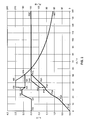
- FIG. 2 shows an example of a diagram showing the dependence of the lamp current and shows the lamp power from the burning voltage. Are shown two cases with different start-up behavior, controlled by two different ones Characteristics.
- the operating voltage UL is given in volts on the abscissa. On the left ordinate is the lamp current IL in amperes and the lamp power on the right ordinate PL stated in watts.
- the characteristic curve A remains valid.
- the Limit value remains between 32V and 53.5V via point I6A to point I7A Burning voltage constant at a value of 2.8A.
- point I7A reached, at which the lamp consumes the target power of approx. 150W.
- the increases Burning voltage continues, the lamp current is no longer limited by the limit determined by the characteristic curve A, but it follows the hyperbola for constant Power specified up to point I8C at an operating voltage of 140V is.
- High burning voltages are an indication of lamps that are near the end of their service life are. Therefore, the operating devices in question usually have a predefined one Threshold voltage for the burning voltage. If this threshold voltage for longer If the time is exceeded, the control gear switches off.
- the detection device sends a signal to the control device.
- a characteristic curve B is activated.
- the limit at 32V operating voltage is according to Characteristic curve B at 3.5A, which is why there is a jump from point I5A to point I5B.
- the limit value is independent of the operating voltage 3.5A. If the burning voltage continues to increase along the characteristic curve B, it hits in the Point I6B at approximately 43V on the hyperbole for constant power, as above described the power control begins to work.
- the operating voltage would be without switching at point I5A from characteristic A to characteristic B no longer rose significantly above 32V.
- the lamp would have the hyperbola for constant power and thus its target power not reached.
- the points P1A to P7A indicate the lamp currents in the points Characteristic curve A (I1A to I7A) belonging lamp power is shown.
- Points P5B and P6B show the lamp powers for the corresponding points I5B and I6B characteristic B. As the lamp current reaches the hyperbola for constant power the lamp power graph remains constant up to point P8C 150W.
- FIG. 3 shows an example of how the Change in the operating voltage in the time is evaluated and via the control device a change in lamp current in time.
- the change in the operating voltage over time is plotted on the abscissa is evaluated by the detection device.
- On the ordinate is the lamp current change plotted in the time that the control device at the corresponding Change in the operating voltage causes.
- the example according to FIG. 3 shows that in the start-up phase the lamp current is increased by 30 mA per second if the burning voltage does not change.
- the lamp current is left at the current value if the Burning voltage increased by one volt per second.
- the lamp current is per second reduced by 30 mA if the burning voltage increases by 2 volts per second elevated.
- FIG. 3 shows a linear relationship between the change in the operating voltage and Lamp current change specified. However, they are also non-linear and discontinuous Connections conceivable.
Landscapes
- Engineering & Computer Science (AREA)
- Power Engineering (AREA)
- Circuit Arrangements For Discharge Lamps (AREA)
- Multiple-Way Valves (AREA)
Applications Claiming Priority (2)
| Application Number | Priority Date | Filing Date | Title |
|---|---|---|---|
| DE10319950A DE10319950A1 (de) | 2003-05-02 | 2003-05-02 | Betriebsgerät und Verfahren zum Betreiben von Gasentladungslampen |
| DE10319950 | 2003-05-02 |
Publications (3)
| Publication Number | Publication Date |
|---|---|
| EP1476003A2 true EP1476003A2 (fr) | 2004-11-10 |
| EP1476003A3 EP1476003A3 (fr) | 2005-03-09 |
| EP1476003B1 EP1476003B1 (fr) | 2008-08-06 |
Family
ID=32981217
Family Applications (1)
| Application Number | Title | Priority Date | Filing Date |
|---|---|---|---|
| EP04008068A Expired - Lifetime EP1476003B1 (fr) | 2003-05-02 | 2004-04-02 | Circuit d'alimentation et méthode pour l'alimentation de lampes à décharge gazeuse |
Country Status (9)
| Country | Link |
|---|---|
| US (1) | US7038401B2 (fr) |
| EP (1) | EP1476003B1 (fr) |
| JP (1) | JP4411130B2 (fr) |
| KR (1) | KR101069476B1 (fr) |
| CN (1) | CN100551198C (fr) |
| AT (1) | ATE404037T1 (fr) |
| CA (1) | CA2465389C (fr) |
| DE (2) | DE10319950A1 (fr) |
| TW (1) | TWI362899B (fr) |
Cited By (2)
| Publication number | Priority date | Publication date | Assignee | Title |
|---|---|---|---|---|
| WO2007065814A1 (fr) * | 2005-12-06 | 2007-06-14 | Osram Gesellschaft mit beschränkter Haftung | Procede de detection de defauts lors de l'utilisation de lampes a decharge haute pression sur des ballasts electroniques |
| EP2247169A1 (fr) * | 2009-04-28 | 2010-11-03 | Osram Gesellschaft mit Beschränkter Haftung | Procédé et appareil de montage électronique destinés au fonctionnement d'une lampe à décharge haute pression |
Families Citing this family (5)
| Publication number | Priority date | Publication date | Assignee | Title |
|---|---|---|---|---|
| JP4211694B2 (ja) * | 2004-06-24 | 2009-01-21 | セイコーエプソン株式会社 | 光源駆動方法およびプロジェクタ |
| DE102004061294B4 (de) * | 2004-12-20 | 2020-03-19 | Tridonic Gmbh & Co Kg | Verfahren zur Programmierung eines Betriebsgerätes für Leuchtmittel, Schnittstelle für ein Betriebsgerät für Leuchtmittel und Betriebsgerät für Leuchtmittel |
| US10542612B2 (en) * | 2008-11-07 | 2020-01-21 | Lumileds Llc | Device and method for providing power to gas discharge lamp |
| DE102013219694A1 (de) * | 2013-09-30 | 2015-04-02 | Automotive Lighting Reutlingen Gmbh | Verfahren zum Betreiben einer Gasentladungslampe eines Lichtmoduls |
| CN104955198B (zh) * | 2014-03-27 | 2017-07-21 | 苏州纽克斯电源技术股份有限公司 | 一种高集成的数字农业补光设备 |
Family Cites Families (14)
| Publication number | Priority date | Publication date | Assignee | Title |
|---|---|---|---|---|
| JPH03138894A (ja) | 1989-10-23 | 1991-06-13 | Nissan Motor Co Ltd | 放電灯点灯装置 |
| US5047695A (en) * | 1990-02-20 | 1991-09-10 | General Electric Company | Direct current (DC) acoustic operation of xenon-metal halide lamps using high-frequency ripple |
| JP3196206B2 (ja) * | 1990-09-25 | 2001-08-06 | 東芝ライテック株式会社 | 放電ランプ点灯装置 |
| JP3280475B2 (ja) * | 1993-08-03 | 2002-05-13 | 池田デンソー株式会社 | 放電灯点灯装置 |
| TW339496B (en) | 1994-06-22 | 1998-09-01 | Philips Electronics Nv | Method and circuit arrangement for operating a high-pressure discharge lamp |
| US5623187A (en) * | 1994-12-28 | 1997-04-22 | Philips Electronics North America Corporation | Controller for a gas discharge lamp with variable inverter frequency and with lamp power and bus voltage control |
| DE19535663A1 (de) * | 1995-09-26 | 1997-03-27 | Bosch Gmbh Robert | Verfahren und Anordnung zur Leistungssteuerung einer Hochdruck-Gasentladungslampe |
| JP3193298B2 (ja) * | 1996-06-07 | 2001-07-30 | 株式会社小糸製作所 | 放電灯点灯回路 |
| DE19708783C1 (de) * | 1997-03-04 | 1998-10-08 | Tridonic Bauelemente | Verfahren und Vorrichtung zum Regeln des Betriebsverhaltens von Gasentladungslampen |
| US5907742A (en) * | 1997-03-09 | 1999-05-25 | Hewlett-Packard Company | Lamp control scheme for rapid warmup of fluorescent lamp in office equipment |
| GB2353153B (en) * | 1999-07-26 | 2002-05-15 | Microlights Ltd | Improvements in and relating to electric lights |
| US6181076B1 (en) * | 1999-08-19 | 2001-01-30 | Osram Sylvania Inc. | Apparatus and method for operating a high intensity gas discharge lamp ballast |
| DE10021537A1 (de) | 2000-05-03 | 2001-11-08 | Philips Corp Intellectual Pty | Verfahren und Vorrichtung zum Betreiben einer Gasentladungslampe |
| JP2003151787A (ja) * | 2001-08-29 | 2003-05-23 | Harison Toshiba Lighting Corp | 高圧放電ランプ点灯装置および自動車用ヘッドライト装置 |
-
2003
- 2003-05-02 DE DE10319950A patent/DE10319950A1/de not_active Withdrawn
-
2004
- 2004-04-02 DE DE502004007759T patent/DE502004007759D1/de not_active Expired - Lifetime
- 2004-04-02 EP EP04008068A patent/EP1476003B1/fr not_active Expired - Lifetime
- 2004-04-02 AT AT04008068T patent/ATE404037T1/de not_active IP Right Cessation
- 2004-04-09 TW TW093109898A patent/TWI362899B/zh not_active IP Right Cessation
- 2004-04-23 US US10/830,048 patent/US7038401B2/en not_active Expired - Lifetime
- 2004-04-28 CA CA2465389A patent/CA2465389C/fr not_active Expired - Fee Related
- 2004-04-30 KR KR1020040030385A patent/KR101069476B1/ko not_active Expired - Fee Related
- 2004-04-30 JP JP2004136698A patent/JP4411130B2/ja not_active Expired - Fee Related
- 2004-05-08 CN CNB2004100386501A patent/CN100551198C/zh not_active Expired - Fee Related
Cited By (2)
| Publication number | Priority date | Publication date | Assignee | Title |
|---|---|---|---|---|
| WO2007065814A1 (fr) * | 2005-12-06 | 2007-06-14 | Osram Gesellschaft mit beschränkter Haftung | Procede de detection de defauts lors de l'utilisation de lampes a decharge haute pression sur des ballasts electroniques |
| EP2247169A1 (fr) * | 2009-04-28 | 2010-11-03 | Osram Gesellschaft mit Beschränkter Haftung | Procédé et appareil de montage électronique destinés au fonctionnement d'une lampe à décharge haute pression |
Also Published As
| Publication number | Publication date |
|---|---|
| JP4411130B2 (ja) | 2010-02-10 |
| CN1543289A (zh) | 2004-11-03 |
| JP2004335471A (ja) | 2004-11-25 |
| KR20040094359A (ko) | 2004-11-09 |
| TW200501831A (en) | 2005-01-01 |
| KR101069476B1 (ko) | 2011-09-30 |
| TWI362899B (en) | 2012-04-21 |
| EP1476003A3 (fr) | 2005-03-09 |
| CN100551198C (zh) | 2009-10-14 |
| US7038401B2 (en) | 2006-05-02 |
| DE10319950A1 (de) | 2004-11-18 |
| ATE404037T1 (de) | 2008-08-15 |
| US20040217717A1 (en) | 2004-11-04 |
| EP1476003B1 (fr) | 2008-08-06 |
| CA2465389C (fr) | 2013-02-05 |
| DE502004007759D1 (de) | 2008-09-18 |
| CA2465389A1 (fr) | 2004-11-02 |
Similar Documents
| Publication | Publication Date | Title |
|---|---|---|
| DE3715162C2 (fr) | ||
| DE3903520C2 (fr) | ||
| EP0306086B1 (fr) | Dispositif de circuit pour le fonctionnement de lampe de décharge à gaz sous haute pression | |
| DE60205830T2 (de) | Vorschaltgerät mit effizienter Elektroden-Vorheizung und Lampenfehlerschutz | |
| DE3829388A1 (de) | Schaltungsanordnung zum betrieb einer last | |
| DE10120273B4 (de) | Stromversorgungseinrichtung für eine Lampe | |
| DE10138936A1 (de) | Einschalteinrichtung für eine Gasentladungslampe | |
| DE4301276A1 (de) | Verfahren und Stromversorgungseinheit zum stabilisierten Betrieb einer Natrium-Hochdruckentladungslampe | |
| DE69911376T2 (de) | Verfahren und anordnung zum betreiben von elektronischen vorschaltgeräten für entladungslampen hoher intensität | |
| DE69618567T2 (de) | Schaltungsanordnung | |
| EP1476003B1 (fr) | Circuit d'alimentation et méthode pour l'alimentation de lampes à décharge gazeuse | |
| DE10127783A1 (de) | Endladungslampenansteuergerät | |
| DE10051139A1 (de) | Elektronisches Vorschaltgerät mit Vollbrückenschaltung | |
| DE69308986T2 (de) | Schaltung und Verfahren zum Betreiben von Starkentladungslampen durch Rückwirkung | |
| EP0738455B1 (fr) | Dispositif servant au fonctionnement d'une lampe a decharge | |
| DE19912517A1 (de) | Schaltungsanordnung zum Betreiben von Entladungslampen | |
| EP1276355B1 (fr) | Circuit ballast pour determiner la puissance de préchauffage | |
| EP1395096B1 (fr) | Procédé de commande de lampes fluorescentes | |
| DE60308149T2 (de) | Einrichtung und verfahren zur steuerung einer gasentladungslampe und beleuchtungssystem mit gasentladungslampe und steuereinrichtung | |
| EP3375018A1 (fr) | Circuit de commande et procédé de commande d'un transformateur piézoélectrique | |
| EP1670294B1 (fr) | Appareil et méthode pour commander des lampes à décharge | |
| DE10235217A1 (de) | Schaltungsvorrichtung und Verfahren zum Betreiben einer Lampe | |
| EP1994805B1 (fr) | Ensemble circuit et procédé pour faire fonctionner une lampe à décharge haute pression | |
| DE102004039414B4 (de) | Entladungslampenansteuerschaltung | |
| DE102004023750B4 (de) | Verfahren zum Betreiben eines Gaslasers mit einer getakteten Hochfrequenzspannung und nach diesem Verfahren betriebener Gaslaser |
Legal Events
| Date | Code | Title | Description |
|---|---|---|---|
| PUAI | Public reference made under article 153(3) epc to a published international application that has entered the european phase |
Free format text: ORIGINAL CODE: 0009012 |
|
| AK | Designated contracting states |
Kind code of ref document: A2 Designated state(s): AT BE BG CH CY CZ DE DK EE ES FI FR GB GR HU IE IT LI LU MC NL PL PT RO SE SI SK TR |
|
| AX | Request for extension of the european patent |
Extension state: AL HR LT LV MK |
|
| PUAL | Search report despatched |
Free format text: ORIGINAL CODE: 0009013 |
|
| AK | Designated contracting states |
Kind code of ref document: A3 Designated state(s): AT BE BG CH CY CZ DE DK EE ES FI FR GB GR HU IE IT LI LU MC NL PL PT RO SE SI SK TR |
|
| AX | Request for extension of the european patent |
Extension state: AL HR LT LV MK |
|
| 17P | Request for examination filed |
Effective date: 20050321 |
|
| AKX | Designation fees paid |
Designated state(s): AT BE BG CH CY CZ DE DK EE ES FI FR GB GR HU IE IT LI LU MC NL PL PT RO SE SI SK TR |
|
| 17Q | First examination report despatched |
Effective date: 20051214 |
|
| 17Q | First examination report despatched |
Effective date: 20051214 |
|
| GRAP | Despatch of communication of intention to grant a patent |
Free format text: ORIGINAL CODE: EPIDOSNIGR1 |
|
| GRAS | Grant fee paid |
Free format text: ORIGINAL CODE: EPIDOSNIGR3 |
|
| GRAA | (expected) grant |
Free format text: ORIGINAL CODE: 0009210 |
|
| AK | Designated contracting states |
Kind code of ref document: B1 Designated state(s): AT BE BG CH CY CZ DE DK EE ES FI FR GB GR HU IE IT LI LU MC NL PL PT RO SE SI SK TR |
|
| REG | Reference to a national code |
Ref country code: GB Ref legal event code: FG4D Free format text: NOT ENGLISH |
|
| REG | Reference to a national code |
Ref country code: CH Ref legal event code: EP |
|
| REG | Reference to a national code |
Ref country code: IE Ref legal event code: FG4D Free format text: LANGUAGE OF EP DOCUMENT: GERMAN |
|
| REF | Corresponds to: |
Ref document number: 502004007759 Country of ref document: DE Date of ref document: 20080918 Kind code of ref document: P |
|
| REG | Reference to a national code |
Ref country code: SE Ref legal event code: TRGR |
|
| PG25 | Lapsed in a contracting state [announced via postgrant information from national office to epo] |
Ref country code: ES Free format text: LAPSE BECAUSE OF FAILURE TO SUBMIT A TRANSLATION OF THE DESCRIPTION OR TO PAY THE FEE WITHIN THE PRESCRIBED TIME-LIMIT Effective date: 20081117 |
|
| PG25 | Lapsed in a contracting state [announced via postgrant information from national office to epo] |
Ref country code: SI Free format text: LAPSE BECAUSE OF FAILURE TO SUBMIT A TRANSLATION OF THE DESCRIPTION OR TO PAY THE FEE WITHIN THE PRESCRIBED TIME-LIMIT Effective date: 20080806 Ref country code: FI Free format text: LAPSE BECAUSE OF FAILURE TO SUBMIT A TRANSLATION OF THE DESCRIPTION OR TO PAY THE FEE WITHIN THE PRESCRIBED TIME-LIMIT Effective date: 20080806 |
|
| REG | Reference to a national code |
Ref country code: IE Ref legal event code: FD4D |
|
| PG25 | Lapsed in a contracting state [announced via postgrant information from national office to epo] |
Ref country code: DK Free format text: LAPSE BECAUSE OF FAILURE TO SUBMIT A TRANSLATION OF THE DESCRIPTION OR TO PAY THE FEE WITHIN THE PRESCRIBED TIME-LIMIT Effective date: 20080806 Ref country code: IE Free format text: LAPSE BECAUSE OF FAILURE TO SUBMIT A TRANSLATION OF THE DESCRIPTION OR TO PAY THE FEE WITHIN THE PRESCRIBED TIME-LIMIT Effective date: 20080806 Ref country code: BG Free format text: LAPSE BECAUSE OF FAILURE TO SUBMIT A TRANSLATION OF THE DESCRIPTION OR TO PAY THE FEE WITHIN THE PRESCRIBED TIME-LIMIT Effective date: 20081106 |
|
| PG25 | Lapsed in a contracting state [announced via postgrant information from national office to epo] |
Ref country code: CZ Free format text: LAPSE BECAUSE OF FAILURE TO SUBMIT A TRANSLATION OF THE DESCRIPTION OR TO PAY THE FEE WITHIN THE PRESCRIBED TIME-LIMIT Effective date: 20080806 Ref country code: SK Free format text: LAPSE BECAUSE OF FAILURE TO SUBMIT A TRANSLATION OF THE DESCRIPTION OR TO PAY THE FEE WITHIN THE PRESCRIBED TIME-LIMIT Effective date: 20080806 Ref country code: RO Free format text: LAPSE BECAUSE OF FAILURE TO SUBMIT A TRANSLATION OF THE DESCRIPTION OR TO PAY THE FEE WITHIN THE PRESCRIBED TIME-LIMIT Effective date: 20080806 Ref country code: PT Free format text: LAPSE BECAUSE OF FAILURE TO SUBMIT A TRANSLATION OF THE DESCRIPTION OR TO PAY THE FEE WITHIN THE PRESCRIBED TIME-LIMIT Effective date: 20090106 |
|
| PLBE | No opposition filed within time limit |
Free format text: ORIGINAL CODE: 0009261 |
|
| STAA | Information on the status of an ep patent application or granted ep patent |
Free format text: STATUS: NO OPPOSITION FILED WITHIN TIME LIMIT |
|
| 26N | No opposition filed |
Effective date: 20090507 |
|
| PG25 | Lapsed in a contracting state [announced via postgrant information from national office to epo] |
Ref country code: EE Free format text: LAPSE BECAUSE OF FAILURE TO SUBMIT A TRANSLATION OF THE DESCRIPTION OR TO PAY THE FEE WITHIN THE PRESCRIBED TIME-LIMIT Effective date: 20080806 |
|
| PGFP | Annual fee paid to national office [announced via postgrant information from national office to epo] |
Ref country code: AT Payment date: 20090311 Year of fee payment: 6 Ref country code: IT Payment date: 20090428 Year of fee payment: 6 |
|
| BERE | Be: lapsed |
Owner name: PATENT-TREUHAND-GESELLSCHAFT FUR ELEKTRISCHE GLUH Effective date: 20090430 |
|
| REG | Reference to a national code |
Ref country code: CH Ref legal event code: PL |
|
| PG25 | Lapsed in a contracting state [announced via postgrant information from national office to epo] |
Ref country code: LI Free format text: LAPSE BECAUSE OF NON-PAYMENT OF DUE FEES Effective date: 20090430 Ref country code: CH Free format text: LAPSE BECAUSE OF NON-PAYMENT OF DUE FEES Effective date: 20090430 |
|
| PG25 | Lapsed in a contracting state [announced via postgrant information from national office to epo] |
Ref country code: MC Free format text: LAPSE BECAUSE OF NON-PAYMENT OF DUE FEES Effective date: 20090430 |
|
| PG25 | Lapsed in a contracting state [announced via postgrant information from national office to epo] |
Ref country code: BE Free format text: LAPSE BECAUSE OF NON-PAYMENT OF DUE FEES Effective date: 20090430 Ref country code: PL Free format text: LAPSE BECAUSE OF FAILURE TO SUBMIT A TRANSLATION OF THE DESCRIPTION OR TO PAY THE FEE WITHIN THE PRESCRIBED TIME-LIMIT Effective date: 20080806 |
|
| PG25 | Lapsed in a contracting state [announced via postgrant information from national office to epo] |
Ref country code: GR Free format text: LAPSE BECAUSE OF FAILURE TO SUBMIT A TRANSLATION OF THE DESCRIPTION OR TO PAY THE FEE WITHIN THE PRESCRIBED TIME-LIMIT Effective date: 20081107 |
|
| PG25 | Lapsed in a contracting state [announced via postgrant information from national office to epo] |
Ref country code: AT Free format text: LAPSE BECAUSE OF NON-PAYMENT OF DUE FEES Effective date: 20100402 |
|
| PG25 | Lapsed in a contracting state [announced via postgrant information from national office to epo] |
Ref country code: IT Free format text: LAPSE BECAUSE OF NON-PAYMENT OF DUE FEES Effective date: 20100402 |
|
| PG25 | Lapsed in a contracting state [announced via postgrant information from national office to epo] |
Ref country code: LU Free format text: LAPSE BECAUSE OF NON-PAYMENT OF DUE FEES Effective date: 20090402 |
|
| PG25 | Lapsed in a contracting state [announced via postgrant information from national office to epo] |
Ref country code: HU Free format text: LAPSE BECAUSE OF FAILURE TO SUBMIT A TRANSLATION OF THE DESCRIPTION OR TO PAY THE FEE WITHIN THE PRESCRIBED TIME-LIMIT Effective date: 20090207 |
|
| PGFP | Annual fee paid to national office [announced via postgrant information from national office to epo] |
Ref country code: SE Payment date: 20110412 Year of fee payment: 8 |
|
| PG25 | Lapsed in a contracting state [announced via postgrant information from national office to epo] |
Ref country code: TR Free format text: LAPSE BECAUSE OF FAILURE TO SUBMIT A TRANSLATION OF THE DESCRIPTION OR TO PAY THE FEE WITHIN THE PRESCRIBED TIME-LIMIT Effective date: 20080806 |
|
| PGFP | Annual fee paid to national office [announced via postgrant information from national office to epo] |
Ref country code: NL Payment date: 20110616 Year of fee payment: 8 |
|
| PG25 | Lapsed in a contracting state [announced via postgrant information from national office to epo] |
Ref country code: CY Free format text: LAPSE BECAUSE OF FAILURE TO SUBMIT A TRANSLATION OF THE DESCRIPTION OR TO PAY THE FEE WITHIN THE PRESCRIBED TIME-LIMIT Effective date: 20080806 |
|
| REG | Reference to a national code |
Ref country code: DE Ref legal event code: R081 Ref document number: 502004007759 Country of ref document: DE Owner name: OSRAM GMBH, DE Free format text: FORMER OWNER: OSRAM GESELLSCHAFT MIT BESCHRAENKTER HAFTUNG, 81543 MUENCHEN, DE Effective date: 20111213 |
|
| REG | Reference to a national code |
Ref country code: NL Ref legal event code: V1 Effective date: 20121101 |
|
| REG | Reference to a national code |
Ref country code: SE Ref legal event code: EUG |
|
| PG25 | Lapsed in a contracting state [announced via postgrant information from national office to epo] |
Ref country code: SE Free format text: LAPSE BECAUSE OF NON-PAYMENT OF DUE FEES Effective date: 20120403 |
|
| REG | Reference to a national code |
Ref country code: DE Ref legal event code: R081 Ref document number: 502004007759 Country of ref document: DE Owner name: OSRAM GMBH, DE Free format text: FORMER OWNER: OSRAM AG, 81543 MUENCHEN, DE Effective date: 20130205 |
|
| PG25 | Lapsed in a contracting state [announced via postgrant information from national office to epo] |
Ref country code: NL Free format text: LAPSE BECAUSE OF NON-PAYMENT OF DUE FEES Effective date: 20121101 |
|
| REG | Reference to a national code |
Ref country code: DE Ref legal event code: R081 Ref document number: 502004007759 Country of ref document: DE Owner name: OSRAM GMBH, DE Free format text: FORMER OWNER: OSRAM GMBH, 81543 MUENCHEN, DE Effective date: 20130823 |
|
| REG | Reference to a national code |
Ref country code: FR Ref legal event code: PLFP Year of fee payment: 13 |
|
| REG | Reference to a national code |
Ref country code: FR Ref legal event code: PLFP Year of fee payment: 14 |
|
| REG | Reference to a national code |
Ref country code: FR Ref legal event code: PLFP Year of fee payment: 15 |
|
| PGFP | Annual fee paid to national office [announced via postgrant information from national office to epo] |
Ref country code: FR Payment date: 20180420 Year of fee payment: 15 |
|
| PGFP | Annual fee paid to national office [announced via postgrant information from national office to epo] |
Ref country code: GB Payment date: 20180418 Year of fee payment: 15 |
|
| GBPC | Gb: european patent ceased through non-payment of renewal fee |
Effective date: 20190402 |
|
| PG25 | Lapsed in a contracting state [announced via postgrant information from national office to epo] |
Ref country code: GB Free format text: LAPSE BECAUSE OF NON-PAYMENT OF DUE FEES Effective date: 20190402 |
|
| PG25 | Lapsed in a contracting state [announced via postgrant information from national office to epo] |
Ref country code: FR Free format text: LAPSE BECAUSE OF NON-PAYMENT OF DUE FEES Effective date: 20190430 |
|
| PGFP | Annual fee paid to national office [announced via postgrant information from national office to epo] |
Ref country code: DE Payment date: 20220420 Year of fee payment: 19 |
|
| REG | Reference to a national code |
Ref country code: DE Ref legal event code: R119 Ref document number: 502004007759 Country of ref document: DE |
|
| PG25 | Lapsed in a contracting state [announced via postgrant information from national office to epo] |
Ref country code: DE Free format text: LAPSE BECAUSE OF NON-PAYMENT OF DUE FEES Effective date: 20231103 |