EP1476009B1 - Element modulaire pour la formation de bordures ou analogues pour pelouses ou plates-bandes - Google Patents
Element modulaire pour la formation de bordures ou analogues pour pelouses ou plates-bandes Download PDFInfo
- Publication number
- EP1476009B1 EP1476009B1 EP03714752A EP03714752A EP1476009B1 EP 1476009 B1 EP1476009 B1 EP 1476009B1 EP 03714752 A EP03714752 A EP 03714752A EP 03714752 A EP03714752 A EP 03714752A EP 1476009 B1 EP1476009 B1 EP 1476009B1
- Authority
- EP
- European Patent Office
- Prior art keywords
- modular element
- modular
- lid
- lawn
- element based
- Prior art date
- Legal status (The legal status is an assumption and is not a legal conclusion. Google has not performed a legal analysis and makes no representation as to the accuracy of the status listed.)
- Expired - Lifetime
Links
- 239000004575 stone Substances 0.000 claims description 31
- 238000007688 edging Methods 0.000 claims description 9
- 230000008878 coupling Effects 0.000 claims description 6
- 238000010168 coupling process Methods 0.000 claims description 6
- 238000005859 coupling reaction Methods 0.000 claims description 6
- 230000000295 complement effect Effects 0.000 claims description 2
- XLYOFNOQVPJJNP-UHFFFAOYSA-N water Substances O XLYOFNOQVPJJNP-UHFFFAOYSA-N 0.000 description 5
- 238000004873 anchoring Methods 0.000 description 3
- 230000037431 insertion Effects 0.000 description 3
- 238000003780 insertion Methods 0.000 description 3
- 230000002262 irrigation Effects 0.000 description 3
- 238000003973 irrigation Methods 0.000 description 3
- 238000001746 injection moulding Methods 0.000 description 2
- 238000009434 installation Methods 0.000 description 2
- 239000000463 material Substances 0.000 description 2
- 238000005452 bending Methods 0.000 description 1
- 239000011449 brick Substances 0.000 description 1
- 239000000919 ceramic Substances 0.000 description 1
- 238000004040 coloring Methods 0.000 description 1
- 238000010276 construction Methods 0.000 description 1
- 230000001419 dependent effect Effects 0.000 description 1
- 238000002347 injection Methods 0.000 description 1
- 239000007924 injection Substances 0.000 description 1
- 238000004519 manufacturing process Methods 0.000 description 1
- 230000003278 mimic effect Effects 0.000 description 1
- 210000002445 nipple Anatomy 0.000 description 1
- 238000010079 rubber tapping Methods 0.000 description 1
- 238000007789 sealing Methods 0.000 description 1
- 238000007493 shaping process Methods 0.000 description 1
- 210000002105 tongue Anatomy 0.000 description 1
Images

Classifications
-
- A—HUMAN NECESSITIES
- A01—AGRICULTURE; FORESTRY; ANIMAL HUSBANDRY; HUNTING; TRAPPING; FISHING
- A01G—HORTICULTURE; CULTIVATION OF VEGETABLES, FLOWERS, RICE, FRUIT, VINES, HOPS OR SEAWEED; FORESTRY; WATERING
- A01G9/00—Cultivation in receptacles, forcing-frames or greenhouses; Edging for beds, lawn or the like
- A01G9/28—Raised beds; Planting beds; Edging elements for beds, lawn or the like, e.g. tiles
Definitions
- the invention relates to a component which can be used in particular for lawn or bed enclosures. Other applications, such as marking or demarcating traffic areas, are also conceivable.
- the term "curb" is frequently and in the following description used, but this term does not imply any restriction as to the material.
- the device or curb may be made of any material, such as concrete, ceramic or plastic ,
- the plastic edge stone according to the invention is produced by injection molding.
- EP 0 721 295 B1 EP 0 716 803 A1 and WO 00/04758 , Lawn or bed edging stones are known, which have the form of downwardly open boxes and are connected by coupling elements with each other. According to EP 0 721 295 B 1 can be threaded through the inside of the box-shaped stones and their tubular connecting means a cable-shaped string of lights that illuminates the transparently formed edge stones from the inside. The threading of such a cable is cumbersome, and a subsequent access to the cable to the laid lawn or bed enclosure is not possible.
- the invention has for its object to provide a device in the form of an edge stone, laid with the flush mounted, walk-in or driveable lawn or bed borders can also be realized with arbitrarily curved course, and having the additional function of in that a lawn or bed edging made of abutting curb stone has a continuous cable or hose channel for receiving an electrical cable and / or a watering hose and / or any other pipe.
- Another object is to provide an edging block which has a construction which is particularly suitable for the production of plastic by injection molding.
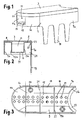
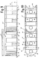
- the in Fig. 1 to 3 The curb as a whole has the shape of an elongate block whose both ends are bounded by circular arcuate curved end walls 5a, 5b, the end wall 5a being used as an edging element convex at one end and the other end wall 5b is concavely curved with the same radius.
- the lower part 1 is as out Fig. 2 can be seen, a thin-walled injection molded part with two parallel side walls 7a, 7b and an upper wall 8, 9, in which an upwardly open channel 11 with side walls 13a, 13b and a bottom wall 15 is formed. In the bottom wall 15, a plurality of drain openings 17 is formed.
- the cover 3 is a flat plate whose shape corresponds to the plan shape of the lower part 1 with concave or convex end faces and which carries at its edge circumferentially a downwardly directed collar 23 which is received and centered by a stepped recess 25 of the lower part.
- a downwardly directed collar 23 which is received and centered by a stepped recess 25 of the lower part.
- the lid projecting pins 27 ( Fig. 4 ), which can snap-snap into corresponding receiving openings 29 of the lower part to hold the lid 3 with a press fit on the lower part 1.
- the clamping seat can also be effected alone by the encircling collar 23.
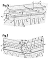
- At the convexly rounded end of the channel 11 has a funnel-shaped widening orifice 11 a, which is bounded by corresponding angled portions 13 c of its side walls 13. (see also Fig. 5 )
- the opening angle of the extension of the channel 11 may be for example 30 °.
- the funnel-shaped extension of the channel 11 makes it possible to maintain the full width of the channel average, even if abutting edge stones are laid at an angle to each other.
- Fig. 5 shows, the lateral areas of the extension 11 a of the channel 11 are closed by thin end wall parts 31 a, 31 b. If two edge stones laid at an angle to each other, so prevents the end wall portion 31 b at the angle outside that the channel 11 is open at this point laterally.
- the thin end wall parts 31 a, 31 b are wegbrechbar.
- the respective end wall part 31a located on the inside of the angle is broken away in order to release the full channel cross section.
- the Kanteristeinunterteil 1 at its concave end a projecting hook-shaped support flange 33 which forms an upwardly open groove.
- a downwardly directed semicircular web 34 is formed.
- the groove formed by the hook-shaped flange 33 receives the web 34 of the respectively adjacent edge stone 1 ', so that the two edging stones are coupled to one another in a tensile-resistant manner.
- the complementary circular arc shape of groove 33 and web 34 allows any bending of the edge stones 1,1 'to each other. If the stones 1 and 1 'laid at an angle to each other, so the end 33' of the hook-shaped flange 33 abut against a step 34 'of the web 34, whereby the maximum angle of rotation between the stones 1 and 1' is set.
- edge bricks With a plurality of edge bricks according to the illustrated embodiment, which are laid in a straight line or at an angle abutting one obtains a lawn or bed enclosure with a continuous channel for receiving an electrical cable and / or irrigation hose and / or any other Management.
- the ducted cable and / or hose may be permanent, i. lie down all year long. It is not necessary to excavate a separate trench for laying the hose or cable.
- the lid 3 By lifting the lid 3, the cable or hose is always accessible. In particular, it is possible to access the end of the hose or cable in a targeted manner by lifting off the respective lid, in order, for example, to access it there. an irrigation sprinkler or an electrical appliance, e.g. to connect an electric lawnmower.
- one or more of the curbs can be equipped with a special lid, which is equipped with a socket for a power connection or for a water connection (not shown in the drawings).
- a socket for a power connection or for a water connection (not shown in the drawings).
- an irrigation sprinkler or an electric lawnmower can be connected without having to open the lid.
- lid 3 transparent and to accommodate in channel 11 a lamp connected to the electrical cable to illuminate the lawn or bed enclosure.
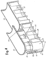
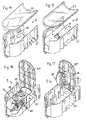
- the 8 to 17 show curbs according to a second embodiment of the invention, one of the embodiment according to Fig. 1 to 7 has different geometry.
- the Fig. 8 . 9 and 10 show two coupled edge stones, each having a lower part 51, 51 'and an upper part or lid 53, 53'.
- the lower part and lid are both concave at one end and convexly rounded at the other end with the same radius.
- the cover 53 has for the snap-fastening on the lower part 51 lateral projections 54 which in recesses 56 (FIG. Fig. 9 ) of the lower part can engage.
- the lower part 51 or 51 ' has a greater height than in the embodiment according to FIG Fig.
- a low-lying floor 65 which defines a lower system level A, on which, for example, a continuous cable or a water hose can be stored.
- End openings 60, 61 in the concave and convex ends of the curbs provide a continuous channel for laying the cable or hose.
- the opening 61 is limited in width by curved, inwardly projecting wall portions 62, to which the vertical edges of the side walls of an angle adjoining element can create a sealing.
- inwardly projecting base 55 On the side walls of the lower part 51 inwardly projecting base 55 are formed, which, starting from the bottom 65, extend over a portion of the clear height of the lower part 51 and form with their upper end support shoulders, which define a second, upper system level B. On these shoulders formed by the sockets 55, installation elements such as a shelf, an electrical junction box or the like can be mounted in the second system level B.
- the Abstützsockeln 55 screw dome 57 are also assigned for receiving self-tapping screws with which the additional elements can be attached.
- anchoring webs 69 for anchoring the edge stone in the ground and breakable wall portions 63 for creating an opening for the lateral insertion of a cable or hose.
- a hook 83 At the convex end is a hook 83, according to Fig. 10 may engage from below into an arcuate slot formed in the bottom of an adjacent edge stone at its concave end.
- adjacent edge stones can be coupled to each other pivotally, wherein the pivoting range can be about 30 ° in both directions.
- Fig. 10 can be seen in the bottom 65 of the lower part 51 and 51 'arcuate slot openings 67 are formed so that they can serve as drainage holes for the flow of water on the one hand and on the other hand define a breakable bottom portion 68, by breaking out an opening for the insertion of a cable or Hose can be created from below.
- the lower openings of the screw domes 57 can be seen for the insertion of fastening screws.
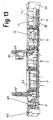
- FIG. 12 shown embodiment of an edge stone differs from the embodiment according to 8 to 11 mainly in that the upper part or the cover 53 is "pivotally mounted on the lower part 51".
- the lid 53 Serve for this purpose laterally projecting bearing pin (not shown) of the lid 53 ", which engage in bearing openings 79 of the lower part 51".
- Each bearing opening 79 is outwardly rounded, so that the lid 53 can be moved downward by a movement corresponding to the arrow 76, behind a locking shoulder 77
- the cover 53 ' can be lifted upwards in accordance with the arrow 76.
- the lower part 51' in accordance with FIG Fig. 12 also includes support pedestals 55 defining an upper system plane and screw domes 57, which in this case are formed separately from the support pedestals 55 are, for receiving fastening screws. Also in the lid 53 "sterdome 87 are formed.
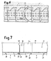
- the Fig. 13 illustrates how edge elements according to Fig. 8 respectively Fig. 12 can be laid in combination with each other to form a continuous lawn or bedding edge, wherein the elements can be equipped with different functions.
- the according to Fig. 13 juxtaposed curb elements are labeled right to left with a, b, c, d, e.
- a convex termination piece 59 At the right end of the series by a convex termination piece 59 and at the left end by a concave end piece 60 is completed.
- Between the end pieces 59, 60 form the juxtaposed elements on its lower or bottom plane a continuous channel for the installation of a water hose 76 (in Fig. 13 schematically indicated by a series of vertical, black bars) and / or an electric cable 78.
- This in Fig. 13 right element a which is also in Fig. 15 has essentially the in Fig. 8 illustrated embodiment, however, has been configured to a lighting element by inserting an intermediate floor 71 which is supported on the Abstützsockel 55 of the lower part 51.
- the intermediate bottom 71 carries an electric lighting element 73 and is designed as a reflector for the same.
- the (in Fig. 13 not shown) cover 53 for the edge element a is designed to be more translucent.
- the second element b in right from the right Fig. 13 also has the in Fig. 8 illustrated shaping of a base element.
- an electrical Verteilerdoses 75 is used in the upper system level and fastened by screws.
- the fourth element d in Fig. 13 is a blank or base element and has the in Fig. 8 as in Fig. 14 illustrated shape.
- the snap-on lid 53 shown in this element d is also in the elements a and b in Fig. 13structzunach.
- FIG. 13 left element e which is also in Fig. 16 is shown again in the Fig. 12
- the support base 55 (FIG. Fig. 12 ) supported and secured by screws 58 and the screw bases 57 intermediate bottom 72, which carries a hose 76 which can be coupled to the water connection 81, such as two coupling nipples 82 for connecting a garden hose and / or a lawn sprinkler.
- the covers 3 and 53 of all elements may have a relief structure on their upper side in order to make them non-slip and / or to mimic the appearance of natural stone together with a suitable coloring.
Landscapes
- Life Sciences & Earth Sciences (AREA)
- Environmental Sciences (AREA)
- Road Paving Structures (AREA)
- Pretreatment Of Seeds And Plants (AREA)
- Cultivation Of Plants (AREA)
Claims (10)
- Elément modulaire destiné à être utilisé comme pierre de lisière pour bordures de pelouses ou de plates-bandes ou dispositifs similaires sous forme d'un bloc allongé qui peut être posé dans la terre à fleur de surface et qui comporte une face supérieure plane accessible, l'élément modulaire (1) comportant à l'une de ses extrémités un arrondi convexe et à l'autre de ses extrémités un congé concave complémentaire de ce dernier de telle sorte que des éléments modulaires adjacents par leurs faces frontales puissent être posés sans interstices selon n'importe quel angle les uns par rapport aux autres,
caractérisé en ce que l'élément modulaire est constitué d'une partie inférieure (1, 51) qui forme un canal (11) continu dans la direction longitudinale et ouvert sur les deux faces latérales et d'un couvercle (3, 53) posé sur la partie inférieure (1, 51),
l'orifice de sortie du canal (11a, 61) étant limité en largeur à l'extrémité en forme de courbure convexe de l'élément modulaire par des parties de mur (31a, 31 b ; 61a, 61b) recourbées faisant saillie vers l'intérieur de telle sorte qu'il se raccorde sans interstices latéraux à l'ouverture du canal à l'extrémité concave d'un élément modulaire adjacent. - Elément modulaire selon la revendication 1, caractérisé en ce que le couvercle (3) est fixé de manière amovible sur la partie inférieure (1) à l'aide d'un raccord encliquetable (27, 29).
- Elément modulaire selon la revendication 1, caractérisé en ce que le couvercle (3") est logé de manière repliable dans la partie inférieure (51).
- Elément modulaire selon la revendication 3, caractérisé en ce que le couvercle (53") peut être bloqué dans la position repliée.
- Elément modulaire selon l'une quelconque des revendications 1 à 4, caractérisé en ce qu'il est prévu au moins une ouverture d'évacuation (17) dans la paroi de fond (15) de la partie inférieure (1).
- Elément modulaire selon l'une quelconque des revendications 1 à 5, caractérisé en ce qu'un élément d'éclairage (73) est placé dans la partie inférieure (1) et en ce que le couvercle est transparent.
- Elément modulaire selon l'une quelconque des revendications 1 à 6, caractérisé en ce qu'un raccord enfichable (81, 82) pour le raccordement d'un tuyau flexible ou une prise de courant électrique (85) est montée dans l'élément modulaire.
- Elément modulaire selon l'une quelconque des revendications 1 à 7, caractérisé en ce qu'il comporte à l'une de ses extrémités une partie en saillie d'accouplement (83) et à l'autre de ses extrémités un logement (84) sous forme de fente et similaire, adapté pour loger une partie en saillie d'accouplement (83) de ce type, de telle sorte que deux éléments modulaires adjacents puissent être couplés l'un à l'autre de manière à résister à la traction par la mise en prise de la partie en saillie d'accouplement (83) et du logement (84), la partie en saillie d'accouplement (83) et le logement (84) étant disposés en forme d'arc de cercle de telle sorte que les éléments de construction peuvent être couplés les uns aux autres selon n'importe quel angle.
- Elément modulaire selon l'une quelconque des revendications 1 à 8, caractérisé en ce qu'il comporte dans la zone inférieure un fond (65) qui forme une surface de pose pour un câble, un tuyau flexible ou un autre dispositif similaire et en ce qu'il est prévu à l'intérieur de la partie inférieure (1) des épaulements d'appui (55) placés à distance du fond (65) sur lesquels des composants encastrés dans l'élément modulaire peuvent s'appuyer.
- Système constitué de plusieurs éléments modulaires selon l'une quelconque des revendications 1 à 9 pour la formation d'une bordure de pelouses ou de plates-bandes, caractérisé en ce que le système comprend des éléments modulaires équipés différemment, à savoir plusieurs éléments modulaires qui forment seulement un canal continu (11) sans composants encastrés et au moins l'un des éléments modulaires suivants :- un élément modulaire avec un appareil d'éclairage encastré (73) et un couvercle transparent ;- un élément modulaire avec une prise de courant électrique (85) ; et/ ou- un élément modulaire avec un raccord de tuyau flexible (81, 82).
Applications Claiming Priority (5)
| Application Number | Priority Date | Filing Date | Title |
|---|---|---|---|
| DE20202732U | 2002-02-21 | ||
| DE20202732U DE20202732U1 (de) | 2002-02-21 | 2002-02-21 | Kantenstein, insbesondere für Rasen- oder Beet-Einfassungen |
| DE20300349U DE20300349U1 (de) | 2003-01-10 | 2003-01-10 | Kantenstein, insbesondere für Rasen- oder Beet-Einfassungen |
| DE20300349U | 2003-01-10 | ||
| PCT/EP2003/001806 WO2003069976A1 (fr) | 2002-02-21 | 2003-02-21 | Element modulaire pour la formation de bordures ou analogues pour pelouses ou plates-bandes |
Publications (2)
| Publication Number | Publication Date |
|---|---|
| EP1476009A1 EP1476009A1 (fr) | 2004-11-17 |
| EP1476009B1 true EP1476009B1 (fr) | 2008-05-14 |
Family
ID=27758647
Family Applications (1)
| Application Number | Title | Priority Date | Filing Date |
|---|---|---|---|
| EP03714752A Expired - Lifetime EP1476009B1 (fr) | 2002-02-21 | 2003-02-21 | Element modulaire pour la formation de bordures ou analogues pour pelouses ou plates-bandes |
Country Status (6)
| Country | Link |
|---|---|
| EP (1) | EP1476009B1 (fr) |
| AT (1) | ATE394918T1 (fr) |
| AU (1) | AU2003218996A1 (fr) |
| CA (1) | CA2476893A1 (fr) |
| DE (1) | DE50309841D1 (fr) |
| WO (1) | WO2003069976A1 (fr) |
Families Citing this family (5)
| Publication number | Priority date | Publication date | Assignee | Title |
|---|---|---|---|---|
| US10203097B2 (en) | 2014-09-08 | 2019-02-12 | Philips Lighting Holding B.V. | Extruded channel plate as basis for integrated functions |
| AT520678A1 (de) * | 2017-09-27 | 2019-06-15 | Jonser Hubert | Einschlagbare einteilige Mähkante |
| US10064348B1 (en) | 2017-10-17 | 2018-09-04 | Orlando Borras | Landscape border system |
| US10448580B1 (en) | 2017-10-17 | 2019-10-22 | Orlando Borras | Landscape border |
| US11028984B2 (en) | 2018-09-07 | 2021-06-08 | Todd Conway | Lighted reinforced landscape structure |
Family Cites Families (7)
| Publication number | Priority date | Publication date | Assignee | Title |
|---|---|---|---|---|
| US3373668A (en) * | 1965-12-15 | 1968-03-19 | Robert R. Moore | Interlocking structures for edging, paving, or the like |
| US4945675A (en) * | 1988-08-23 | 1990-08-07 | Kendrick Glen T | Dividing, watering and lighting system for lawns |
| DE69330209T2 (de) | 1993-09-20 | 2001-11-22 | Robert I. Goldman | Kit für rasen und blumenbeet |
| DE9420128U1 (de) | 1994-12-16 | 1995-02-09 | W. Neudorff Gmbh Kg, 31860 Emmerthal | Bauteil zur Herstellung von Beeteinfassungen und Abgrenzungen in Gärten und Grünanlagen |
| US5535545A (en) | 1995-05-05 | 1996-07-16 | Matz; Warren W. | Lawn and garden edging system |
| WO2000004758A1 (fr) | 1998-07-23 | 2000-02-03 | Bouma, Johanna, Catharina | Perfectionnement apporte a des bordures |
| DE29915545U1 (de) | 1999-09-02 | 1999-11-25 | KANN GmbH Baustoffwerke, 56170 Bendorf | Einfassungsstein zur Bildung einer Rasen- oder Beetkante |
-
2003
- 2003-02-21 EP EP03714752A patent/EP1476009B1/fr not_active Expired - Lifetime
- 2003-02-21 AT AT03714752T patent/ATE394918T1/de not_active IP Right Cessation
- 2003-02-21 DE DE50309841T patent/DE50309841D1/de not_active Expired - Fee Related
- 2003-02-21 WO PCT/EP2003/001806 patent/WO2003069976A1/fr not_active Ceased
- 2003-02-21 AU AU2003218996A patent/AU2003218996A1/en not_active Abandoned
- 2003-02-21 CA CA002476893A patent/CA2476893A1/fr not_active Abandoned
Also Published As
| Publication number | Publication date |
|---|---|
| EP1476009A1 (fr) | 2004-11-17 |
| AU2003218996A1 (en) | 2003-09-09 |
| AU2003218996A8 (en) | 2008-06-12 |
| WO2003069976A8 (fr) | 2008-04-24 |
| WO2003069976A1 (fr) | 2003-08-28 |
| CA2476893A1 (fr) | 2003-08-28 |
| DE50309841D1 (de) | 2008-06-26 |
| ATE394918T1 (de) | 2008-05-15 |
Similar Documents
| Publication | Publication Date | Title |
|---|---|---|
| DE69703456T2 (de) | Modulrinne für Abflusskanäle | |
| EP0224095B1 (fr) | Panneau de treillis en matière synthétique, en particulier en matière synthétique de recyclage | |
| EP2360330B1 (fr) | Connecteur de plinthes | |
| DE69925460T2 (de) | Dacheindeckung für gebäude mit aus kunststoffharz geformten elementen | |
| DE10110568C1 (de) | Kabelbrücke | |
| DE9005078U1 (de) | Rasenbefestigungsplatte | |
| EP1476009B1 (fr) | Element modulaire pour la formation de bordures ou analogues pour pelouses ou plates-bandes | |
| EP0716803B1 (fr) | Elément de construction pour la fabrication de bordures et limites dans les jardins et espaces verts | |
| DE20300349U1 (de) | Kantenstein, insbesondere für Rasen- oder Beet-Einfassungen | |
| DE19524103C2 (de) | Säule | |
| EP0905842B1 (fr) | Poste de distribution d'énergie placé à un endroit semi-publique pour alimenter un particulier ou une entreprise | |
| DE69605764T2 (de) | Endstuck fur ein fuhrungskanal fur elektrische leiter | |
| EP2086078B1 (fr) | Boîtier de distribution destiné à l'intégration dans une ouverture murale | |
| EP1414124B1 (fr) | Canal d'alimentation extérieur pour contenir des canalisations d'eau et/ou d'électricité | |
| DE20202732U1 (de) | Kantenstein, insbesondere für Rasen- oder Beet-Einfassungen | |
| DE102012214334A1 (de) | Beleuchtungsprofil | |
| WO2006042694A1 (fr) | Rigole d'ecoulement des eaux | |
| EP2872712B1 (fr) | Kit de construction destiné à la réalisation de revêtements | |
| DE102005024583B4 (de) | Rasenkantenstein | |
| DE3811307C2 (de) | Verteilerkasten für die Fernmeldetechnik | |
| DE2243133A1 (de) | Anschlussblock fuer den elektrischen anschluss von leuchten und beleuchteten gegenstaenden und aus diesen zusammengestellte anschlusseinheit | |
| EP2904161A1 (fr) | Caniveau à fente | |
| DE202006000797U1 (de) | Anschlussdose für den Anschluss von Datenkabeln | |
| DE20217897U1 (de) | Straßenablauf | |
| DE2328235C3 (de) | Mehrzweckinstallationskanal zur Wandverlegung, insbesondere für die Gebäudeelektroinstallation |
Legal Events
| Date | Code | Title | Description |
|---|---|---|---|
| PUAI | Public reference made under article 153(3) epc to a published international application that has entered the european phase |
Free format text: ORIGINAL CODE: 0009012 |
|
| 17P | Request for examination filed |
Effective date: 20040811 |
|
| AK | Designated contracting states |
Kind code of ref document: A1 Designated state(s): AT BE BG CH CY CZ DE DK EE ES FI FR GB GR HU IE IT LI LU MC NL PT SE SI SK TR |
|
| AX | Request for extension of the european patent |
Extension state: AL LT LV MK RO |
|
| GRAP | Despatch of communication of intention to grant a patent |
Free format text: ORIGINAL CODE: EPIDOSNIGR1 |
|
| GRAS | Grant fee paid |
Free format text: ORIGINAL CODE: EPIDOSNIGR3 |
|
| GRAA | (expected) grant |
Free format text: ORIGINAL CODE: 0009210 |
|
| AK | Designated contracting states |
Kind code of ref document: B1 Designated state(s): AT BE BG CH CY CZ DE DK EE ES FI FR GB GR HU IE IT LI LU MC NL PT SE SI SK TR |
|
| AX | Request for extension of the european patent |
Extension state: AL LT LV RO |
|
| REG | Reference to a national code |
Ref country code: GB Ref legal event code: FG4D Free format text: NOT ENGLISH |
|
| REG | Reference to a national code |
Ref country code: CH Ref legal event code: EP |
|
| REG | Reference to a national code |
Ref country code: IE Ref legal event code: FG4D Free format text: LANGUAGE OF EP DOCUMENT: GERMAN |
|
| REG | Reference to a national code |
Ref country code: CH Ref legal event code: NV Representative=s name: TROESCH SCHEIDEGGER WERNER AG |
|
| REF | Corresponds to: |
Ref document number: 50309841 Country of ref document: DE Date of ref document: 20080626 Kind code of ref document: P |
|
| PG25 | Lapsed in a contracting state [announced via postgrant information from national office to epo] |
Ref country code: SI Free format text: LAPSE BECAUSE OF FAILURE TO SUBMIT A TRANSLATION OF THE DESCRIPTION OR TO PAY THE FEE WITHIN THE PRESCRIBED TIME-LIMIT Effective date: 20080514 |
|
| PG25 | Lapsed in a contracting state [announced via postgrant information from national office to epo] |
Ref country code: FI Free format text: LAPSE BECAUSE OF FAILURE TO SUBMIT A TRANSLATION OF THE DESCRIPTION OR TO PAY THE FEE WITHIN THE PRESCRIBED TIME-LIMIT Effective date: 20080514 Ref country code: ES Free format text: LAPSE BECAUSE OF FAILURE TO SUBMIT A TRANSLATION OF THE DESCRIPTION OR TO PAY THE FEE WITHIN THE PRESCRIBED TIME-LIMIT Effective date: 20080825 |
|
| NLV1 | Nl: lapsed or annulled due to failure to fulfill the requirements of art. 29p and 29m of the patents act | ||
| PG25 | Lapsed in a contracting state [announced via postgrant information from national office to epo] |
Ref country code: NL Free format text: LAPSE BECAUSE OF FAILURE TO SUBMIT A TRANSLATION OF THE DESCRIPTION OR TO PAY THE FEE WITHIN THE PRESCRIBED TIME-LIMIT Effective date: 20080514 |
|
| REG | Reference to a national code |
Ref country code: IE Ref legal event code: FD4D |
|
| PG25 | Lapsed in a contracting state [announced via postgrant information from national office to epo] |
Ref country code: CZ Free format text: LAPSE BECAUSE OF FAILURE TO SUBMIT A TRANSLATION OF THE DESCRIPTION OR TO PAY THE FEE WITHIN THE PRESCRIBED TIME-LIMIT Effective date: 20080514 Ref country code: IE Free format text: LAPSE BECAUSE OF FAILURE TO SUBMIT A TRANSLATION OF THE DESCRIPTION OR TO PAY THE FEE WITHIN THE PRESCRIBED TIME-LIMIT Effective date: 20080514 Ref country code: DK Free format text: LAPSE BECAUSE OF FAILURE TO SUBMIT A TRANSLATION OF THE DESCRIPTION OR TO PAY THE FEE WITHIN THE PRESCRIBED TIME-LIMIT Effective date: 20080514 Ref country code: SE Free format text: LAPSE BECAUSE OF FAILURE TO SUBMIT A TRANSLATION OF THE DESCRIPTION OR TO PAY THE FEE WITHIN THE PRESCRIBED TIME-LIMIT Effective date: 20080814 Ref country code: PT Free format text: LAPSE BECAUSE OF FAILURE TO SUBMIT A TRANSLATION OF THE DESCRIPTION OR TO PAY THE FEE WITHIN THE PRESCRIBED TIME-LIMIT Effective date: 20081014 |
|
| PG25 | Lapsed in a contracting state [announced via postgrant information from national office to epo] |
Ref country code: SK Free format text: LAPSE BECAUSE OF FAILURE TO SUBMIT A TRANSLATION OF THE DESCRIPTION OR TO PAY THE FEE WITHIN THE PRESCRIBED TIME-LIMIT Effective date: 20080514 |
|
| PLBE | No opposition filed within time limit |
Free format text: ORIGINAL CODE: 0009261 |
|
| STAA | Information on the status of an ep patent application or granted ep patent |
Free format text: STATUS: NO OPPOSITION FILED WITHIN TIME LIMIT |
|
| 26N | No opposition filed |
Effective date: 20090217 |
|
| PG25 | Lapsed in a contracting state [announced via postgrant information from national office to epo] |
Ref country code: BG Free format text: LAPSE BECAUSE OF FAILURE TO SUBMIT A TRANSLATION OF THE DESCRIPTION OR TO PAY THE FEE WITHIN THE PRESCRIBED TIME-LIMIT Effective date: 20080814 Ref country code: EE Free format text: LAPSE BECAUSE OF FAILURE TO SUBMIT A TRANSLATION OF THE DESCRIPTION OR TO PAY THE FEE WITHIN THE PRESCRIBED TIME-LIMIT Effective date: 20080514 |
|
| PGFP | Annual fee paid to national office [announced via postgrant information from national office to epo] |
Ref country code: AT Payment date: 20090219 Year of fee payment: 7 |
|
| PGFP | Annual fee paid to national office [announced via postgrant information from national office to epo] |
Ref country code: CH Payment date: 20090223 Year of fee payment: 7 Ref country code: GB Payment date: 20090223 Year of fee payment: 7 |
|
| BERE | Be: lapsed |
Owner name: MARLEY DEUTSCHLAND G.M.B.H. Effective date: 20090228 |
|
| PG25 | Lapsed in a contracting state [announced via postgrant information from national office to epo] |
Ref country code: IT Free format text: LAPSE BECAUSE OF FAILURE TO SUBMIT A TRANSLATION OF THE DESCRIPTION OR TO PAY THE FEE WITHIN THE PRESCRIBED TIME-LIMIT Effective date: 20080514 |
|
| PGFP | Annual fee paid to national office [announced via postgrant information from national office to epo] |
Ref country code: DE Payment date: 20090422 Year of fee payment: 7 |
|
| PG25 | Lapsed in a contracting state [announced via postgrant information from national office to epo] |
Ref country code: MC Free format text: LAPSE BECAUSE OF NON-PAYMENT OF DUE FEES Effective date: 20090228 |
|
| PGFP | Annual fee paid to national office [announced via postgrant information from national office to epo] |
Ref country code: FR Payment date: 20090217 Year of fee payment: 7 |
|
| PG25 | Lapsed in a contracting state [announced via postgrant information from national office to epo] |
Ref country code: BE Free format text: LAPSE BECAUSE OF NON-PAYMENT OF DUE FEES Effective date: 20090228 |
|
| REG | Reference to a national code |
Ref country code: CH Ref legal event code: PL |
|
| GBPC | Gb: european patent ceased through non-payment of renewal fee |
Effective date: 20100221 |
|
| PG25 | Lapsed in a contracting state [announced via postgrant information from national office to epo] |
Ref country code: LI Free format text: LAPSE BECAUSE OF NON-PAYMENT OF DUE FEES Effective date: 20100228 Ref country code: GR Free format text: LAPSE BECAUSE OF FAILURE TO SUBMIT A TRANSLATION OF THE DESCRIPTION OR TO PAY THE FEE WITHIN THE PRESCRIBED TIME-LIMIT Effective date: 20080815 Ref country code: CH Free format text: LAPSE BECAUSE OF NON-PAYMENT OF DUE FEES Effective date: 20100228 |
|
| REG | Reference to a national code |
Ref country code: FR Ref legal event code: ST Effective date: 20101029 |
|
| PG25 | Lapsed in a contracting state [announced via postgrant information from national office to epo] |
Ref country code: AT Free format text: LAPSE BECAUSE OF NON-PAYMENT OF DUE FEES Effective date: 20100221 |
|
| PG25 | Lapsed in a contracting state [announced via postgrant information from national office to epo] |
Ref country code: FR Free format text: LAPSE BECAUSE OF NON-PAYMENT OF DUE FEES Effective date: 20100301 |
|
| PG25 | Lapsed in a contracting state [announced via postgrant information from national office to epo] |
Ref country code: DE Free format text: LAPSE BECAUSE OF NON-PAYMENT OF DUE FEES Effective date: 20100901 |
|
| PG25 | Lapsed in a contracting state [announced via postgrant information from national office to epo] |
Ref country code: GB Free format text: LAPSE BECAUSE OF NON-PAYMENT OF DUE FEES Effective date: 20100221 |
|
| PG25 | Lapsed in a contracting state [announced via postgrant information from national office to epo] |
Ref country code: LU Free format text: LAPSE BECAUSE OF NON-PAYMENT OF DUE FEES Effective date: 20090221 |
|
| PG25 | Lapsed in a contracting state [announced via postgrant information from national office to epo] |
Ref country code: HU Free format text: LAPSE BECAUSE OF FAILURE TO SUBMIT A TRANSLATION OF THE DESCRIPTION OR TO PAY THE FEE WITHIN THE PRESCRIBED TIME-LIMIT Effective date: 20081115 |
|
| PG25 | Lapsed in a contracting state [announced via postgrant information from national office to epo] |
Ref country code: TR Free format text: LAPSE BECAUSE OF FAILURE TO SUBMIT A TRANSLATION OF THE DESCRIPTION OR TO PAY THE FEE WITHIN THE PRESCRIBED TIME-LIMIT Effective date: 20080514 |
|
| PG25 | Lapsed in a contracting state [announced via postgrant information from national office to epo] |
Ref country code: CY Free format text: LAPSE BECAUSE OF FAILURE TO SUBMIT A TRANSLATION OF THE DESCRIPTION OR TO PAY THE FEE WITHIN THE PRESCRIBED TIME-LIMIT Effective date: 20080514 |