EP1476292B1 - Ensemble entree pouvant reduire la coulure d'une matiere fondue provenant d'une tige de coulee - Google Patents
Ensemble entree pouvant reduire la coulure d'une matiere fondue provenant d'une tige de coulee Download PDFInfo
- Publication number
- EP1476292B1 EP1476292B1 EP03704121A EP03704121A EP1476292B1 EP 1476292 B1 EP1476292 B1 EP 1476292B1 EP 03704121 A EP03704121 A EP 03704121A EP 03704121 A EP03704121 A EP 03704121A EP 1476292 B1 EP1476292 B1 EP 1476292B1
- Authority
- EP
- European Patent Office
- Prior art keywords
- sprue
- gate assembly
- channel
- melt
- injection molding
- Prior art date
- Legal status (The legal status is an assumption and is not a legal conclusion. Google has not performed a legal analysis and makes no representation as to the accuracy of the status listed.)
- Expired - Lifetime
Links
- 206010013642 Drooling Diseases 0.000 title description 6
- 208000008630 Sialorrhea Diseases 0.000 title description 6
- 239000000155 melt Substances 0.000 claims description 68
- 238000001746 injection moulding Methods 0.000 claims description 43
- 239000000463 material Substances 0.000 claims description 5
- 238000004891 communication Methods 0.000 claims description 3
- 230000000712 assembly Effects 0.000 description 7
- 238000000429 assembly Methods 0.000 description 7
- 238000000465 moulding Methods 0.000 description 6
- 230000013011 mating Effects 0.000 description 3
- 230000007246 mechanism Effects 0.000 description 3
- 230000008901 benefit Effects 0.000 description 2
- 238000001816 cooling Methods 0.000 description 2
- 230000009471 action Effects 0.000 description 1
- 230000008878 coupling Effects 0.000 description 1
- 238000010168 coupling process Methods 0.000 description 1
- 238000005859 coupling reaction Methods 0.000 description 1
- 230000007423 decrease Effects 0.000 description 1
- 230000003247 decreasing effect Effects 0.000 description 1
- 230000001419 dependent effect Effects 0.000 description 1
- 238000002347 injection Methods 0.000 description 1
- 239000007924 injection Substances 0.000 description 1
- 230000003993 interaction Effects 0.000 description 1
- 238000004519 manufacturing process Methods 0.000 description 1
- 238000012986 modification Methods 0.000 description 1
- 230000004048 modification Effects 0.000 description 1
- 239000012768 molten material Substances 0.000 description 1
- 238000000926 separation method Methods 0.000 description 1
- 238000011144 upstream manufacturing Methods 0.000 description 1
Images


Classifications
-
- F—MECHANICAL ENGINEERING; LIGHTING; HEATING; WEAPONS; BLASTING
- F16—ENGINEERING ELEMENTS AND UNITS; GENERAL MEASURES FOR PRODUCING AND MAINTAINING EFFECTIVE FUNCTIONING OF MACHINES OR INSTALLATIONS; THERMAL INSULATION IN GENERAL
- F16L—PIPES; JOINTS OR FITTINGS FOR PIPES; SUPPORTS FOR PIPES, CABLES OR PROTECTIVE TUBING; MEANS FOR THERMAL INSULATION IN GENERAL
- F16L29/00—Joints with fluid cut-off means
- F16L29/04—Joints with fluid cut-off means with a cut-off device in each of the two pipe ends, the cut-off devices being automatically opened when the coupling is applied
-
- B—PERFORMING OPERATIONS; TRANSPORTING
- B29—WORKING OF PLASTICS; WORKING OF SUBSTANCES IN A PLASTIC STATE IN GENERAL
- B29C—SHAPING OR JOINING OF PLASTICS; SHAPING OF MATERIAL IN A PLASTIC STATE, NOT OTHERWISE PROVIDED FOR; AFTER-TREATMENT OF THE SHAPED PRODUCTS, e.g. REPAIRING
- B29C45/00—Injection moulding, i.e. forcing the required volume of moulding material through a nozzle into a closed mould; Apparatus therefor
- B29C45/17—Component parts, details or accessories; Auxiliary operations
- B29C45/26—Moulds
- B29C45/32—Moulds having several axially spaced mould cavities, i.e. for making several separated articles
- B29C45/322—Runner systems for distributing the moulding material to the stacked mould cavities
Definitions
- the present invention relates generally to an injection molding apparatus and, in particular, to a gate assembly for reducing drooling of melt from a sprue bar.
- WO-A-01/14118 describes a melt transfer system for a stack mold.
- the melt transfer system comprises a first sprue bar element having a first sprue channel for receiving a melt stream of a moldable material and a second sprue bar element having a second sprue channel for selectively receiving the melt stream from the first sprue cahnnel.
- a manifold is disclosed having a manifold channel for receiving the melt stream from the second sprue channel and delivering the melt stream to a nozzle channel of a nozzle.
- the melt stream is submitted to a mold cavity, wherein the nozzle channel is in communication with the mold cavity through a mold gate.
- Stack molding provides an advantage over single molding in that it enables the output of an injection molding machine to be at least doubled without significantly increasing its size.
- Stack mold configurations generally employ a stationary first platen, a movable center platen and a movable second platen.
- the mold cavities are conventionally located on opposing faces of the movable center platen.
- the movable center platen and the second movable platen reciprocate to open and close the mold cavities during a production cycle.
- the melt runner system or the manifold system extends through the center platen in order to reach the mold cavities located on each side of the center platen via an equal path length.
- multi-cavity stack molds use a single and movable sprue bar to provide a direct melt channel between the extruder nozzle of the injection molding machine and its hot runner distributor, or manifold, which is mounted in the center section of the stack mold.
- the manifold delivers melt from the sprue bar into injection nozzles that are associated with each individual mold cavity.
- the sprue bar is continuously coupled to and decoupled from the melt source. It is therefore necessary to control the flow of the pressurized melt stream when the sprue bar is decoupled from the melt source so that substantially no drooling occurs.
- a valve gated stack injection molding apparatus such as disclosed in U.S. Patent No. 5,460,510, controls the flow of melt between platens using valve pin members located in the melt channel.
- the upstream and downstream nozzles each have valve pins that reciprocate between retracted open positions and closed positions in which the valve pins are seated in respective gates.
- This valve pin arrangement has several disadvantages.
- the volume of melt that can be transferred through the nozzles is decreased and the pressure in the nozzles is increased because the valve pins are located and move inside the melt channel. Further, the melt experiences additional shear stress as it travels around the valve pins and through the nozzles, which causes flow lines in a molded part.
- a thermal gated melt transfer system such as disclosed in U.S. Patent No. 4,891,001, controls the flow of melt between platens using a combination of heated nozzles.
- a disadvantage of thermal gated melt transfer systems is that the flow of pressurized melt is impeded by the relatively small diameter gate defined in each heated nozzle. Stack molds require the transfer of a large amount of melt, which warrants a larger diameter nozzle gate. If the nozzle gate diameter is increased, the melt stream cannot effectively be frozen and therefore, drooling and stringing of molten material occurs. Furthermore, there is a delay associated with cooling and remelting of the melt in the nozzle gate for each molding cycle.
- U.S. Patent No. 5,044,927 discloses a disengageable link between a movable machine nozzle and a sprue bar. The '927 patent does not include an anti-drooling mechanism.
- An improved stack mold melt transfer system is particularly needed for large scale molding operations involving large volumes of melt being transferred at one time.
- an injection molding apparatus comprising: a first sprue bar element having a first sprue channel for receiving a melt stream of moldable material under pressure; a second sprue bar element having a second sprue channel for selectively receiving the melt stream from the first sprue channel; a manifold having a manifold channel for receiving the melt stream from the second sprue channel and delivering the melt stream to a nozzle channel of a nozzle; a mold cavity receiving the melt stream from the nozzle, the nozzle channel communicating with the mold cavity through a mold gate; a first gate assembly coupled to an outlet of the first sprue bar element for selectively restricting the flow of the melt stream from the first sprue channel; a second gate assembly coupled to an inlet of the second sprue bar element for selectively restricting the flow of the melt stream from the second sprue channel; and wherein the first gate assembly and the second gate assembly are movable to restrict the flow of melt from the first s
- the present invention provides advantages in that drool is reduced inside a stack injection molding machine without disrupting the flow of melt inside the channel.
- a stack injection molding apparatus is generally indicated by reference numeral 10.
- a base 20 supports a stationary first platen 14, a movable center platen 16 and a movable second platen 18.
- the movable center platen 16 and movable second platen 18 are coupled to the stationary first platen 14 and are movable relative thereto, as indicated by arrows 22 and 24, by a positioning mechanism (not shown).
- the movable center platen 16 and the movable second platen 18 split the stack injection molding apparatus 10 at parting lines 26 and 28, respectively.
- a first series of mold cavities 30 is located between the movable center platen 16 and a first series of mold cores 31, which project from the stationary first platen 14.
- a second series of mold cavities 32 is located between the movable center platen 16 and a second series of mold cores 33, which project from the movable second platen 18.
- a sprue bar 34 extends between a machine nozzle 12 and a manifold 50, which is located in movable center platen 16.
- the sprue bar 34 comprises a first sprue bar element 36, having a first passage 37, selectively coupled to a second sprue bar element 38, having a second passage 39, through a melt transfer device 40.
- the first sprue bar element 36 is coupled to the second sprue bar element 38 by the melt transfer device to allow melt to flow therebetween.
- the machine nozzle 12 receives a melt stream of moldable material from a hopper 13 and delivers the melt stream under pressure through the sprue bar 34 to a manifold 50.
- the manifold 50 distributes the melt stream to a series of nozzles 44.
- the melt stream flows through the nozzles 44, past mold gates 46 and into mold cavities 30, 32, where the melt cools to produce molded parts (not shown).
- the movable center platen 16 and the movable second platen 18 separate from the stationary first platen 14, at parting lines 26 and 28, respectively, and move into a melt interrupted position, shown in Figure 2. In this position, the flow of melt from the machine nozzle 12 is halted and the molded parts are released from the mold cavities 30, 32.
- FIG. 3 and 4 a stack injection molding apparatus 100 similar to that disclosed in International PCT Application No. WO 01/14118 is shown.
- the stack injection molding apparatus 100 operates in a similar manner to the stack injection molding apparatus 10 of Figures 1 and 2.
- the stack injection molding apparatus 100 includes a stationary first platen 114 having an inlet 112 for coupling to a machine nozzle (not shown) and receiving a melt stream therefrom.
- a movable center platen 116 and a movable second platen 118 are coupled to the stationary first platen 114 and are movable relative thereto, by a positioning mechanism (not shown).
- the movable center platen 116 is separable from the stationary platen 114 at parting line 126 and the movable second platen 118 is separable from the movable center platen 116 at parting line 128.
- a first series of mold cavities 130 is located between a first series of mold cores 131, that project from the stationary platen 114, and the movable center platen 116.
- a second series of mold cavities 132 is located between a second series of mold cores 133, which project from the movable center platen 116, and the movable second platen 118.
- a sprue bar 134 delivers a melt stream of moldable material under pressure from the machine nozzle to a manifold 150.
- the sprue bar 134 includes a first sprue bar element 136, having a first passage 154, selectively coupled to a second sprue bar element 138, having a second passage 156, through a melt transfer device 140.
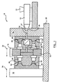
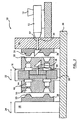
- the melt transfer device 140 is better illustrated in Figures 5 and 6. As can be seen, the melt transfer device 140 includes a first sprue bushing 160, which is coupled to an outlet end the first sprue bar element 136, and a second sprue bushing 162, which is coupled to an inlet end of the second sprue bar element 138.
- the first sprue bushing 160 and the second sprue bushing 162 are selectively coupled to one another though a shear gate.
- First and second locking and support elements 300, 302 are located adjacent the sprue bushings 160, 162.
- the first locking and support element 300 has a slanted surface 304 that forces the second sprue bushing 162 toward the first sprue bushing 160 as the first and second sprue bushings 160, 162 move toward each other.
- the second locking and support element 302 has a slanted surface 306 for forcing the first sprue bushing 160 toward the second sprue bushing 162 as the first and second sprue bushings 160, 162 move toward each other.
- Each sprue bushing 160, 162 includes a head 164, a stem 166 and a generally hook shaped bushing channel 168, which extends through the length thereof
- the straight portions 169 of the bushing channels 168 of the first and second sprue bushings 160, 162 share a common axis. Melt is transferred between an outlet 170 of the first sprue bushing 160 and an inlet 172 of the second sprue bushing 162, when the stack injection molding apparatus 100 is in the melt delivery position of Figure 6.
- a first gate assembly 180 is coupled to a first shoulder 174 of the first sprue bushing 160.
- the first gate assembly 180 includes a cover plate 184 that is coupled to a post 186 and is movable to cover the outlet 170 of the first sprue bushing 160 as indicated by arrow 181.
- a second gate assembly 182 is coupled to a second shoulder 176 of the second sprue bushing 162.
- the second gate assembly 182 also includes a cover plate 184 that is movable to cover the inlet 172 of the second sprue bushing 162, as indicated by arrow 183.
- the first and second gate assemblies 180, 182 are movable between a closed position, which corresponds to the melt interrupted position of Figures 4 and 5, and an open position, which corresponds to the melt delivery position of Figure 3 and 6.
- gate assembly 180 is generally identical to gate assembly 182.
- a recess 178 is formed in each shoulder 174, 176 of the first and second sprue bushings 160, 162.
- An insert 188 is fitted inside the recess 178 and a spring 190 is fixed to an inner wall 192 thereof.
- the spring 190 may be fixed to a bottom surface 194 of the insert 188.
- the post 186 is received within the insert 188 and is coupled to the spring 190.
- the spring 190 biases the post 186 toward the melt interrupted position, shown in Figures 4, 5 and 7.
- the cover plate 184 of the first gate assembly 180 covers the inlet 172 of the second sprue bushing 162.
- the cover plate 184 of the second gate assembly 182 covers the outlet 170 of the first sprue bushing 160. In this arrangement, the flow of melt is restricted from both of the sprue bushings 160, 162 simultaneously.
- Each sprue bushing 160, 162 further includes a projection 196 that extends outwardly from an outer surface 194 thereof.
- Each projection 196 is sized to fit into a groove 198 that is formed in a mating surface 200 of each cover plate 184. The interaction of the projections 196 and grooves 198 ensures that the posts 186 of the gate assemblies 180, 182 move axially in order to maintain the cover plates 184 in shear contact with the inlet 172 and outlet 170.
- the first and second sprue bushings 160 and 162 abut when the stack injection molding apparatus 100 is in the melt delivery position.
- the channels 168 of the first and second sprue bushings 160, 162 are in communication with one another in order to provide a path for the melt stream to flow from the machine nozzle to the mold cavities 130, 132.
- the gate assemblies 180, 182 are held in the open position, in which the springs 190 are compressed and the cover plates 184 are retracted, by the interlocking sprue bushings 160, 162.
- the manifold 150 receives the melt stream from the sprue bar 34 and delivers the melt stream through a series of manifold channels 152 to a series of nozzles 144.
- the melt stream flows through a nozzle channel 148 of each nozzle, past a mold gate 146, and into respective mold cavities 130, 132, where molded parts are formed.
- the pressurized flow of melt from the machine nozzle 12 is halted.
- the first and second movable platens 116, 118 move axially out of contact with the stationary platen 114 and each other as shown in Figures 4 and 5.
- the first and second sprue bar elements 136, 138 are separated so that a space forms between the first sprue bushing 160 and the second sprue bushing 162.
- the separation of the first and second sprue bushings 160, 162 causes the outlet 170 and inlet 172 to shear against one another. This breaks the flow of melt between the outlet 170 and the inlet 172 so that a string of melt does not extend between the separated sprue bushings 160, 162.
- the springs 190 of the gate assemblies 180, 182 extend and force the posts 186 away from the shoulders 174, 176.
- the cover plates 184 abut the inlet 170 and outlet 172 of the first and second sprue bushings 160, 162, thus restricting melt flow therefrom.
- the grooves 198 in the mating surfaces 200 of the cover plates 184 continue to abut the outer surfaces 194 of the opposing sprue bushings 160, 162 until the sprue bushings 160, 162 move out of contact with one another.
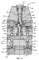
- a further embodiment of a melt transfer device 240 for a stack injection molding apparatus is shown.
- the springs 190 of the embodiment of Figures 5-7 are replaced by pistons 202.
- Seals 204 are provided between each piston 202 and a corresponding cylinder 206.
- Gate assemblies 280 and 282 each include a rod 186 that extends from the piston 202 and a cover plate 184 that moves into and out of engagement with an outlet 270 of a first sprue channel 208 and an inlet 272 of a second sprue channel 210.
- the cylinders 206 contain a constant volume of air.
- the gate assemblies 180, 182 may alternatively be actuated in a manner that does not rely upon the movement of the sprue bushings 160, 162.
- a pneumatic piston may be coupled to the shoulder 174, 176 to move the cover assembly 180, 182 into and out of abutment with the respective inlet 172 or outlet 170.
- the pneumatic piston would operate in conjunction with an external air source.
- the cycle time of a stack injection molding apparatus may be reduced by more than 50% by employing a gate assembly, as described, because the time required to sufficiently cool the melt in a thermal gate is substantially eliminated.
Landscapes
- Engineering & Computer Science (AREA)
- General Engineering & Computer Science (AREA)
- Mechanical Engineering (AREA)
- Manufacturing & Machinery (AREA)
- Moulds For Moulding Plastics Or The Like (AREA)
- Injection Moulding Of Plastics Or The Like (AREA)
Claims (19)
- Un appareil de moulage par injection (100), comprenant :un premier élément à barre de coulée (136), comprenant un premier canal de coulée (154) pour recevoir un flux de masse fondue d'un matériau moulable sous pression ;un deuxième élément à barre de coulée (138), comprenant un deuxième canal de coulée (156) pour recevoir sélectivement ledit flux de masse fondue provenant dudit premier canal de coulée (154) ;un distributeur (150), comprenant un canal de distributeur pour recevoir ledit flux de masse fondue provenant dudit deuxième canal de coulée et pour délivrer le flux de masse fondue à un canal à buse d'une buse ;une cavité de moule (130, 132) recevant ledit flux de masse fondue venant de ladite buse, ledit canal à buse communiquant avec ladite cavité de moule par une plaque de moule ;caractérisé en ce que ledit appareil de moulage par injection comprend en outre :un premier ensemble de porte (180) couplé à une sortie (170) dudit premier élément de barre de coulée (136) pour sélectivement restreindre l'écoulement dudit flux de masse fondue venant dudit premier canal de coulée (154) ;un deuxième élément de porte (182) couplé à une entrée (172) dudit deuxième élément de barre de coulée (138) pour sélectivement restreindre le flux dudit écoulement de masse fondue provenant dudit deuxième canal de coulée (156) ; etdans lequel ledit premier ensemble de porte (180) et ledit deuxième ensemble de porte (182) sont déplaçables pour restreindre le flux de masse fondue venant dudit premier canal de coulée (154) et dudit deuxième canal de coulée (156) lorsque le flux dudit écoulement de masse fondue entre ledit premier canal de coulée (154) et ledit deuxième canal de coulée (156) est interrompu.
- L'appareil de moulage par injection (100) selon la revendication 1, dans lequel ledit premier ensemble de porte (180) est situé à l'extérieur dudit premier canal de coulée (154), et ledit deuxième ensemble de porte (182) est situé à l'extérieur dudit deuxième canal de coulée (156).
- L'appareil de moulage par injection (100) selon la revendication 1, dans lequel ledit premier élément de barre de coulée (136) et ledit deuxième élément de barre de coulée (138) sont déplaçables axialement l'un par rapport à l'autre, entre une première position, à laquelle ladite sortie (170) dudit premier élément de barre de coulée (136) est en communication avec l'entrée (172) dudit deuxième élément de barre de coulée (138), et ledit premier ensemble de porte (180) et ledit deuxième ensemble de porte (182) sont en position ouverte pour permettre un écoulement, entre ladite première barre de coulée (134) et ladite deuxième barre de coulée (136), et une deuxième position, à laquelle ledit premier élément de barre de coulée (136) et ledit deuxième élément de barre de coulée (138) sont séparés axialement l'un de l'autre, et ledit premier ensemble de porte (180) et ledit deuxième ensemble de porte (182) sont en une position fermée, pour limiter l'écoulement de la masse fondue dudit premier canal de coulée (154) et dudit deuxième canal de coulée (156).
- L'appareil de moulage par injection (100) selon la revendication 3, dans lequel ledit premier élément de barre de coulée (136) délivre ledit flux de masse fondue à ladite deuxième barre de coulée, par une porte à cisaillement.
- L'appareil de moulage par injection (100) selon la revendication 4, dans lequel ledit premier ensemble de porte (180) est sollicité pour restreindre l'écoulement venant de ladite sortie (170), et ledit deuxième ensemble de barre (182) est sollicité pour restreindre l'écoulement venant de ladite entrée (172).
- L'appareil de moulage par injection (100) selon la revendication 5, dans lequel ledit premier ensemble de porte (180) et ledit deuxième ensemble de porte (182) sont déplaçables en réponse au déplacement relatif entre ladite première barre de coulée et ladite deuxième barre de coulée.
- La machine de moulage par injection (100) selon la revendication 6, dans laquelle ledit premier ensemble de porte (180) et ledit deuxième ensemble de barre (182) sont déplaçables entre ladite position d'ouverture et ladite position de fermeture, simultanément.
- L'appareil de moulage par injection (100) selon la revendication 4, dans lequel ledit premier canal de coulée (154) et ledit deuxième canal de coulée (156) partagent un axe commun, ladite porte de cisaillement étant alignée avec ledit axe commun.
- L'appareil de moulage par injection (100) selon la revendication 8, comprenant en outre un épaulement (174) faisant saillie depuis ledit premier canal de coulée (156), de façon adjacente à ladite sortie (170), ledit premier ensemble de porte (180) étant monté sur ledit épaulement (174).
- L'appareil de moulage par injection selon la revendication 9, dans lequel ledit premier ensemble de porte (180) comprend une plaque de couvercle (184) qui est montée sur un pilier (186), ledit pilier (186) étant monté dans une cavité formée dans ledit épaulement (174), ledit pilier (186) interagissant avec un dispositif de sollicitation placé dans ladite cavité, pour déplacer ledit premier ensemble de porte (180) de ladite position d'ouverture à ladite position de fermeture.
- L'appareil de moulage par injection selon la revendication 10, dans lequel ladite plaque de couvercle (184) est déplaçable axialement vers ladite position d'ouverture, en réponse à une force axiale appliquée par une surface d'extrémité dudit deuxième élément de barre de coulée (138).
- L'appareil de moulage par injection selon la revendication 11, dans lequel ledit deuxième ensemble de porte (182) est globalement identique audit premier ensemble de porte (180), ledit deuxième ensemble de porte (182) étant déplaçable axialement vers ladite position d'ouverture, en réponse à une force axiale, appliquée par une surface d'extrémité sur ledit premier élément de barre de coulée (136).
- L'appareil de moulage par injection (100) selon l'une des revendications 1 à 12, dans lequel :l'ensemble de porte est couplé à un dispositif de transfert de masse fondue (140) placé le long de la longueur de ladite barre de coulée, ledit dispositif de transfert de masse fondue devant fournir sélectivement un chemin pour ledit flux de masse fondue, afin qu'il s'écoule entre une première partie de ladite barre de coulée et une deuxième partie de ladite barre de coulée, ledit dispositif de transfert de masse fondue étant déplaçable pour interrompre ledit chemin.
- L'appareil de moulage par injection (100) selon la revendication 13, dans lequel le déplacement dudit dispositif de transfert de masse fondue (140) provoque la restriction de l'écoulement dudit flux de masse fondue par ledit ensemble de porte.
- Un appareil de moulage par injection (100) selon les revendications 1, 2 et 3.
- Un appareil de moulage par injection (100) selon la revendication 15,
dans lequel ledit premier ensemble de porte et ledit deuxième ensemble de porte coopèrent pour commander l'écoulement de masse fondue venant dudit premier canal de coulée et dudit deuxième canal de coulée. - Un appareil de moulage par injection (100) selon la revendication 16, dans lequel ladite deuxième position dudit premier ensemble de porte (180) et ladite deuxième position dudit deuxième ensemble de porte (182) empêchent l'écoulement de masse fondue depuis ledit premier canal de coulée et ledit deuxième canal de coulée.
- Un appareil de moulage par injection (100) selon la revendication 3, dans lequel ledit premier ensemble de porte (180) et ledit deuxième ensemble de porte (182) sont actionnés par le déplacement dudit deuxième élément de barre de coulée (136) mobile, de ladite position de fourniture de masse fondue à ladite position d'interruption de la fourniture de masse fondue.
- Un appareil de moulage par injection selon l'une des revendications 1 à 18, comprenant en outre :un plateau (14) stationnaire ;un premier plateau (16) mobile, couplé audit plateau (14) stationnaire et déplaçable en prise et hors de prise avec ledit plateau (14) stationnaire ;un deuxième plateau (18) mobile, couplé audit plateau (14) stationnaire et déplaçable pour venir en prise et hors de prise avec ledit premier plateau (16) mobile ;ledit distributeur (150) étant couplé audit premier plateau (16) mobile et ayant un canal de distributeur pour recevoir ledit flux de masse fondue venant dudit deuxième canal de coulée et délivrant ledit flux de masse fondue à un premier canal à buse d'une première buse et à un deuxième canal à buse d'une deuxième buse ;une première cavité de moule, prévue entre ledit plateau stationnaire et ledit premier plateau mobile, ladite première cavité de moule recevant ledit flux de masse fondue venant dudit premier canal à buse et passant par une première porte de moule ;une deuxième cavité de moule, prévue entre ledit premier plateau (16) mobile et ledit deuxième plateau (18) mobile, ladite deuxième cavité de moule recevant ledit flux de masse fondue venant dudit deuxième canal à buse et passant par une deuxième porte de moule.
Applications Claiming Priority (3)
| Application Number | Priority Date | Filing Date | Title |
|---|---|---|---|
| US76656 | 2002-02-19 | ||
| US10/076,656 US6835060B2 (en) | 2002-02-19 | 2002-02-19 | Gate assembly for reducing drooling of melt from a sprue bar |
| PCT/CA2003/000224 WO2003070447A1 (fr) | 2002-02-19 | 2003-02-18 | Ensemble entree pouvant reduire la coulure d'une matiere fondue provenant d'une tige de coulee |
Publications (2)
| Publication Number | Publication Date |
|---|---|
| EP1476292A1 EP1476292A1 (fr) | 2004-11-17 |
| EP1476292B1 true EP1476292B1 (fr) | 2007-04-11 |
Family
ID=27732524
Family Applications (1)
| Application Number | Title | Priority Date | Filing Date |
|---|---|---|---|
| EP03704121A Expired - Lifetime EP1476292B1 (fr) | 2002-02-19 | 2003-02-18 | Ensemble entree pouvant reduire la coulure d'une matiere fondue provenant d'une tige de coulee |
Country Status (7)
| Country | Link |
|---|---|
| US (1) | US6835060B2 (fr) |
| EP (1) | EP1476292B1 (fr) |
| JP (1) | JP2005517556A (fr) |
| AU (1) | AU2003206520A1 (fr) |
| CA (1) | CA2473921C (fr) |
| DE (1) | DE60313132T2 (fr) |
| WO (1) | WO2003070447A1 (fr) |
Families Citing this family (20)
| Publication number | Priority date | Publication date | Assignee | Title |
|---|---|---|---|---|
| CA2437294C (fr) * | 2002-08-14 | 2011-05-31 | Mold-Masters Limited | Dispositif de vanne a vanne ameliore de transfert de coulee |
| DE102004015879B4 (de) * | 2003-03-31 | 2018-12-13 | Mold-Masters (2007) Limited | Spritzgießsystem mit Anti-Nachfließ-Vorrichtung |
| US7306454B2 (en) * | 2003-04-07 | 2007-12-11 | Mold-Masters Limited | Front-mountable injection molding nozzle |
| US7179081B2 (en) * | 2003-04-07 | 2007-02-20 | Mold-Masters Limited | Front-mountable, edge-gating nozzle |
| US7658607B2 (en) * | 2004-04-09 | 2010-02-09 | Injectnotech Inc. | Cross-over nozzle system for stack molds |
| GB2428020B (en) * | 2004-04-09 | 2009-09-30 | Injectnotech Inc | Crossover nozzle system for stack molds |
| US8128397B2 (en) * | 2004-04-09 | 2012-03-06 | Injectnotech Inc. | Cross-over nozzle system for stack molds |
| WO2005122673A2 (fr) * | 2004-06-18 | 2005-12-29 | Mold-Masters Limited | Dispositif de transfert de matiere fondue dans un appareil de moulage par empilement |
| US7678320B2 (en) * | 2005-12-12 | 2010-03-16 | Mold-Masters (2007) Limited | Anti-drool mechanism for a sprue bushing |
| FR2915417B1 (fr) * | 2007-04-25 | 2009-06-26 | Plastic System Packaging Soc P | Dispositif permettant la production de recipients de type barquette ou gobelet permettant l'utilisation de la technique "etiquetage dans le moule" |
| US7614869B2 (en) | 2007-05-08 | 2009-11-10 | Mold-Masters (2007) Limited | Manifold nozzle connection for an injection molding system |
| DE102009014454A1 (de) * | 2008-04-15 | 2009-11-12 | Mold-Masters (2007) Limited, Georgetown | Multimaterial-Spritzgießvorrichtung und -Spritzgießverfahren |
| EP2113361A1 (fr) * | 2008-04-29 | 2009-11-04 | Plastic System Packaging | Dispositif et procédé de production de récipients de faible conicité |
| US7824175B2 (en) | 2008-06-11 | 2010-11-02 | John Dominka | Injection molding anti-drool nozzle |
| US7775788B2 (en) * | 2008-08-05 | 2010-08-17 | Mold-Masters (2007) Limited | Melt transfer components for a stack molding system |
| US7845936B2 (en) * | 2009-01-21 | 2010-12-07 | Mold-Masters (2007) Limited | Sealing arrangement for an edge gated nozzle in an injection molding system |
| WO2010124364A1 (fr) | 2009-04-27 | 2010-11-04 | Mold-Masters (2007) Limited | Géométries de canal de coulée pour un système de moulage par injection |
| DE102010013541A1 (de) * | 2010-03-31 | 2011-10-06 | Rehau Ag + Co. | Verfahren zur Herstellung eines endlosfaserverstärkten Formteils unter Verwendung eines Spritzgusswerkzeug |
| US9327436B2 (en) | 2012-12-20 | 2016-05-03 | Mold-Masters (2007) Limited | Stack mold transfer device |
| US20180001529A1 (en) * | 2016-06-30 | 2018-01-04 | iMFLUX Inc. | Injection molding with targeted heating of mold cavities in a non-molding position |
Family Cites Families (20)
| Publication number | Priority date | Publication date | Assignee | Title |
|---|---|---|---|---|
| GB585038A (en) | 1944-06-12 | 1947-01-29 | Percival Edward Thomas | Improvements in pipe couplings |
| GB898955A (en) | 1957-03-22 | 1962-06-14 | Exactor Ltd | Improvements in pipe couplings |
| US3205911A (en) | 1961-08-11 | 1965-09-14 | Aeroquip Corp | Fluid coupling with improved sealing means |
| US4212626A (en) | 1978-12-18 | 1980-07-15 | Gellert Jobst U | Stack injection molding melt transfer system |
| US4244909A (en) | 1979-09-26 | 1981-01-13 | Gellert Jobst U | Stack injection molding melt transfer system |
| IE58243B1 (en) * | 1983-12-07 | 1993-08-11 | Lonza Ag | A process for the preparation of optically-active 3-amino carboxylic acids |
| CA1230457A (fr) | 1984-05-25 | 1987-12-22 | Gellert, Jobst Ulrich | Sonde de buse de moulage par injection et appareil de moulage etage |
| CA1265908A (fr) | 1989-01-31 | 1990-02-20 | Jobst Ulrich Gellert | Systeme de moulage par injection dans des moules etages sur canal chauffe a guichets |
| US5011646A (en) | 1989-02-24 | 1991-04-30 | Husky Injection Molding Systems Ltd. | Method and apparatus for injection molding using a movable sprue bar |
| US5030406A (en) | 1989-08-14 | 1991-07-09 | Sorensen Jens Ole | Sequentially injected multi-component shuttle-stack-molding |
| US4983117A (en) | 1989-12-26 | 1991-01-08 | Husky Injection Molding Systems Ltd. | Anti-drool injection molding apparatus |
| US5044927A (en) | 1990-05-17 | 1991-09-03 | Husky Injection Molding Systems, Ltd. | Mold clamping equilization system |
| US5458843A (en) | 1990-06-27 | 1995-10-17 | Tradesco Mold Limited | Pin-less drool prevention system |
| US5069615A (en) | 1990-09-04 | 1991-12-03 | Husky Injection Molding Systems Ltd. | Stack mold with insulated runner |
| JPH0623805A (ja) | 1992-07-07 | 1994-02-01 | Mitsubishi Materials Corp | ホットランナー金型 |
| CA2137178C (fr) | 1994-11-30 | 2004-10-26 | Jobst Ulrich Gellert | Installation de moulage par injection a entrees commandees par obturateur |
| US5620723A (en) | 1995-06-07 | 1997-04-15 | Husky Injection Molding Systems Ltd. | Injection molding machine |
| US5968562A (en) | 1997-09-24 | 1999-10-19 | Husky Injection Molding Systems, Ltd. | Sprue bar assembly for use in a stack mold |
| US5910327A (en) | 1997-09-24 | 1999-06-08 | Husky Injection Molding Systems | Sprue bar assembly for a stack mold |
| CA2284955A1 (fr) | 1999-08-23 | 2001-02-23 | Jobst Ulrich Gellert | Systeme de transfert de coulee et manchons de transfert connexes |
-
2002
- 2002-02-19 US US10/076,656 patent/US6835060B2/en not_active Expired - Lifetime
-
2003
- 2003-02-18 WO PCT/CA2003/000224 patent/WO2003070447A1/fr not_active Ceased
- 2003-02-18 DE DE60313132T patent/DE60313132T2/de not_active Expired - Lifetime
- 2003-02-18 JP JP2003569390A patent/JP2005517556A/ja not_active Withdrawn
- 2003-02-18 EP EP03704121A patent/EP1476292B1/fr not_active Expired - Lifetime
- 2003-02-18 CA CA2473921A patent/CA2473921C/fr not_active Expired - Fee Related
- 2003-02-18 AU AU2003206520A patent/AU2003206520A1/en not_active Abandoned
Also Published As
| Publication number | Publication date |
|---|---|
| JP2005517556A (ja) | 2005-06-16 |
| US20030157212A1 (en) | 2003-08-21 |
| WO2003070447A1 (fr) | 2003-08-28 |
| DE60313132D1 (de) | 2007-05-24 |
| EP1476292A1 (fr) | 2004-11-17 |
| DE60313132T2 (de) | 2007-08-09 |
| US6835060B2 (en) | 2004-12-28 |
| AU2003206520A1 (en) | 2003-09-09 |
| CA2473921A1 (fr) | 2003-08-28 |
| CA2473921C (fr) | 2011-01-11 |
Similar Documents
| Publication | Publication Date | Title |
|---|---|---|
| EP1476292B1 (fr) | Ensemble entree pouvant reduire la coulure d'une matiere fondue provenant d'une tige de coulee | |
| US7122145B2 (en) | Method and apparatus for distributing melt in a multi-level stack mold | |
| EP1911561B1 (fr) | Appareil de moulage de co-injection et buse à canaux chauffants associés | |
| CA1292849C (fr) | Actionneur pneumatique pour moulage par injection | |
| EP0873841B1 (fr) | Buse d'injection avec insert d'orifice d'injection en une pièce pour support d'une soupape cylindrique | |
| EP1389516B1 (fr) | Buse à fermeture à aiguille pour un dispositif de transfert de masse fondue dans un canal chaud | |
| US5458843A (en) | Pin-less drool prevention system | |
| JPH02253911A (ja) | 弁ゲート式高温湯道射出成形装置 | |
| WO2001039953A1 (fr) | Dispositif servant a regler la hauteur de fermeture d'une barre de coulee | |
| CA2008786C (fr) | Methode et appareil de moulage par injection | |
| US4983117A (en) | Anti-drool injection molding apparatus | |
| US5460510A (en) | Valve gated stack injection molding apparatus | |
| US7303720B2 (en) | Melt transfer device for a stack molding apparatus | |
| WO2000067986A1 (fr) | Dispositif et procede anti-coulures | |
| US7320590B2 (en) | Manifold plug for an injection molding apparatus | |
| US5714180A (en) | Double closing unit for an injection moulding machine | |
| US7252501B2 (en) | Nozzle and apparatus for injection molding | |
| US7678320B2 (en) | Anti-drool mechanism for a sprue bushing | |
| US20080093773A1 (en) | Reverse Motion Valve Gating System | |
| US20070068582A1 (en) | Valve pin cross over nozzle for stack mould | |
| WO2000051803A1 (fr) | Appareil de moulage par injection a empreintes multiples separant la matiere fondue a proximite de la partie avant de la buse |
Legal Events
| Date | Code | Title | Description |
|---|---|---|---|
| PUAI | Public reference made under article 153(3) epc to a published international application that has entered the european phase |
Free format text: ORIGINAL CODE: 0009012 |
|
| 17P | Request for examination filed |
Effective date: 20040723 |
|
| AK | Designated contracting states |
Kind code of ref document: A1 Designated state(s): AT BE BG CH CY CZ DE DK EE ES FI FR GB GR HU IE IT LI LU MC NL PT SE SI SK TR |
|
| AX | Request for extension of the european patent |
Extension state: AL LT LV MK RO |
|
| GRAP | Despatch of communication of intention to grant a patent |
Free format text: ORIGINAL CODE: EPIDOSNIGR1 |
|
| GRAS | Grant fee paid |
Free format text: ORIGINAL CODE: EPIDOSNIGR3 |
|
| GRAA | (expected) grant |
Free format text: ORIGINAL CODE: 0009210 |
|
| AK | Designated contracting states |
Kind code of ref document: B1 Designated state(s): DE GB IT |
|
| REG | Reference to a national code |
Ref country code: GB Ref legal event code: FG4D |
|
| REF | Corresponds to: |
Ref document number: 60313132 Country of ref document: DE Date of ref document: 20070524 Kind code of ref document: P |
|
| PLBE | No opposition filed within time limit |
Free format text: ORIGINAL CODE: 0009261 |
|
| STAA | Information on the status of an ep patent application or granted ep patent |
Free format text: STATUS: NO OPPOSITION FILED WITHIN TIME LIMIT |
|
| 26N | No opposition filed |
Effective date: 20080114 |
|
| PG25 | Lapsed in a contracting state [announced via postgrant information from national office to epo] |
Ref country code: IT Free format text: LAPSE BECAUSE OF FAILURE TO SUBMIT A TRANSLATION OF THE DESCRIPTION OR TO PAY THE FEE WITHIN THE PRESCRIBED TIME-LIMIT Effective date: 20070411 |
|
| GBPC | Gb: european patent ceased through non-payment of renewal fee |
Effective date: 20080218 |
|
| PG25 | Lapsed in a contracting state [announced via postgrant information from national office to epo] |
Ref country code: GB Free format text: LAPSE BECAUSE OF NON-PAYMENT OF DUE FEES Effective date: 20080218 |
|
| PGFP | Annual fee paid to national office [announced via postgrant information from national office to epo] |
Ref country code: DE Payment date: 20180122 Year of fee payment: 16 |
|
| REG | Reference to a national code |
Ref country code: DE Ref legal event code: R119 Ref document number: 60313132 Country of ref document: DE |
|
| PG25 | Lapsed in a contracting state [announced via postgrant information from national office to epo] |
Ref country code: DE Free format text: LAPSE BECAUSE OF NON-PAYMENT OF DUE FEES Effective date: 20190903 |