EP1476338B1 - Maximalreibwertermittlung anhand der messung der umfangausdehnung in einer reifenseitenwand - Google Patents
Maximalreibwertermittlung anhand der messung der umfangausdehnung in einer reifenseitenwand Download PDFInfo
- Publication number
- EP1476338B1 EP1476338B1 EP03704558A EP03704558A EP1476338B1 EP 1476338 B1 EP1476338 B1 EP 1476338B1 EP 03704558 A EP03704558 A EP 03704558A EP 03704558 A EP03704558 A EP 03704558A EP 1476338 B1 EP1476338 B1 EP 1476338B1
- Authority
- EP
- European Patent Office
- Prior art keywords
- contact area
- tire
- circumferential
- azimuths
- measurement
- Prior art date
- Legal status (The legal status is an assumption and is not a legal conclusion. Google has not performed a legal analysis and makes no representation as to the accuracy of the status listed.)
- Expired - Lifetime
Links
Images



Classifications
-
- B—PERFORMING OPERATIONS; TRANSPORTING
- B60—VEHICLES IN GENERAL
- B60T—VEHICLE BRAKE CONTROL SYSTEMS OR PARTS THEREOF; BRAKE CONTROL SYSTEMS OR PARTS THEREOF, IN GENERAL; ARRANGEMENT OF BRAKING ELEMENTS ON VEHICLES IN GENERAL; PORTABLE DEVICES FOR PREVENTING UNWANTED MOVEMENT OF VEHICLES; VEHICLE MODIFICATIONS TO FACILITATE COOLING OF BRAKES
- B60T8/00—Arrangements for adjusting wheel-braking force to meet varying vehicular or ground-surface conditions, e.g. limiting or varying distribution of braking force
- B60T8/17—Using electrical or electronic regulation means to control braking
- B60T8/172—Determining control parameters used in the regulation, e.g. by calculations involving measured or detected parameters
- B60T8/1725—Using tyre sensors, e.g. Sidewall Torsion sensors [SWT]
-
- G—PHYSICS
- G01—MEASURING; TESTING
- G01N—INVESTIGATING OR ANALYSING MATERIALS BY DETERMINING THEIR CHEMICAL OR PHYSICAL PROPERTIES
- G01N19/00—Investigating materials by mechanical methods
- G01N19/02—Measuring coefficient of friction between materials
-
- B—PERFORMING OPERATIONS; TRANSPORTING
- B60—VEHICLES IN GENERAL
- B60T—VEHICLE BRAKE CONTROL SYSTEMS OR PARTS THEREOF; BRAKE CONTROL SYSTEMS OR PARTS THEREOF, IN GENERAL; ARRANGEMENT OF BRAKING ELEMENTS ON VEHICLES IN GENERAL; PORTABLE DEVICES FOR PREVENTING UNWANTED MOVEMENT OF VEHICLES; VEHICLE MODIFICATIONS TO FACILITATE COOLING OF BRAKES
- B60T8/00—Arrangements for adjusting wheel-braking force to meet varying vehicular or ground-surface conditions, e.g. limiting or varying distribution of braking force
-
- G—PHYSICS
- G01—MEASURING; TESTING
- G01M—TESTING STATIC OR DYNAMIC BALANCE OF MACHINES OR STRUCTURES; TESTING OF STRUCTURES OR APPARATUS, NOT OTHERWISE PROVIDED FOR
- G01M17/00—Testing of vehicles
- G01M17/007—Wheeled or endless-tracked vehicles
- G01M17/02—Tyres
Definitions
- the present invention relates to the evaluation of the adhesion of a vehicle on a roadway. It relates more particularly to the determination of adhesion characteristics between the roadway and a vehicle wheel, equipped with an elastic tire such as an inflated tire or a non-pneumatic elastic tire which rolls on the road, as described for example in EP 0 937 615.
- the present invention also relates to the various electronic assistance devices used for example for the anti-lock brake system of a vehicle or the anti-skid regulation of the driving wheels, the control of the trajectory of a vehicle or for other forms control or monitoring such as tire pressure. It is known that such devices reconstruct by calculation the coefficient of adhesion ( ⁇ ) of the tires on the road, without having made any measurement of the coefficient of adhesion or the forces developed in the contact of the tires on the ground. Even if these devices provide outstanding assistance and extra safety, their operation would greatly benefit from using a measured value, or estimated from actual measurements made on the tire in operation.
- the objective of the present invention is to propose an evaluation of the adhesion of a vehicle on a road surface, more specifically of its wheels or tires or elastic tires, terms considered equivalent in the context of the present invention. . It relates more particularly to the determination of adhesion characteristics between the roadway and a vehicle wheel, equipped with an elastic bandage such as an inflated tire or a non-tire elastic bandage which rolls on the roadway.
- the various electronic assistance devices mentioned above would therefore advantageously benefit from "real-time" indications on the conditions of adhesion likely to affect the behavior of a vehicle, especially in the case where it undergoes a acceleration by motor force or braking effort or by changing the direction of travel.
- the invention aims to provide a method of achieving this effectively.
- maximum adhesion potential means the ratio between the maximum tangential force (transverse or longitudinal or both combined) and the normal force that the wheel can undergo. In the text, it is also referred to as the "maximum adhesion coefficient" or the letter ⁇ .
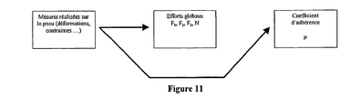
- global forces means the three force components Fx, Fy and Fz applied to the center of the wheel and the self-aligning torque N around the Z axis.
- the aim is to estimate the maximum adhesion potential of the wheel, it must be determined from the measured local potential.
- the invention detailed here differs from these local approaches. It proposes to use a measurement of the overall deformations of the tire so as to obtain information on the maximum grip potential of the wheel on the ground. Indeed, when the tire is subjected to a stress, the point of application of the forces applied in the contact area depends inter alia on the coefficient of adhesion maxi because, as soon as a part of the contact area of the wheel on the road is slipping, its contribution to tangential efforts is saturated at a level that depends on the coefficient of adhesion.
- the deformations of the tire are themselves sensitive to the displacement of this point application. In particular, the circumferential extension of the flanks, sensitive to the applied forces, is also sensitive to the displacement of the point of application of the forces in the contact area.
- the proposed method uses circumferential deformation measurements of the sidewall at certain azimuths of the tire to allow an estimation of the maximum coefficient of adhesion.
- the method requires that there be a slip zone in the contact area, whether created by a special design of the tire or by a sufficient level of stress applied to the tire.
- the invention proposes to estimate, in addition to the maximum adhesion potential, the percentage of potential used. This size indeed has the advantage of being more easily estimated in absolute value even for low stresses.
- said coefficient of adhesion ⁇ is deduced from at least 5 measurements of circumferential distance variation (extension or contraction) made in at least one sidewall of the tire, at 5 fixed points in space (that is to say fixed in the vehicle-related mark), located at different azimuths along the circumference.
- the method of the invention is based on the observation that the forces acting between the tread of the tire and the roadway and their distribution in the control area cause a significant and reproducible deformation in the form of a circumferential extension or contraction of tire flanks.
- This circumferential extension or contraction deformation if it is possible to measure it in isolation during the rotation of the tire in real time, can make it possible to know at any moment the direction and the intensity of the forces acting on the tire as well as the sign and intensity of the self-aligning torque exerted by the tire and the coefficient of grip of the tire on the roadway.
- the invention proposes to estimate the contraction or the circumferential extension of the flanks by measuring the distance between the son of the carcass ply in the flanks. It is also possible to measure the distance between yarns (for example two yarns) placed in the sidewalls and which undergo movements correlated with those of the threads of the carcass ply. We will speak later in the measure of "the gap between the son". Note that if this designation is related to the radial structure of a tire the method does not apply only to radial tires. Thus, we will speak of "son gap” to designate the average distance between two tracks made on the flank at neighboring but different azimuths.
- the circumferential extension includes a component due to the bending of the flank, especially during passage in the contact area (also known as "rabbit's belly"). This component due to bending is in no way a problem and can be used to increase the dynamics of variation of the signals used by the invention by performing the extension measurement elsewhere than on the bending neutral fiber.
- each force applied to the tire in the contact area causes a change in the circumferential extension of the tire sidewalls.
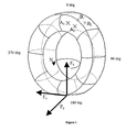
- Figure 1 two points A 1 and A 2 placed on the same radius but separated in the circumferential direction.
- On the second flank at the same azimuths as A 1 and A 2 and on the same radius, two points B 1 and B 2 are chosen.
- the distance between the two points is constant as a function of the angle of rotation of the mounted assembly.
- the azimuth ⁇ as the angle at which the circumferential extension of the flanks is analyzed.
- the origin of the azimuth is taken opposite the center of the contact area.
- the center of the contact area therefore has the 180 ° azimuth.
- the self-aligning torque N (moment around the vertical axis) is not strictly speaking another force acting between the tread of the tire and the roadway. Rather, it is a consequence of how the Fx, Fy and Fz components are applied in the contact area. If the point of application of the resultant having components Fx, Fy and Fz is not the center of the contact area, this resultant generates a moment around Oz that is called self-alignment torque. The presence of this moment is reflected mainly by a rotation of the contact area around Oz. This effect results, for example, in a circumferential extension at the contact area entrance and a circumferential contraction at the contact area exit on one side while on the other side there is a circumferential contraction at the contact area entrance. and a circumferential extension at the exit of contact area with respect to a situation with zero self-alignment torque.
- One of the advantages of the proposed method is to allow a separation of the contributions of each component of the applied stress, so as to allow an estimation of each of these components.
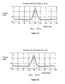
- FIG. 5 illustrates this operation by comparing a section of the part of the tire in the contact area without camber and with a camber ⁇ . This also results in a slight lateral displacement of the contact area which results in a thrust in the Y direction.
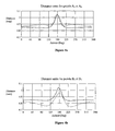
- FIGS. 6a and 6b show the evolution of the circumferential deformation in the two flanks. On the overloaded flank (Points A), the evolution is similar to that of an increase in the load. On the other side (Points B), there is an evolution compatible with a decrease in the load carried. This evolution of the signals corresponds to a rotation of the contact area around the Ox axis.
- s 1 ( ⁇ ) and s 2 ( ⁇ ) be the signals associated with the measurement of the circumferential extension on cliacun of the tire flanks and S p 1 , S i 1 , S p 2 , S i 2 their decompositions partly even and odd in azimuth.
- s p i is called an odd part in a flank and a pair in azimuth.
- s i p is called the even pair in flank and odd in azimuth.
- s i i is called odd part in flank and odd in azimuth.
- the forces Fx, Fy, Fz and the self-alignment pair N are by their orientations related to certain symmetries.
- this principle can be used to decouple the effects of the force components on the tire.
- the method explained here proposes to measure the circumferential extension on at least one sidewall of the tire. These measurements make it possible, thanks to mathematical operations (linear or nonlinear combinations between the measurements made at the different azimuths) to estimate the values of the signals s i p s p i s s p p and s i i in certain azimuths and thereby to provide an evaluation of the components of the applied force.
- the apparent rigidity of a tire comes from both its pneumatic operation (its inflation pressure) and its structural rigidity (rigidity of its architecture).
- the circumferential deformation signals measured also contain a pneumatic component and a structural component.
- the deformation signals of a tire inflated to 2 bar and loaded at 400 daN according to Z are not identical to those delivered by the same tire at 2.5 bar and loaded at 500 daN. This difference corresponds to the structural contribution and can make it possible to estimate the inflation pressure of the tire.
- FIG. 7 and 8 show such a tire.
- the rib In the area of the contact area, the rib is subjected to a vertical stress which places it against the ground. We often talk about laying flat in the footprint of the tire on the ground.
- a line formed by reference points taken from the rib so that they are aligned in the ground contact pattern are then, during the rotation of the tire, included in a plane that contains the said right defined when the points were in the contact footprint. If a drift angle is applied to the rolling tire, the plane containing the said reference points when sufficiently far from the ground contact pattern forms an angle equal to the drift angle with the reference points. when aligned in the footprint.
- the lateral force F y 1 generated by the tire is equal to the integral in the contact area of the lateral stress.
- the lateral forces are the same (same area under the curve) but the point of application of the force Fy has moved.
- the evaluation of the maximum adhesion potential uses the positioning of the force application point Fx and Fy. If the stress is sufficient (existence of a sliding zone in the contact area), this application point moves in the contact area as a function of the adhesion potential, causing a modification of the geometric positioning of the contact area. the area of contact and thus a change in the circumferential extension. Measuring the circumferential extension of the flanks in several azimuths makes it possible to obtain an estimate of the maximum adhesion coefficient, by carrying out an appropriate signal processing, as will be explained in detail.
- the azimuth ⁇ as the angle at which the circumferential extension of the flanks is analyzed.
- the origin of the azimuth is taken opposite the center of the contact area.
- the center of the contact area therefore has the 180 ° azimuth.
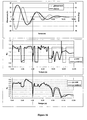
- FIGS. 12a, 12b and 12c show examples of the evolution of the circumferential extension signals obtained by a sensor implanted in the sidewall of a tire.
- the tire carries a load of 400 daN and is not subjected to any engine or braking torque.
- the solid curve presents the signals obtained on a soil of coefficient of adhesion 0.4 and the dashed curve on a soil of coefficient of adhesion 1. In this example, we highlight an effect of the coefficient of adhesion on the signal d circumferential extension.
- V1 and V2 the values of the signals at these azimuths.
- V1 + V2 is mainly related to the lateral thrust and thus the offset of the contact area (translation following Oy).
- V2-V1 is an indicator of the self-aligning torque and is therefore related to the rotation of the contact area around Oz.
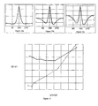
- FIG. 13 shows V2-V1 as a function of V1 + V2 for different lateral thrusts, the load being imposed at 400 daN and without motor or braking torque.
- the solid curve corresponds to a coefficient of adhesion of 0.4 and the dotted curve to a maximum coefficient of adhesion of 1. This figure shows that it is possible to distinguish the coefficient of adhesion from V1 and V2 under the driving conditions considered.
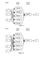
- FIG. 14 represents one of the network architectures making it possible to estimate the maximum adhesion coefficient.
- the neural network is composed of as many inputs as measurement azimuths, a layer of hidden neurons with sigmoid activation function and a linear output layer.
- the first step is to create a database containing the values of the circumferential extensions to the selected azimuths (or any representative value) that will represent the inputs of the transfer function, and containing ⁇ . It is possible to build such a database either using a measuring machine (the advantage is to be able to solicit the tire by independent forces Fx, Fy, Fz and to vary the coefficient of adhesion) either on a vehicle using for example a dynamometer wheel (to measure the forces) and by rolling on different grounds.
- a transfer function is sought using this database, where ⁇ is the output of the transfer function.
- ⁇ is the output of the transfer function.
- the third step is to check that the transfer function obtained is working correctly in the entire desired domain, ie to verify that it is generalizable.
- the first step consists in producing a database containing the values of the circumferential extensions at the selected azimuths (or any representative value) which will represent the inputs of the transfer function, and containing p u (output of the transfer function) for a set of solicitations. It is possible to build such a database either using a measuring machine (the advantage is to be able to solicit the tire by independent forces Fx, Fy, Fz and to vary the coefficient of adhesion) either on a vehicle using for example a dynamometer wheel (to measure the forces) and by rolling on different grounds.
- a transfer function is sought using this database, where pu is the output of the transfer function.
- pu is the output of the transfer function.
- it is the learning phase.
- the third step is to check that the transfer function obtained is working correctly in the entire desired domain, ie to verify that it is generalizable.
- the proposed percentage has the advantage of being more easily accurately estimated in absolute size regardless of the stress, even low, applied to the tire. It is obtained directly for example by a neural network by applying the approach presented for the estimation of ⁇ .
- Figure 16 shows an example of reconstruction of the maximum adhesion potential and the percentage of potential used. The engine or braking torque (slip related to Fx) and the transverse force (drift related to Fy) imposed. When the tire load is low (low Fx and Fy simultaneously) in the vicinity of 4 s, the quality of the estimate of the maximum grip potential drops. The estimate of the percentage of potential used remains entirely correct.
Landscapes
- Engineering & Computer Science (AREA)
- Transportation (AREA)
- Mechanical Engineering (AREA)
- General Physics & Mathematics (AREA)
- Physics & Mathematics (AREA)
- Analytical Chemistry (AREA)
- Life Sciences & Earth Sciences (AREA)
- Chemical & Material Sciences (AREA)
- Health & Medical Sciences (AREA)
- Biochemistry (AREA)
- General Health & Medical Sciences (AREA)
- Automation & Control Theory (AREA)
- Immunology (AREA)
- Pathology (AREA)
- Tires In General (AREA)
- Length Measuring Devices With Unspecified Measuring Means (AREA)
- Investigating Materials By The Use Of Optical Means Adapted For Particular Applications (AREA)
- Body Structure For Vehicles (AREA)
Claims (11)
- Verfahren zur Bestimmung des Haftungskoeffizienten µ in der Kontaktfläche eines Luftreifens auf einer Fahrbahn, dadurch gekennzeichnet, dass man mehrere raumfeste, d.h. im mit dem Fahrzeug verbundenen Koordinatensystem ortsfeste Punkte auswählt, die sich in unterschiedlichen Azimutwinkeln entlang des Umfangs in mindestens einer Flanke des Luftreifens befinden, dass man ebenso viele Messungen der Veränderung der Umfangsstrecke an diesen ortsfesten Punkten durchführt, wenn der Luftreifen auf der Fahrbahn rollt, und dass man die Messsignale so verarbeitet, dass daraus der Haftungskoeffizient µ extrahiert wird.
- Verfahren nach Anspruch 1, dadurch gekennzeichnet, dass der Haftungskoeffizient µ aus mindestens 5 Messungen der Veränderung der Umfangsstrecke abgeleitet wird, die in mindestens einer Flanke des Luftreifens an 5 raumfesten, d.h. im mit dem Fahrzeug verbundenen Koordinatensystem ortsfesten Punkten durchgeführten werden, die sich in unterschiedlichen Azimutwinkeln entlang des Umfangs befinden.
- Verfahren nach Anspruch 1 oder 2, dadurch gekennzeichnet, dass die Messung der Umfangsveränderung von mindestens einem in eine Flanke des Luftreifens integrierten Sensor durchgeführt wird, wobei das vom Sensor gelieferte Signal verarbeitet wird, um seinen Wert in mehreren Azimutwinkeln entsprechend den ortsfesten Punkten festzustellen.
- Verfahren nach Anspruch 1 oder 2, dadurch gekennzeichnet, dass die Messung der Umfangsveränderung durch ebenso viele Sensoren durchgeführt wird, wie es zu beobachtende Azimutwinkel gibt, wobei die Sensoren außerhalb des Luftreifens liegen und im ortsfesten Raum angeordnet sind.
- Verfahren nach einem der Ansprüche 1 bis 4, dadurch gekennzeichnet, dass eine Messung in drei Azimutwinkeln auf jeder der beiden Flanken, einem ausgewählten Azimutwinkel am Eingang der Kontaktfläche, bei 180°, und einem ausgewählten Azimutwinkel am Ausgang der Kontaktfläche, durchgeführt wird, wobei dieser Azimutwinkel symmetrisch zu dem am Eingang verwendeten ist.
- Verfahren nach einem der Ansprüche 1 bis 5, dadurch gekennzeichnet, dass man eine Messung in sieben Azimutwinkeln an einer einzigen Flanke durchführt, wobei die drei ersten Azimutwinkel sich am Eingang der Kontaktfläche und der vierte sich bei 180° in der Mitte der Kontaktfläche befinden, und die drei letzten bezüglich der Mitte der Kontaktfläche symmetrisch zu den drei ersten sind.
- Verfahren nach einem der Ansprüche 1 bis 6, dadurch gekennzeichnet, dass man eine Übertragungsfunktion zwischen den Messungen und dem maximalen Haftungskoeffizienten durch die folgenden Schritte erstellt:• Herstellen einer Datenbasis, die die Werte der Umfangsveränderungen in den gewählten Azimutwinkeln und die zugeordneten Werte von µ enthält, wobei die Gesamtheit der Werte experimentell festgestellt werden,• Suche einer Übertragungsfunktion mit Hilfe dieser Datenbasis, wobei µ der Ausgangswert der Übertragungsfunktion ist.
- Verfahren nach Anspruch 7, das ein Neuronennetz vom Typ Perzeptron mit einer versteckten Schicht verwendet, das als Approximator verwendet wird.
- Verfahren nach einem der Ansprüche 1 bis 8, dadurch gekennzeichnet, dass die Umfangsveränderung durch die Messung der Entfernung zwischen den Corden der Karkassenlage in den Flanken geschätzt wird.
- Verfahren nach einem der Ansprüche 1 bis 8, dadurch gekennzeichnet, dass die Umfangsveränderung durch die Messung der Entfernung zwischen einen Sensor bildenden Drähten geschätzt wird, wobei der Sensor eine Kapazitätsveränderung misst, die mit der zwei Elektroden trennenden Entfernung verbunden ist.
- Verfahren nach einem der Ansprüche 1 bis 10, dadurch gekennzeichnet, dass man den genutzten Haftungspotentialanteil bestimmt, der definiert wird durch

indem man folgendermaßen vorgeht:• Herstellen einer Datenbasis, die die Werte der Umfangsausdehnungen in den gewählten Azimutwinkeln für eine Gesamtheit von Beanspruchungen des Luftreifens enthält,• Suche einer Übertragungsfunktion mit Hilfe dieser Datenbasis, wobei pu der Ausgangswert der Übertragungsfunktion ist, wobei die Werte der Umfangsausdehnungen die Eingänge der Übertragungsfunktion sind,• Prüfen, ob die erhaltene Übertragungsfunktion im ganzen gewünschten Beanspruchungsbereich korrekt arbeitet.
Applications Claiming Priority (3)
| Application Number | Priority Date | Filing Date | Title |
|---|---|---|---|
| FR0201594A FR2835918A1 (fr) | 2002-02-08 | 2002-02-08 | Mesure de coefficient d'adherrence maximal a partir de la mesure de l'extension circonferentielle dans un flanc d'un pneu |
| FR0201594 | 2002-02-08 | ||
| PCT/EP2003/001175 WO2003066399A1 (fr) | 2002-02-08 | 2003-02-06 | Determination directe du coefficient d'adherence maximal a partir de la mesure de l'extension circonferentielle dans un flanc d'un pneu |
Publications (2)
| Publication Number | Publication Date |
|---|---|
| EP1476338A1 EP1476338A1 (de) | 2004-11-17 |
| EP1476338B1 true EP1476338B1 (de) | 2006-05-10 |
Family
ID=27620044
Family Applications (1)
| Application Number | Title | Priority Date | Filing Date |
|---|---|---|---|
| EP03704558A Expired - Lifetime EP1476338B1 (de) | 2002-02-08 | 2003-02-06 | Maximalreibwertermittlung anhand der messung der umfangausdehnung in einer reifenseitenwand |
Country Status (9)
| Country | Link |
|---|---|
| US (1) | US7099765B2 (de) |
| EP (1) | EP1476338B1 (de) |
| JP (1) | JP2005516835A (de) |
| KR (1) | KR20040094421A (de) |
| AT (1) | ATE325730T1 (de) |
| AU (1) | AU2003206851A1 (de) |
| DE (1) | DE60305153T2 (de) |
| FR (1) | FR2835918A1 (de) |
| WO (1) | WO2003066399A1 (de) |
Families Citing this family (14)
| Publication number | Priority date | Publication date | Assignee | Title |
|---|---|---|---|---|
| WO2003014693A1 (fr) * | 2001-08-06 | 2003-02-20 | Societe De Technologie Michelin | Methode de determination de composantes d'efforts subis par un pneumatique et du couple d'auto-alignement |
| US7398146B2 (en) * | 2002-06-24 | 2008-07-08 | Michelin Recherche Et Technique S.A. | Measurement of the maximum adhesion coefficient by measuring stress in a bead of a tire |
| US7827858B2 (en) * | 2004-06-30 | 2010-11-09 | Michelin Recherche Et Technique S.A. | System for estimating the maximum adherence coefficient by measuring stresses in a tire tread |
| US7780865B2 (en) * | 2006-03-31 | 2010-08-24 | Applied Materials, Inc. | Method to improve the step coverage and pattern loading for dielectric films |
| US7601651B2 (en) * | 2006-03-31 | 2009-10-13 | Applied Materials, Inc. | Method to improve the step coverage and pattern loading for dielectric films |
| US20070287301A1 (en) * | 2006-03-31 | 2007-12-13 | Huiwen Xu | Method to minimize wet etch undercuts and provide pore sealing of extreme low k (k<2.5) dielectrics |
| FR2909946B1 (fr) * | 2006-12-13 | 2010-09-17 | Soc Tech Michelin | Procede d'estimation d'un risque de defaut de liaison au sol d'un vehicule automobile |
| FR2912215B1 (fr) * | 2007-02-02 | 2010-05-14 | Michelin Soc Tech | Procede de quantification d'une utilisation d'un potentiel d'adherence maximal d'un pneumatique |
| FR2917164B1 (fr) * | 2007-06-11 | 2009-09-04 | Michelin Soc Tech | Procede d'estimation de la performance d'un pneu dans une situation de freinage. |
| FR2918478B1 (fr) * | 2007-07-04 | 2009-08-21 | Michelin Soc Tech | Procede d'estimation de la marge d'adherence disponible d'un pneumatique en roulage. |
| WO2009137056A2 (en) * | 2008-05-07 | 2009-11-12 | Bridgestone Americas Tire Operations, Llc | Method of designing a tire having a target residual aligning torque |
| FR3014807B1 (fr) | 2013-12-18 | 2016-02-05 | Michelin & Cie | Estimation du potentiel d'adherence par evaluation du rayon de roulement |
| US9650053B2 (en) * | 2014-12-03 | 2017-05-16 | The Goodyear Tire & Rubber Company | Slip ratio point optimization system and method for vehicle control |
| US12246700B2 (en) * | 2022-11-21 | 2025-03-11 | GM Global Technology Operations LLC | Machine learning-based tractive limit and wheel stability status estimation |
Family Cites Families (37)
| Publication number | Priority date | Publication date | Assignee | Title |
|---|---|---|---|---|
| US3852993A (en) | 1972-08-01 | 1974-12-10 | M Bronovets | Method of determining the frictional and mechanical properties of materials and a device for the realization thereof |
| WO1985002592A1 (fr) | 1983-12-16 | 1985-06-20 | Robert Bosch Gmbh | Procede pour determiner une valeur de glissement optimale |
| JPS63500368A (ja) | 1985-06-04 | 1988-02-12 | ロ−ベルト ボツシユ ゲゼルシヤフト ミツト ベシユレンクテル ハフツング | 最適化されたブレ−キスリツプの調整装置 |
| FR2602048A1 (fr) | 1985-12-30 | 1988-01-29 | Clerc Alain | Dispositif pour evaluer la deformation des pneumatiques de vehicules |
| DE3614379A1 (de) | 1986-04-28 | 1987-11-05 | Hofmann Gmbh & Co Kg Maschinen | Verfahren und vorrichtung zur verbesserung der laufruhe eines kraftfahrzeugrades |
| US4836257A (en) | 1986-05-08 | 1989-06-06 | Bridgestone Corporation | Pneumatic radial tire tread for reducing wandering |
| EP0363570B1 (de) | 1988-10-13 | 1996-02-21 | Japan Electronics Industry, Ltd. | Strassenoberflächen-Reibungsaufnehmer und Strassenoberflächen-Reibungskoeffizienten-Aufnehmer und Fahrzeug-Blockierschutz-Bremsanlage |
| JPH0656291B2 (ja) | 1989-04-12 | 1994-07-27 | 日産自動車販売株式会社 | ホイールアライメント測定装置 |
| DE3939917A1 (de) | 1989-12-02 | 1991-06-06 | Bosch Gmbh Robert | Vorrichtung zum bestimmen der haftreibung zwischen fahrzeugreifen und fahrbahndecke |
| US5365781A (en) | 1992-04-03 | 1994-11-22 | Michelin Recherche Et Technique S.A. | Tire uniformity correction without grinding |
| DE4435448B4 (de) | 1993-10-13 | 2007-10-11 | Volkswagen Ag | Verfahren zur permanenten Ermittlung des Fahrbahnreibwerts |
| US6021367A (en) | 1994-08-24 | 2000-02-01 | Ford Global Technologies, Inc. | Vehicle steering system and method for controlling vehicle direction through differential braking of left and right road wheels |
| DE4435160A1 (de) | 1994-09-30 | 1996-04-04 | Continental Ag | Einrichtung zur Ermittlung der Umfangskraft eines Fahrzeugrades |
| DE4439906C1 (de) * | 1994-11-08 | 1995-11-30 | Blanco Gmbh & Co Kg | Einrichtung zum Befestigen einer Einbauspüle |
| DE19646235C1 (de) * | 1996-11-08 | 1998-04-02 | Continental Ag | Fahrzeugreifen mit einer Einrichtung zur Bestimmung der Kraftschlußverhältnisse |
| US6263994B1 (en) | 1997-10-03 | 2001-07-24 | Frederick G. Eitel | Advanced motorcycle chassis steering and suspension system |
| DE19807004A1 (de) * | 1998-02-19 | 1999-09-09 | Siemens Ag | Sensorsystem und Verfahren für Überwachung/Messung des Kraftschlusses eines Fahrzeugreifens mit der Fahrbahn und weiterer physikalischer Daten des Reifens |
| DE69937702T2 (de) | 1998-04-07 | 2008-12-04 | Pirelli Tyre S.P.A. | Verfahren zur Bestimmung des Strassenverhaltens eines Fahrzeugreifens |
| US6083268A (en) | 1998-04-27 | 2000-07-04 | Bridgestone/Firestone, Inc. | Method for designing pneumatic tires for rolling conditions |
| JP4160662B2 (ja) | 1998-07-29 | 2008-10-01 | 株式会社ブリヂストン | 車両のホイールアライメント調整方法 |
| WO2000014504A1 (en) | 1998-09-07 | 2000-03-16 | Bridgestone Corporation | Tire performance predicting method |
| DE19900082C2 (de) | 1999-01-04 | 2003-09-25 | Continental Ag | Reibkraftregelsystem und Fahrzeugluftreifen mit Sensor dafür |
| US6763288B2 (en) | 1999-07-30 | 2004-07-13 | Pirelli Pneumatici S.P.A. | Method and system for monitoring and/or controlling behavior of a vehicle by measuring deformations of its tires |
| US7267148B2 (en) | 1999-08-10 | 2007-09-11 | Michelin Recherche Et Technique S.A. | Measurement of adherence between a vehicle wheel and the roadway |
| FR2797496A1 (fr) * | 1999-08-10 | 2001-02-16 | Michelin Soc Tech | Mesures d'adherence entre une roue de vehicule et la chaussee |
| JP4272317B2 (ja) | 1999-10-25 | 2009-06-03 | 株式会社ブリヂストン | タイヤ設計方法、タイヤ用加硫金型設計方法、タイヤ用加硫金型製造方法、空気入りタイヤの製造方法、タイヤ設計プログラムを記録した記録媒体 |
| US6561018B2 (en) | 1999-11-18 | 2003-05-13 | Pirelli Pneumatici S.P.A. | Method and device for monitoring the instantaneous behavior of a tire during the running of a motor vehicle |
| JP2003514707A (ja) | 1999-11-18 | 2003-04-22 | ピレリ・プネウマティチ・ソチエタ・ペル・アツィオーニ | 自動車走行時のタイヤの瞬間的な挙動を監視するための方法および装置 |
| DE10025502A1 (de) | 2000-05-23 | 2001-11-29 | Bosch Gmbh Robert | Sensorsystem zur Erfassung von Meßgrößen an einem rotierenden Gegenstand |
| US6550320B1 (en) | 2000-05-31 | 2003-04-22 | Continental Ag | System and method for predicting tire forces using tire deformation sensors |
| JP2002012160A (ja) | 2000-06-29 | 2002-01-15 | Fuji Heavy Ind Ltd | 車両の路面摩擦係数推定装置 |
| JP3271963B1 (ja) * | 2000-10-26 | 2002-04-08 | 富士重工業株式会社 | 車両の路面摩擦係数推定装置 |
| ATE409310T1 (de) | 2001-07-10 | 2008-10-15 | Michelin Soc Tech | Eine messeinrichtung beinhaltender reifen |
| WO2003014693A1 (fr) | 2001-08-06 | 2003-02-20 | Societe De Technologie Michelin | Methode de determination de composantes d'efforts subis par un pneumatique et du couple d'auto-alignement |
| WO2003014687A1 (fr) | 2001-08-06 | 2003-02-20 | Societe De Technologie Michelin | Methode de determination de caracteristiques d'un pneumatique a partir des contraintes |
| FR2835919A1 (fr) | 2002-02-08 | 2003-08-15 | Michelin Soc Tech | Mesure de coefficient d'adherence maximal a partir de la connaissance des efforts et du couple d'autoalignement generes dans l'air de contact d'un pneu |
| US7398146B2 (en) | 2002-06-24 | 2008-07-08 | Michelin Recherche Et Technique S.A. | Measurement of the maximum adhesion coefficient by measuring stress in a bead of a tire |
-
2002
- 2002-02-08 FR FR0201594A patent/FR2835918A1/fr active Pending
-
2003
- 2003-02-06 WO PCT/EP2003/001175 patent/WO2003066399A1/fr not_active Ceased
- 2003-02-06 AT AT03704558T patent/ATE325730T1/de not_active IP Right Cessation
- 2003-02-06 DE DE60305153T patent/DE60305153T2/de not_active Expired - Lifetime
- 2003-02-06 AU AU2003206851A patent/AU2003206851A1/en not_active Abandoned
- 2003-02-06 EP EP03704558A patent/EP1476338B1/de not_active Expired - Lifetime
- 2003-02-06 JP JP2003565796A patent/JP2005516835A/ja active Pending
- 2003-02-06 KR KR10-2004-7012051A patent/KR20040094421A/ko not_active Withdrawn
-
2004
- 2004-08-04 US US10/911,047 patent/US7099765B2/en not_active Expired - Lifetime
Also Published As
| Publication number | Publication date |
|---|---|
| FR2835918A1 (fr) | 2003-08-15 |
| US20050065698A1 (en) | 2005-03-24 |
| DE60305153D1 (de) | 2006-06-14 |
| WO2003066399A1 (fr) | 2003-08-14 |
| DE60305153T2 (de) | 2007-03-01 |
| AU2003206851A1 (en) | 2003-09-02 |
| ATE325730T1 (de) | 2006-06-15 |
| KR20040094421A (ko) | 2004-11-09 |
| JP2005516835A (ja) | 2005-06-09 |
| EP1476338A1 (de) | 2004-11-17 |
| US7099765B2 (en) | 2006-08-29 |
Similar Documents
| Publication | Publication Date | Title |
|---|---|---|
| EP1476339B1 (de) | Schätzung des maximalen haftungskoeffiezienten anhand der kräfte und des moments der selbstausrichtung in der aufstandsfläche eines reifens | |
| EP1417465B1 (de) | Verfahren zur bestimmung der eigenschaften eines reifens aus belastungen | |
| EP3083360B1 (de) | Schätzung des haftpotenzials durch beurteilung des rollradius | |
| EP1517822B1 (de) | Messung des maximalen haftungskoeffizients aus der belastungsmessung an einer reifenwulst | |
| EP1327131B1 (de) | Verfahren und system oder zentrale zur überwachung des reifenzustandes und zur feststellung der anwesenheit von ketten oder spikes am fahrzeug | |
| EP1417470A1 (de) | Verfahren zur bestimmung der beanspruchungskomponenten auf einen luftreifen und ein selbst-ausrichtungspaar | |
| EP1476338A1 (de) | Maximalreibwertermittlung anhand der messung der umfangausdehnung in einer reifenseitenwand | |
| US20210101603A1 (en) | Road surface condition estimation apparatus and road surface condition estimation method using the same | |
| FR2914743A1 (fr) | Procede de detection et d'estimation d'un phenomene d'hydroplanage d'un pneumatique sur une chaussee mouillee | |
| FR2980573A1 (fr) | Procede d'estimation de la resistance au roulement d'une roue de vehicule | |
| EP1290421A2 (de) | Verfahren zur erzeugung von auf einen reifen einwirkenden kraftkomponenten | |
| EP1763663A1 (de) | System zur berechnung des maximalen haftkoeffizienten mittels belastungsmessung bei einem reifenprofil | |
| EP1953052B1 (de) | Verfahren zur Quantifizierung der Verwendung einer potenziellen maximalen Bodenhaftung eines Reifens | |
| EP2416975B1 (de) | Messung von schwingungen in einem rotierenden element | |
| FR2988850A1 (fr) | Procede de detection du sens de rotation d'une roue utilisant un capteur de vitesse non signe | |
| WO2002032733A1 (fr) | Dispositif et procede pour detecter l'adherence d'un pneumatique de vehicule sur le sol | |
| EP4680505A1 (de) | Schätzung des reifenschlupfverhältnisses für zweirad- oder vierradgetriebene fahrzeuge mittels bayesischer filter | |
| FR2918749A1 (fr) | Procede d'evaluation de l'adherence transversale d'un pneu sur un sol enneige | |
| EP3068635A1 (de) | Auf fuzzy-logik basierendes entscheidungsunterstützungsverfahren zur überwachung eines kraftfahrzeugreifendrucks | |
| FR2924661A1 (fr) | Procede d'estimation d'un angle de derive d'un pneumatique. | |
| WO2015071564A1 (fr) | Pneumatique comportant un témoin d'adhérence sonore |
Legal Events
| Date | Code | Title | Description |
|---|---|---|---|
| PUAI | Public reference made under article 153(3) epc to a published international application that has entered the european phase |
Free format text: ORIGINAL CODE: 0009012 |
|
| 17P | Request for examination filed |
Effective date: 20040908 |
|
| AK | Designated contracting states |
Kind code of ref document: A1 Designated state(s): AT BE BG CH CY CZ DE DK EE ES FI FR GB GR HU IE IT LI LU MC NL PT SE SI SK TR |
|
| AX | Request for extension of the european patent |
Extension state: AL LT LV MK RO |
|
| GRAP | Despatch of communication of intention to grant a patent |
Free format text: ORIGINAL CODE: EPIDOSNIGR1 |
|
| GRAS | Grant fee paid |
Free format text: ORIGINAL CODE: EPIDOSNIGR3 |
|
| GRAA | (expected) grant |
Free format text: ORIGINAL CODE: 0009210 |
|
| AK | Designated contracting states |
Kind code of ref document: B1 Designated state(s): AT BE BG CH CY CZ DE DK EE ES FI FR GB GR HU IE IT LI LU MC NL PT SE SI SK TR |
|
| PG25 | Lapsed in a contracting state [announced via postgrant information from national office to epo] |
Ref country code: IT Free format text: LAPSE BECAUSE OF FAILURE TO SUBMIT A TRANSLATION OF THE DESCRIPTION OR TO PAY THE FEE WITHIN THE PRESCRIBED TIME-LIMIT;WARNING: LAPSES OF ITALIAN PATENTS WITH EFFECTIVE DATE BEFORE 2007 MAY HAVE OCCURRED AT ANY TIME BEFORE 2007. THE CORRECT EFFECTIVE DATE MAY BE DIFFERENT FROM THE ONE RECORDED. Effective date: 20060510 Ref country code: IE Free format text: LAPSE BECAUSE OF FAILURE TO SUBMIT A TRANSLATION OF THE DESCRIPTION OR TO PAY THE FEE WITHIN THE PRESCRIBED TIME-LIMIT Effective date: 20060510 Ref country code: NL Free format text: LAPSE BECAUSE OF FAILURE TO SUBMIT A TRANSLATION OF THE DESCRIPTION OR TO PAY THE FEE WITHIN THE PRESCRIBED TIME-LIMIT Effective date: 20060510 Ref country code: SK Free format text: LAPSE BECAUSE OF FAILURE TO SUBMIT A TRANSLATION OF THE DESCRIPTION OR TO PAY THE FEE WITHIN THE PRESCRIBED TIME-LIMIT Effective date: 20060510 Ref country code: SI Free format text: LAPSE BECAUSE OF FAILURE TO SUBMIT A TRANSLATION OF THE DESCRIPTION OR TO PAY THE FEE WITHIN THE PRESCRIBED TIME-LIMIT Effective date: 20060510 Ref country code: AT Free format text: LAPSE BECAUSE OF FAILURE TO SUBMIT A TRANSLATION OF THE DESCRIPTION OR TO PAY THE FEE WITHIN THE PRESCRIBED TIME-LIMIT Effective date: 20060510 Ref country code: FI Free format text: LAPSE BECAUSE OF FAILURE TO SUBMIT A TRANSLATION OF THE DESCRIPTION OR TO PAY THE FEE WITHIN THE PRESCRIBED TIME-LIMIT Effective date: 20060510 Ref country code: CZ Free format text: LAPSE BECAUSE OF FAILURE TO SUBMIT A TRANSLATION OF THE DESCRIPTION OR TO PAY THE FEE WITHIN THE PRESCRIBED TIME-LIMIT Effective date: 20060510 |
|
| REG | Reference to a national code |
Ref country code: GB Ref legal event code: FG4D Free format text: NOT ENGLISH |
|
| REG | Reference to a national code |
Ref country code: CH Ref legal event code: EP |
|
| REF | Corresponds to: |
Ref document number: 60305153 Country of ref document: DE Date of ref document: 20060614 Kind code of ref document: P |
|
| REG | Reference to a national code |
Ref country code: IE Ref legal event code: FG4D Free format text: LANGUAGE OF EP DOCUMENT: FRENCH |
|
| PG25 | Lapsed in a contracting state [announced via postgrant information from national office to epo] |
Ref country code: DK Free format text: LAPSE BECAUSE OF FAILURE TO SUBMIT A TRANSLATION OF THE DESCRIPTION OR TO PAY THE FEE WITHIN THE PRESCRIBED TIME-LIMIT Effective date: 20060810 Ref country code: SE Free format text: LAPSE BECAUSE OF FAILURE TO SUBMIT A TRANSLATION OF THE DESCRIPTION OR TO PAY THE FEE WITHIN THE PRESCRIBED TIME-LIMIT Effective date: 20060810 |
|
| PG25 | Lapsed in a contracting state [announced via postgrant information from national office to epo] |
Ref country code: ES Free format text: LAPSE BECAUSE OF FAILURE TO SUBMIT A TRANSLATION OF THE DESCRIPTION OR TO PAY THE FEE WITHIN THE PRESCRIBED TIME-LIMIT Effective date: 20060821 |
|
| GBT | Gb: translation of ep patent filed (gb section 77(6)(a)/1977) |
Effective date: 20060904 |
|
| PG25 | Lapsed in a contracting state [announced via postgrant information from national office to epo] |
Ref country code: PT Free format text: LAPSE BECAUSE OF FAILURE TO SUBMIT A TRANSLATION OF THE DESCRIPTION OR TO PAY THE FEE WITHIN THE PRESCRIBED TIME-LIMIT Effective date: 20061010 |
|
| NLV1 | Nl: lapsed or annulled due to failure to fulfill the requirements of art. 29p and 29m of the patents act | ||
| REG | Reference to a national code |
Ref country code: IE Ref legal event code: FD4D |
|
| PG25 | Lapsed in a contracting state [announced via postgrant information from national office to epo] |
Ref country code: LI Free format text: LAPSE BECAUSE OF NON-PAYMENT OF DUE FEES Effective date: 20070228 Ref country code: CH Free format text: LAPSE BECAUSE OF NON-PAYMENT OF DUE FEES Effective date: 20070228 Ref country code: MC Free format text: LAPSE BECAUSE OF NON-PAYMENT OF DUE FEES Effective date: 20070228 |
|
| PLBE | No opposition filed within time limit |
Free format text: ORIGINAL CODE: 0009261 |
|
| STAA | Information on the status of an ep patent application or granted ep patent |
Free format text: STATUS: NO OPPOSITION FILED WITHIN TIME LIMIT |
|
| 26N | No opposition filed |
Effective date: 20070213 |
|
| REG | Reference to a national code |
Ref country code: CH Ref legal event code: PL |
|
| BERE | Be: lapsed |
Owner name: SOC. DE TECHNOLOGIE MICHELIN Effective date: 20070228 Owner name: MICHELIN RECHERCHE ET TECHNIQUE S.A. Effective date: 20070228 |
|
| PG25 | Lapsed in a contracting state [announced via postgrant information from national office to epo] |
Ref country code: BE Free format text: LAPSE BECAUSE OF NON-PAYMENT OF DUE FEES Effective date: 20070228 |
|
| PG25 | Lapsed in a contracting state [announced via postgrant information from national office to epo] |
Ref country code: GR Free format text: LAPSE BECAUSE OF FAILURE TO SUBMIT A TRANSLATION OF THE DESCRIPTION OR TO PAY THE FEE WITHIN THE PRESCRIBED TIME-LIMIT Effective date: 20060811 |
|
| PG25 | Lapsed in a contracting state [announced via postgrant information from national office to epo] |
Ref country code: BG Free format text: LAPSE BECAUSE OF FAILURE TO SUBMIT A TRANSLATION OF THE DESCRIPTION OR TO PAY THE FEE WITHIN THE PRESCRIBED TIME-LIMIT Effective date: 20060810 |
|
| PG25 | Lapsed in a contracting state [announced via postgrant information from national office to epo] |
Ref country code: EE Free format text: LAPSE BECAUSE OF FAILURE TO SUBMIT A TRANSLATION OF THE DESCRIPTION OR TO PAY THE FEE WITHIN THE PRESCRIBED TIME-LIMIT Effective date: 20060510 |
|
| PGFP | Annual fee paid to national office [announced via postgrant information from national office to epo] |
Ref country code: GB Payment date: 20090219 Year of fee payment: 7 |
|
| PG25 | Lapsed in a contracting state [announced via postgrant information from national office to epo] |
Ref country code: CY Free format text: LAPSE BECAUSE OF FAILURE TO SUBMIT A TRANSLATION OF THE DESCRIPTION OR TO PAY THE FEE WITHIN THE PRESCRIBED TIME-LIMIT Effective date: 20060510 Ref country code: LU Free format text: LAPSE BECAUSE OF NON-PAYMENT OF DUE FEES Effective date: 20070206 |
|
| PG25 | Lapsed in a contracting state [announced via postgrant information from national office to epo] |
Ref country code: HU Free format text: LAPSE BECAUSE OF FAILURE TO SUBMIT A TRANSLATION OF THE DESCRIPTION OR TO PAY THE FEE WITHIN THE PRESCRIBED TIME-LIMIT Effective date: 20061111 Ref country code: TR Free format text: LAPSE BECAUSE OF FAILURE TO SUBMIT A TRANSLATION OF THE DESCRIPTION OR TO PAY THE FEE WITHIN THE PRESCRIBED TIME-LIMIT Effective date: 20060510 |
|
| GBPC | Gb: european patent ceased through non-payment of renewal fee |
Effective date: 20100206 |
|
| PG25 | Lapsed in a contracting state [announced via postgrant information from national office to epo] |
Ref country code: GB Free format text: LAPSE BECAUSE OF NON-PAYMENT OF DUE FEES Effective date: 20100206 |
|
| PGFP | Annual fee paid to national office [announced via postgrant information from national office to epo] |
Ref country code: IT Payment date: 20140227 Year of fee payment: 12 |
|
| PG25 | Lapsed in a contracting state [announced via postgrant information from national office to epo] |
Ref country code: IT Free format text: LAPSE BECAUSE OF NON-PAYMENT OF DUE FEES Effective date: 20150206 |
|
| REG | Reference to a national code |
Ref country code: FR Ref legal event code: PLFP Year of fee payment: 14 |
|
| REG | Reference to a national code |
Ref country code: FR Ref legal event code: PLFP Year of fee payment: 15 |
|
| REG | Reference to a national code |
Ref country code: FR Ref legal event code: PLFP Year of fee payment: 16 |
|
| PGFP | Annual fee paid to national office [announced via postgrant information from national office to epo] |
Ref country code: DE Payment date: 20180219 Year of fee payment: 16 |
|
| PGFP | Annual fee paid to national office [announced via postgrant information from national office to epo] |
Ref country code: FR Payment date: 20180223 Year of fee payment: 16 |
|
| REG | Reference to a national code |
Ref country code: DE Ref legal event code: R119 Ref document number: 60305153 Country of ref document: DE |
|
| PG25 | Lapsed in a contracting state [announced via postgrant information from national office to epo] |
Ref country code: DE Free format text: LAPSE BECAUSE OF NON-PAYMENT OF DUE FEES Effective date: 20190903 |
|
| PG25 | Lapsed in a contracting state [announced via postgrant information from national office to epo] |
Ref country code: FR Free format text: LAPSE BECAUSE OF NON-PAYMENT OF DUE FEES Effective date: 20190228 |