EP1477053A2 - Dispositif et procédé pour orienter des plantes de légume et de laitue, dispositif de plantation pour des plantes de légume et de laitue et système et procédé pour récolter et orienter des plantes de légume et de laitue - Google Patents
Dispositif et procédé pour orienter des plantes de légume et de laitue, dispositif de plantation pour des plantes de légume et de laitue et système et procédé pour récolter et orienter des plantes de légume et de laitue Download PDFInfo
- Publication number
- EP1477053A2 EP1477053A2 EP04017745A EP04017745A EP1477053A2 EP 1477053 A2 EP1477053 A2 EP 1477053A2 EP 04017745 A EP04017745 A EP 04017745A EP 04017745 A EP04017745 A EP 04017745A EP 1477053 A2 EP1477053 A2 EP 1477053A2
- Authority
- EP
- European Patent Office
- Prior art keywords
- plants
- plant
- planting
- lettuce
- attachment
- Prior art date
- Legal status (The legal status is an assumption and is not a legal conclusion. Google has not performed a legal analysis and makes no representation as to the accuracy of the status listed.)
- Granted
Links
Images






Classifications
-
- A—HUMAN NECESSITIES
- A01—AGRICULTURE; FORESTRY; ANIMAL HUSBANDRY; HUNTING; TRAPPING; FISHING
- A01C—PLANTING; SOWING; FERTILISING
- A01C11/00—Transplanting machines
Definitions
- the invention relates to a device for aligning vegetable or salad plants. Furthermore, the invention relates to a planting device for vegetable or Salad plants and devices for removing the plants from such a device. Finally, the invention relates to systems and methods that the invention Alignment device and the planting device according to the invention combine.
- Vegetable or lettuce plants e.g. Chicory or endive salad
- the plants must be taken up individually and the Roots are cut off before the heads e.g. packed and for distribution to get prepared.
- the individual plants may have to be cut by hand what a high workload and time-consuming processing means. With every manual or machine cutting process there is also Risk of root parts remaining on the head or recyclable material from the Be cut off with the root.
- the object of the present invention is to provide devices and methods to provide the planting and harvesting or processing of the vegetable or Simplify lettuce plants.
- the device according to the invention has two conveyor belts between the lettuce or vegetable plants can move.
- One thing moves the belts at higher speed, so that the plants start rotating become.
- the plant is oriented vertically around an axis that goes through the head and root area.
- the plant tends to stand up in such a way that the conveyor belts between them keep the narrowest part of the plant, i.e. the connection area between Head and root.
- the conveyor belts that pinch the plant between them thus additionally cause the plant to be above the conveyor belts the head is located and below the root. This height alignment is supported by the Rotation favors.
- the salad or vegetable plant an optimal orientation in the vertical direction, with all plants conveyed by the conveyor belts with the connecting area between Head and root are arranged at the same height. In this way creates a defined state that is the same for all transported plants, so that further processing is very easily possible and easy to design.
- the belts can be used with to be roughened.
- the distance between the bands can be advantageously adjust to the material to be processed.
- the tapes can do a certain amount Flexibility to a certain bias against the plants too produce.
- the conveyor belts that hold the plant between them are designed as counter-rotating endless belts that are driven in this way are that the movement of the conveyor belts in the area where they are Transport plants, is rectified.
- an obstacle can advantageously be provided be that below in the infeed area between the conveyor belts this is arranged so that a plant that is being transported has its roots on hits the obstacle. This creates an inclined position of the plant that affects it Way tilts between the conveyor belts. Both the initiation of the rotation process as well as the vertical height orientation of the plant positively promoted.
- the device according to the invention for alignment are two parallel alignment belts below the conveyor belts provided that aligning through the head and root area going axis of the vegetable or salad plants in a substantially vertical Support direction.
- the running direction of these alignment bands and the running direction of the conveyor belts form an angle to one another so that the distance of the alignment belts and the conveyor belts along the transport direction increased.
- the alignment belts are arranged such that they the root area of the vegetable or salad plant during its through the conveyor belts generated translation movement from one side, so the Root areas of the vegetable or salad plant during their translational Pull movement down.
- the alignment belts are simply designed as endless belts that run in opposite directions are driven so that their movement in the area in which they the plant grasp between them is rectified.
- the two alignment belts can be moved at the same speed with each other. Due to the rotational movement of the vegetable or lettuce plants, caused by the different Speed of the conveyor belts is created some friction between the alignment bands and the roots of the Plants. This friction can advantageously be used to align to support.
- the alignment tapes each driven at the speed of the conveyor belt above. In this way, the alignment belts support the rotational movement the plants that are already initiating an alignment of the plants and their positioning effected in the same amount. Such a configuration is particularly gentle beneficial for the plant and in particular, even if the root the plant is to be processed further.
- the alignment device according to the invention can be used at any point in the processing process be used with a precise height alignment and Alignment of plants required.
- a cutting device for separation of the head serves from the roots.
- Such a cutting device can e.g. a Have blade that at the connection area between the head and root of the Plants intervenes.
- Conveyor belts are provided which accommodate the individual elements.
- the plants are rotated about an approximately vertical axis, to achieve the approximately vertical alignment with a defined altitude.
- the method according to the invention can be used particularly effectively, if after the essentially vertical alignment with a defined altitude the heads of the plants are separated from the roots using a cutting device become.
- the plant device according to the invention for vegetable or salad plants has Support frame for a planting attachment, which includes mountains and valleys, so that the Roots of plants in the valleys can be taken.
- the plants can be regular in a defined manner to be ordered.
- the plants can be planted in from the plant attachment with mountains and valleys very easily slide out laterally or lift up after if necessary, the planting attachment has been removed from the support frame.
- the planting device thus simplifies both planting and harvesting and thus saves time and money.
- the support frame can be a simple holder or a table-like Frame structure.
- the plant attachment can also be used without a support frame become.
- the planting attachment can be firmly connected to the support frame, whereby for removal the plants may then have to move the entire device.
- the planting attachment can be removed individually without the support frame, to e.g. to be able to be used in a harvesting device, the machine pushes the plants out of the device along the valleys.
- the mountains and valleys of the planting attachment can be made in different ways different materials. However, one embodiment is particularly simple, where a bent metal is used. Such a curved one Metal can e.g. be shaped in a zigzag shape or in a wave shape.
- a further development of this device provides that the planting attachment is flexible. This can be done before or during the pushing of the plants out of the valleys the metal is bent such that the valleys are spread out. To this The removal is made even easier.
- An embodiment of a device according to the invention as claimed in claim 15 to remove the vegetable or salad plants from an inventive Planting device has one or more displaceable pistons, which in corresponding Intervene valleys of the plant according to the invention and such are movable that they push the plants out of the valleys.
- a piston can be provided to empty one valley after the other.
- several pistons lying next to one another are provided, that can be moved at the same time to empty several valleys at the same time.
- the position of the Pistons adapted to the displacement of the valleys by bending the top.
- the emptying device according to the invention can also be used for mounts include the planting attachment, which may hold it in a bent position.
- the device according to the invention for removing the vegetable or salad plants can also be used to push plants out of a plant are used that does not include a support frame.
- the devices according to the invention can be particularly advantageously combined into one Combine system that a device for removing vegetables or Lettuce plants e.g. from a plant device according to the invention with a plant according to the invention Alignment device combined and subject of the claim 22 is.
- the corresponding method according to the invention is the subject of the claim 28.
- the alignment device is arranged such that the plants, if using the above embodiment of the removal device from the planting device be pushed, are picked up by the alignment device and aligned for further processing and transported away.
- FIG. 19 Another embodiment of a device according to the invention 19 for removing vegetable or lettuce plants from a plant has a screw device which has a number of rotatably drivable Screws carries approximately the number of rows in a plant ingestible plants. This is on a movable suspension Screw device mounted to be spatially movable. The screw device and the suspension are designed such that the screws of the screw device can be driven into the plants that are in a plant are on a holder in the device according to the invention.
- a removal device is very simple Way to remove a number of plants from a plant.
- the screws are screwed into the individual plants and thus secure one safe transportation.
- With the movable suspension the screws moved up with the plants and so out of the plant removed.
- a plant device is advantageously used.
- other planting devices can also be used, z. B. planting equipment, the plant attachment individual, preferably square Has plant cells.
- the planting device can in turn be designed flexibly in order to be removed to further simplify.
- the movable suspension moves the screws together with the plants, for example to a transport facility.
- a such a removal device can be used in an advantageous development Example consist of endless recording tapes that are driven in opposite directions be in the area in which they grasp the plants, in the move in the same direction. The plants are between these tapes with the help of the movable suspension of the embodiment of the invention Removal device inserted and removed by the movement of the conveyor belts.
- the Bracket for the plant attachment of a plant can be movably mounted. This way, after removing a row and passing it on to the tapes the bracket can be moved a row so that the Screw device can drive the screws into the next row.
- the suspension is movably mounted, that it can be moved over a plant attachment that is on the bracket located.
- the holder can in turn be the same as for the first embodiment be such that the flexible plant attachment under tension Can be kept to hold the recordings for the plants for easier removal dilate.
- the screws can e.g. be driven into the plant from above. Especially however, it is advantageous if the screws are inserted obliquely into the plants to remove them from the plant. This prevents that the plants turn when screwing in.
- the screws are advantageous arranged so that they start in the root area.
- the alignment device according to the invention can also be used particularly advantageously combine this configuration of the removal device into a system that a device for removing vegetable or salad plants e.g. from one Planting device combined with an alignment device according to the invention and Subject of claim 23 is.
- the alignment device is arranged in such a way that the plants, when transported by the conveyor belts, get into the inlet area of an alignment device according to the invention. There they are then aligned for further processing and transported away.
- the Corresponding method according to the invention is the subject of claim 29.
- endless belts 3 and 5 are shown, which move in the direction 7 and 9 respectively.
- the endless belt 3 is set in rotation at a higher speed than the endless belt 5, so that the schematically indicated salad or Turn vegetables 1 around their own vertical axis in the direction of 8. there only two plants 1 are indicated schematically.
- the distance between the conveyor belts 3, 5 is set so that it corresponds approximately to the thickness of the connection area between the head and root of the plant.
- the conveyor belts 3 and 5 are arranged displaceably with respect to one another.
- the surface of the conveyor belts 3, 5 is optionally designed to be sufficiently rough so that the plants 1 can be gripped, transported and rotated safely.
- the spacing of the bands is set approximately to the lateral extent of the plants, the bands being flexible in order to hold the plants firmly.
- rollers 11 and 13 indicate the deflection rollers for the conveyor belts 3 and 5, either the rollers 11 or the rollers 13 are driven.
- 15 denotes a rod, which is arranged below the conveyor belts 3 and 5 is at a height that a normal plant to be transported with its roots stuck to this obstacle.
- 25 denotes a cutting device, which are arranged in the end region of the transport region of the belts 3 and 5 is that a blade is directly at the connection area between the head and the Root of plant 1 either directly above or directly below the conveyor belts can attack.
- the root falls on a conveyor belt 17 and is in the direction 19 transported away while the head falls on a conveyor belt 21 and in the direction of 23 is transported away.
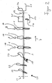
- Fig. 2 the same embodiment is shown schematically from the side.
- Designated 10 the axis of rotation about which the aligned plants 1 by the different Speed of the conveyor belts 3, 5 can be rotated.
- At 29 are Plants shown that get in a random orientation between the conveyor belts are, whereby neither the room orientation nor the altitude are defined.
- 27 shows a plant with its root abutting the obstacle 15 and so in Is tilted.
- the axes of rotation of the deflection rollers are in FIG. 2 11 and 13 visible.
- Finally shows in the end of the conveyor belts Number 1a a severed head as it falls onto the conveyor belt 21 and 1b the separated root, which is transported away from the conveyor belt 17.
- Fig. 3 shows a plant 1 which is rotated about its axis 10, the Direction of view along the transport direction through the conveyor belts 3 and 5.
- Fig. 4 shows the same plant just before the head 1a is separated from the root 1b becomes.
- the plant is located between the conveyor belts 3 and 5 in the area of the cutting device 25.
- This has a blade 24 which is oriented in the direction 26 is movable to separate the head 1a from the root 1b.
- This is not one shown control provided that the cutting device in a corresponding Beat moves.
- a rotating blade may be provided or several blades, which are arranged in a star shape and rotate around the heads 1a separate from each of the roots 1b.
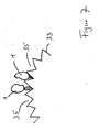
- FIG. 5 shows a sectional view from the side of a plant device according to the invention.
- the frame 31 is visible, in which a zigzag curved Metal 33 is located.
- the location of planted plants is indicated schematically 1, which with its roots bent into the valleys 35 between the mountains 37 of the Metal 33 are enough.
- the earth In the valleys 35 the earth is to be placed, into which the root of plants 1 protrudes. Deviating from this can also be provided instead of the earth be that the plant attachment contains a nutrient solution or water or of it is flowed through.
- the bent metal 33 can be moved in the direction 39 from the frame Remove 31 so that the faces of the valleys 35 can be exposed.
- FIG. 6 shows a schematic top view of the device according to the invention with the indicated valleys 35, in which the plants 1 are located. As lines The mountains 37 between the valleys 35 are indicated.
- the metal can also be wavy be curved without sharp zigzag edges.
- Fig. 7 shows a metal 33 before the removal process.
- the metal 33 is flexible configured so that, as indicated in Fig. 7, an expansion of the valleys 35 by Bending the metal is possible.
- FIG. 8a shows the use of the alignment device 300 according to the invention in the Picking up plants from a plant device 200 according to the invention. Furthermore, FIG. 8a shows a thrust device 41 with a piston 43 which is directed in the direction 45 can be moved to the plants 1 from the planting device 200 slide out to the alignment device 300.
- the pusher is at 100 designated.
- Fig. 8b shows the pushing out process in an advanced stage with the extended Piston 43.
- An embodiment is shown with a piston 43 for pushing out one Row of plants 1 from a valley 35 of a plant attachment 33.
- a plurality of pistons 43 can be provided side by side around the plants a corresponding number of adjacent valleys 35 in one Empty planting attachment 33 at the same time. If necessary, a corresponding one Number of alignment devices 300 to be provided in a parallel arrangement.
- the plants e.g. Chicory or endive salad plants are in an inventive Planting device set, its orientation is such that the Roots grow in the valleys 35 of the metal frame 33, in which there are corresponding ones Soil and / or fertilizer can be.
- the plant attachment 33 is grown with plants 1 in the direction 39 of the Frame 31 lifted off.
- the sheet 33 can be bent in the manner shown in FIG any soil present in the valleys 35 to be detached from the mountains 37.
- the metal 33 is brought in front of the pusher 100.
- the pusher may include one or more pistons 43 that are adjacent Valleys 35 of the plant attachment 33 can intervene to the plants 1 to slide out of the valleys 35 along the valleys 35 in the direction 45.
- the piston 43 is moved and pushes, as can be seen in FIGS. 8a and 8b Plants out of the valleys 35 of the plant attachment 33.
- the plants fall between the conveyor belts 3 and 5 of the alignment device 300 they have an irregular orientation, both in height and in spatial orientation, as the plant 29 is to symbolize in FIGS. 8a and 8b.
- the planting attachment 33 is made of flexible material, the planting attachment can also in a bent state, as can be seen in FIG. 7, in front of a Thrust device 100 are brought, the correspondingly arranged offset Piston 43 has to align the plants 1 on appropriately arranged alignment devices 300 to push.
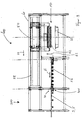
- FIG. 33 Another embodiment according to the invention is shown in FIG.
- This system has no removal device with a sliding device.
- 33 designated again a plant attachment according to the invention.
- 50 denotes one Screw device which is attached to a suspension 54.
- the screw device comprises individual screws 52 which, e.g. from a controller, not shown controlled, can be rotated.
- the suspension 54 is open a rail device 58 slidably mounted.
- the suspension also includes 54 a mechanism by means of which the screw device 50 in Can be pulled up towards 62.
- the special design of this facility for the sake of clarity is not shown in FIG. 9 and can e.g. can be realized mechanically.
- the suspension 54 with the rail device 58 is fastened in a frame 60.
- the movement of the screw device 52 in the direction of the rail device 58 is denoted by 62.
- a translational movement along the rail device 58 is designated by 64.
- the endless receiving tapes 56 have such a distance that they are to be transported Can pick up plants between them and transport them safely. They are transported to a transfer area 301, in which the plants are in a Inlet area 28 of an alignment device 300 according to the invention Conveyor belts 3 and 5 can be handed over.
- the whole of the suspension device 54 with the screw device 52 and the driven receiving tapes 66 in the frame 60 provides the removal device 400 according to this Embodiment.
- Fig. 10 a view is shown in which the screw device 50 in the suspension 54 is visible. It can be clearly seen that the arrangement of the screw device 50 and the suspension 54 is inclined, so that the screws 52 also are arranged at an angle. 10 there is also a planting attachment 33 with the valleys 35 and mountains 37 already described, in which planted Salad or vegetable plants 1 are. The location of the screws 52 with Reference to the plant attachment 33 is such that the screws are usually the Root area of plants 1 hit when they are screwed into the plants at an angle become.
- the plants are in turn placed in a plant according to the invention, so that after the plants have grown out, a state arises as in 5 is indicated and has already been described above.
- the planting attachment 33 is lifted off the frame 31 with the fully grown plants 1 in the direction 39.
- the sheet 33 of the type shown in Fig. 7 can be bent if necessary in order to detach any earth present in the valleys 35 from the mountains 37.
- the metal 33 is in the inventive embodiment 400 of the removal device introduced according to FIG. 9. To do this, it is stored on a bracket, which is not shown in FIG. 9 for the sake of clarity.
- the screws 52 are in a row of plants 1 screwed in.
- the row of screws is arranged such that in usually every plant is hit by a screw.
- the screws hit a row at the same time of plants 1 located in a valley 35. Deviating from this can Of course, the plant attachment 33 are applied offset by 90 °, so that always a plant 1 from each valley 35 is hit by a screw.
- Such a removal device 400 according to the invention can also be used with a differently designed plant attachment can be used, the z. B. square Plant recordings.
- the plants 1 are in a row which is located on the screwing device 50, guided between the receiving bands 56, so by a screwing movement the screws 52 in the opposite direction, the screws from the plants 1 unscrewed so that the plants can be transported freely in the direction of 66 is possible. It can also be provided that the endless receiving tapes 56 can only be brought to the side of the plants 1 at this moment. To do this a control, not shown, give a corresponding signal when the suspension 54 reached completely above the area of the receiving belts 56 is.
- the plants 1 leave the receiving belts 56 and enter the inlet area 28 of the alignment device 300 according to the invention a, which has already been explained with reference to Figures 1 to 4.
- the further function of the alignment device corresponds to that already described Embodiment.
- FIG. 11 shows a further embodiment of a system according to the invention with a further embodiment of an alignment device according to the invention 500.
- the removal device 400 of FIG. 11 corresponds to the removal device 400 of Figure 9.
- the embodiment 500 includes alignment bands 503, 505 extending from the lead-in area 28 at an angle Guide 507 downwards at an angle.
- the alignment belts 503, 505 are circumferential Endless belts designed in the same direction as those above Move conveyor belts 3, 5.
- the angle 507 is chosen so that the maximum distance of the alignment belts 503, 505 from the conveyor belts 3, 5 in about the extent of the root 1 b of a vegetable or salad plant to be treated 1 corresponds.
- Alignment belts 503, 505 capture the root area 1 b of the plant between them. Through the movement the alignment tapes diagonally downwards align the vegetables or lettuce plants supported. The root is pulled down along the movement and aligns the plant.
- this embodiment 500 of the alignment device can also with other embodiments of removal devices 100 according to the invention, 200 are used, as explained with reference to FIG. 8.
- the invention thus enables simple and safe alignment of the plants, e.g. a defined cutting of the head from the roots in a simple way allows.
- the plants With the device according to the invention, the plants become like this aligned that they are always with the same area at the same height between get the cutting device.
Landscapes
- Life Sciences & Earth Sciences (AREA)
- Soil Sciences (AREA)
- Environmental Sciences (AREA)
- Harvesting Machines For Root Crops (AREA)
- Apparatuses For Bulk Treatment Of Fruits And Vegetables And Apparatuses For Preparing Feeds (AREA)
Applications Claiming Priority (5)
| Application Number | Priority Date | Filing Date | Title |
|---|---|---|---|
| DE10036403 | 2000-07-26 | ||
| DE10036403 | 2000-07-26 | ||
| DE10057445A DE10057445A1 (de) | 2000-07-26 | 2000-11-20 | Vorrichtung und Verfahren zum Ausrichten von Gemüse- und Salatpflanzen, Pflanzeinrichtung für Gemüse- und Salatpflanzen und System und Verfahren zum Ernten und Ausrichten von Gemüse- oder Salatpflanzen |
| DE10057445 | 2000-11-20 | ||
| EP01118158A EP1179290B1 (fr) | 2000-07-26 | 2001-07-26 | Dispositif et procédé pour orienter des plantes de légume et de laitue. |
Related Parent Applications (1)
| Application Number | Title | Priority Date | Filing Date |
|---|---|---|---|
| EP01118158A Division EP1179290B1 (fr) | 2000-07-26 | 2001-07-26 | Dispositif et procédé pour orienter des plantes de légume et de laitue. |
Publications (3)
| Publication Number | Publication Date |
|---|---|
| EP1477053A2 true EP1477053A2 (fr) | 2004-11-17 |
| EP1477053A3 EP1477053A3 (fr) | 2004-12-29 |
| EP1477053B1 EP1477053B1 (fr) | 2007-01-10 |
Family
ID=7650286
Family Applications (1)
| Application Number | Title | Priority Date | Filing Date |
|---|---|---|---|
| EP04017745A Expired - Lifetime EP1477053B1 (fr) | 2000-07-26 | 2001-07-26 | Dispositif et prodédé pour l'extraction d'une rangée des plantes de légume et de laitue d'une grille de plantes |
Country Status (2)
| Country | Link |
|---|---|
| EP (1) | EP1477053B1 (fr) |
| DE (1) | DE10057445A1 (fr) |
Cited By (2)
| Publication number | Priority date | Publication date | Assignee | Title |
|---|---|---|---|---|
| CN112570309A (zh) * | 2020-12-01 | 2021-03-30 | 昆山和谐山川五金科技有限公司 | 一种五金件混料影像筛选机 |
| CN114467489A (zh) * | 2021-09-21 | 2022-05-13 | 绍兴春茗科技有限公司 | 一种采茶机的送料机构 |
Families Citing this family (2)
| Publication number | Priority date | Publication date | Assignee | Title |
|---|---|---|---|---|
| CN113396675B (zh) * | 2021-05-26 | 2022-04-26 | 宁夏任进礼新连栋温室技术发展有限公司 | 温室蔬菜种植全程作业的一体化装备以及藤蔓类蔬菜种植方法 |
| US20240049646A1 (en) * | 2022-08-09 | 2024-02-15 | Bowery Farming | Systems, methods, and devices for harvesting plants with an ultrasonic blade |
Family Cites Families (4)
| Publication number | Priority date | Publication date | Assignee | Title |
|---|---|---|---|---|
| FI84870C (fi) * | 1987-11-02 | 1992-02-10 | Laennen Tehtaat Oy | Foerfarande och anordning foer plantering av klumpplantor. |
| US4998945A (en) * | 1988-12-14 | 1991-03-12 | National Research Development Corporation | Transplanting equipment |
| FR2662046B1 (fr) * | 1990-05-15 | 1992-08-21 | Gregoire Besson Ets | Machine a planter ou a repiquer. |
| US5365693A (en) * | 1992-09-10 | 1994-11-22 | Metrolina Greenhouses, Inc. | Method and apparatus for transplanting plants from one container to another |
-
2000
- 2000-11-20 DE DE10057445A patent/DE10057445A1/de not_active Withdrawn
-
2001
- 2001-07-26 EP EP04017745A patent/EP1477053B1/fr not_active Expired - Lifetime
Cited By (2)
| Publication number | Priority date | Publication date | Assignee | Title |
|---|---|---|---|---|
| CN112570309A (zh) * | 2020-12-01 | 2021-03-30 | 昆山和谐山川五金科技有限公司 | 一种五金件混料影像筛选机 |
| CN114467489A (zh) * | 2021-09-21 | 2022-05-13 | 绍兴春茗科技有限公司 | 一种采茶机的送料机构 |
Also Published As
| Publication number | Publication date |
|---|---|
| EP1477053B1 (fr) | 2007-01-10 |
| EP1477053A3 (fr) | 2004-12-29 |
| DE10057445A1 (de) | 2002-02-07 |
Similar Documents
| Publication | Publication Date | Title |
|---|---|---|
| EP1106048B1 (fr) | Dispositif d'introduction et de cueillage d'un dispositif de chargement de récoltes | |
| DE3304098C2 (de) | Pflanzmaschine | |
| DE2854913A1 (de) | Schnellpflanzverfahren und -maschine | |
| EP0093318A2 (fr) | Machine à découenner | |
| DE1816117A1 (de) | Verfahren und Vorrichtung zum Trennen der unterschiedlichen Bestandteile von Zuckerrohr | |
| DE3046132A1 (de) | Erntemaschine | |
| EP3322304B1 (fr) | Méthode et dispositif d'ouverture de cabosses de cacao | |
| DE2729366C3 (de) | Vorrichtung zum Abzupfen von Stiele und Blütenkelche von Früchten | |
| DE69205283T2 (de) | Erntemaschine. | |
| EP1477053B1 (fr) | Dispositif et prodédé pour l'extraction d'une rangée des plantes de légume et de laitue d'une grille de plantes | |
| EP1179290B1 (fr) | Dispositif et procédé pour orienter des plantes de légume et de laitue. | |
| DE102005025482A1 (de) | Verfahren zum Abtrennen eines Fischkopfes und Vorrichtung zum Ausrichten eines Fischkörpers | |
| DE3414089A1 (de) | Vorrichtung zum ausheben von in formen einer gefriermaschine gefrorenen koerpern | |
| DE69008323T2 (de) | Pflanzensetzmaschine. | |
| DE3605639A1 (de) | Vorrichtung zum schaelen von zwiebeln | |
| EP2457443B1 (fr) | Procédé de torsion mécanique de bandes de pâte | |
| CH662708A5 (de) | Vorrichtung zum auflockern und ausgeben von blattfoermigem material. | |
| DE2459883A1 (de) | Vorrichtung zum schneiden und ernten von mais unter verwendung gegensinnig rotierender foerderkreisel | |
| DE3101735A1 (de) | Verfahren und vorrichtung zur foerderung von pflanzenzellen in einer pflanzmaschine | |
| AT248775B (de) | Erntemaschine für Mohnköpfe | |
| DE2416624A1 (de) | Verteilvorrichtung fuer geschnittene, scheibenfoermige produkte | |
| DE1611878C3 (de) | Vorrichtung zur Überführung einer Anzahl von nebeneinanderliegenden Reihen dicht benachbarter einzelner Wareneinheiten In eine einzige Reihe, insbesondere an einer Verpackungsanlage | |
| DE1196894B (de) | Mohnkapsel-Erntemaschine | |
| DE2617557A1 (de) | Vorrichtung fuer die automatische uebergabe von teigstuecken auf eine bewegliche foerderflaeche, insbesondere fuer die uebergabe von teigstuecken von einer gaerungszelle auf die darunter liegende bewegliche foerderflaeche | |
| DE632805C (de) | Ablegevorrichtung fuer Aufschnittschneidemaschinen |
Legal Events
| Date | Code | Title | Description |
|---|---|---|---|
| PUAI | Public reference made under article 153(3) epc to a published international application that has entered the european phase |
Free format text: ORIGINAL CODE: 0009012 |
|
| PUAL | Search report despatched |
Free format text: ORIGINAL CODE: 0009013 |
|
| 17P | Request for examination filed |
Effective date: 20040727 |
|
| AC | Divisional application: reference to earlier application |
Ref document number: 1179290 Country of ref document: EP Kind code of ref document: P |
|
| AK | Designated contracting states |
Kind code of ref document: A2 Designated state(s): AT BE CH CY DE DK ES FI FR GB GR IE IT LI LU MC NL PT SE TR |
|
| AK | Designated contracting states |
Kind code of ref document: A3 Designated state(s): AT BE CH CY DE DK ES FI FR GB GR IE IT LI LU MC NL PT SE TR |
|
| 17Q | First examination report despatched |
Effective date: 20050520 |
|
| AKX | Designation fees paid |
Designated state(s): AT BE CH CY DE DK ES FI FR GB GR IE IT LI LU MC NL PT SE TR |
|
| GRAP | Despatch of communication of intention to grant a patent |
Free format text: ORIGINAL CODE: EPIDOSNIGR1 |
|
| RTI1 | Title (correction) |
Free format text: DEVICE AND METHOD FOR EXTRACTION OF A ROW OF LETTUCE AND VEGETABLE PLANTS FROM A PLANT ATTACHMENT |
|
| GRAS | Grant fee paid |
Free format text: ORIGINAL CODE: EPIDOSNIGR3 |
|
| GRAA | (expected) grant |
Free format text: ORIGINAL CODE: 0009210 |
|
| AC | Divisional application: reference to earlier application |
Ref document number: 1179290 Country of ref document: EP Kind code of ref document: P |
|
| AK | Designated contracting states |
Kind code of ref document: B1 Designated state(s): AT BE CH CY DE DK ES FI FR GB GR IE IT LI LU MC NL PT SE TR |
|
| PG25 | Lapsed in a contracting state [announced via postgrant information from national office to epo] |
Ref country code: IE Free format text: LAPSE BECAUSE OF FAILURE TO SUBMIT A TRANSLATION OF THE DESCRIPTION OR TO PAY THE FEE WITHIN THE PRESCRIBED TIME-LIMIT Effective date: 20070110 Ref country code: DK Free format text: LAPSE BECAUSE OF FAILURE TO SUBMIT A TRANSLATION OF THE DESCRIPTION OR TO PAY THE FEE WITHIN THE PRESCRIBED TIME-LIMIT Effective date: 20070110 Ref country code: FI Free format text: LAPSE BECAUSE OF FAILURE TO SUBMIT A TRANSLATION OF THE DESCRIPTION OR TO PAY THE FEE WITHIN THE PRESCRIBED TIME-LIMIT Effective date: 20070110 |
|
| REG | Reference to a national code |
Ref country code: GB Ref legal event code: FG4D Free format text: NOT ENGLISH |
|
| REG | Reference to a national code |
Ref country code: IE Ref legal event code: FG4D Free format text: LANGUAGE OF EP DOCUMENT: GERMAN |
|
| REF | Corresponds to: |
Ref document number: 50111877 Country of ref document: DE Date of ref document: 20070222 Kind code of ref document: P |
|
| PG25 | Lapsed in a contracting state [announced via postgrant information from national office to epo] |
Ref country code: SE Free format text: LAPSE BECAUSE OF FAILURE TO SUBMIT A TRANSLATION OF THE DESCRIPTION OR TO PAY THE FEE WITHIN THE PRESCRIBED TIME-LIMIT Effective date: 20070410 |
|
| PG25 | Lapsed in a contracting state [announced via postgrant information from national office to epo] |
Ref country code: ES Free format text: LAPSE BECAUSE OF FAILURE TO SUBMIT A TRANSLATION OF THE DESCRIPTION OR TO PAY THE FEE WITHIN THE PRESCRIBED TIME-LIMIT Effective date: 20070421 |
|
| PG25 | Lapsed in a contracting state [announced via postgrant information from national office to epo] |
Ref country code: PT Free format text: LAPSE BECAUSE OF FAILURE TO SUBMIT A TRANSLATION OF THE DESCRIPTION OR TO PAY THE FEE WITHIN THE PRESCRIBED TIME-LIMIT Effective date: 20070611 |
|
| ET | Fr: translation filed | ||
| GBV | Gb: ep patent (uk) treated as always having been void in accordance with gb section 77(7)/1977 [no translation filed] |
Effective date: 20070110 |
|
| REG | Reference to a national code |
Ref country code: IE Ref legal event code: FD4D |
|
| PLBE | No opposition filed within time limit |
Free format text: ORIGINAL CODE: 0009261 |
|
| STAA | Information on the status of an ep patent application or granted ep patent |
Free format text: STATUS: NO OPPOSITION FILED WITHIN TIME LIMIT |
|
| PG25 | Lapsed in a contracting state [announced via postgrant information from national office to epo] |
Ref country code: GB Free format text: LAPSE BECAUSE OF FAILURE TO SUBMIT A TRANSLATION OF THE DESCRIPTION OR TO PAY THE FEE WITHIN THE PRESCRIBED TIME-LIMIT Effective date: 20070110 |
|
| 26N | No opposition filed |
Effective date: 20071011 |
|
| BERE | Be: lapsed |
Owner name: DAAS, KAMAL Effective date: 20070731 |
|
| REG | Reference to a national code |
Ref country code: CH Ref legal event code: PL |
|
| PG25 | Lapsed in a contracting state [announced via postgrant information from national office to epo] |
Ref country code: MC Free format text: LAPSE BECAUSE OF NON-PAYMENT OF DUE FEES Effective date: 20070731 Ref country code: IT Free format text: LAPSE BECAUSE OF FAILURE TO SUBMIT A TRANSLATION OF THE DESCRIPTION OR TO PAY THE FEE WITHIN THE PRESCRIBED TIME-LIMIT Effective date: 20070110 Ref country code: DE Free format text: LAPSE BECAUSE OF NON-PAYMENT OF DUE FEES Effective date: 20080201 Ref country code: CH Free format text: LAPSE BECAUSE OF NON-PAYMENT OF DUE FEES Effective date: 20070731 Ref country code: LI Free format text: LAPSE BECAUSE OF NON-PAYMENT OF DUE FEES Effective date: 20070731 Ref country code: GR Free format text: LAPSE BECAUSE OF FAILURE TO SUBMIT A TRANSLATION OF THE DESCRIPTION OR TO PAY THE FEE WITHIN THE PRESCRIBED TIME-LIMIT Effective date: 20070411 |
|
| PGFP | Annual fee paid to national office [announced via postgrant information from national office to epo] |
Ref country code: NL Payment date: 20080130 Year of fee payment: 7 |
|
| PGFP | Annual fee paid to national office [announced via postgrant information from national office to epo] |
Ref country code: FR Payment date: 20080129 Year of fee payment: 7 |
|
| PG25 | Lapsed in a contracting state [announced via postgrant information from national office to epo] |
Ref country code: BE Free format text: LAPSE BECAUSE OF NON-PAYMENT OF DUE FEES Effective date: 20070731 |
|
| PG25 | Lapsed in a contracting state [announced via postgrant information from national office to epo] |
Ref country code: AT Free format text: LAPSE BECAUSE OF NON-PAYMENT OF DUE FEES Effective date: 20070726 |
|
| NLV4 | Nl: lapsed or anulled due to non-payment of the annual fee |
Effective date: 20090201 |
|
| REG | Reference to a national code |
Ref country code: FR Ref legal event code: ST Effective date: 20090331 |
|
| PG25 | Lapsed in a contracting state [announced via postgrant information from national office to epo] |
Ref country code: NL Free format text: LAPSE BECAUSE OF NON-PAYMENT OF DUE FEES Effective date: 20090201 |
|
| PG25 | Lapsed in a contracting state [announced via postgrant information from national office to epo] |
Ref country code: CY Free format text: LAPSE BECAUSE OF FAILURE TO SUBMIT A TRANSLATION OF THE DESCRIPTION OR TO PAY THE FEE WITHIN THE PRESCRIBED TIME-LIMIT Effective date: 20070110 |
|
| PG25 | Lapsed in a contracting state [announced via postgrant information from national office to epo] |
Ref country code: FR Free format text: LAPSE BECAUSE OF NON-PAYMENT OF DUE FEES Effective date: 20080731 Ref country code: LU Free format text: LAPSE BECAUSE OF NON-PAYMENT OF DUE FEES Effective date: 20070726 |
|
| PG25 | Lapsed in a contracting state [announced via postgrant information from national office to epo] |
Ref country code: TR Free format text: LAPSE BECAUSE OF FAILURE TO SUBMIT A TRANSLATION OF THE DESCRIPTION OR TO PAY THE FEE WITHIN THE PRESCRIBED TIME-LIMIT Effective date: 20070110 |