EP1477084A1 - Procede et dispositif de fabrication de brosse rotative et brosse a dents tournante - Google Patents
Procede et dispositif de fabrication de brosse rotative et brosse a dents tournante Download PDFInfo
- Publication number
- EP1477084A1 EP1477084A1 EP03734864A EP03734864A EP1477084A1 EP 1477084 A1 EP1477084 A1 EP 1477084A1 EP 03734864 A EP03734864 A EP 03734864A EP 03734864 A EP03734864 A EP 03734864A EP 1477084 A1 EP1477084 A1 EP 1477084A1
- Authority
- EP
- European Patent Office
- Prior art keywords
- wire group
- pedestal
- brush
- rotary brush
- wires
- Prior art date
- Legal status (The legal status is an assumption and is not a legal conclusion. Google has not performed a legal analysis and makes no representation as to the accuracy of the status listed.)
- Withdrawn
Links
Images









Classifications
-
- A—HUMAN NECESSITIES
- A46—BRUSHWARE
- A46D—MANUFACTURE OF BRUSHES
- A46D3/00—Preparing, i.e. Manufacturing brush bodies
-
- A—HUMAN NECESSITIES
- A46—BRUSHWARE
- A46B—BRUSHES
- A46B7/00—Bristle carriers arranged in the brush body
- A46B7/06—Bristle carriers arranged in the brush body movably during use, i.e. the normal brushing action causing movement
- A46B7/10—Bristle carriers arranged in the brush body movably during use, i.e. the normal brushing action causing movement as a rotating cylinder
-
- A—HUMAN NECESSITIES
- A46—BRUSHWARE
- A46D—MANUFACTURE OF BRUSHES
- A46D1/00—Bristles; Selection of materials for bristles
- A46D1/08—Preparing uniform tufts of bristles
-
- A—HUMAN NECESSITIES
- A46—BRUSHWARE
- A46B—BRUSHES
- A46B13/00—Brushes with driven brush bodies or carriers
- A46B13/001—Cylindrical or annular brush bodies
- A46B13/003—Cylindrical or annular brush bodies made up of a series of annular brush rings; Annular brush rings therefor
-
- A—HUMAN NECESSITIES
- A46—BRUSHWARE
- A46B—BRUSHES
- A46B2200/00—Brushes characterized by their functions, uses or applications
- A46B2200/10—For human or animal care
- A46B2200/1066—Toothbrush for cleaning the teeth or dentures
-
- A—HUMAN NECESSITIES
- A46—BRUSHWARE
- A46D—MANUFACTURE OF BRUSHES
- A46D3/00—Preparing, i.e. Manufacturing brush bodies
- A46D3/06—Machines for both drilling bodies and inserting bristles
- A46D3/062—Machines for both drilling bodies and inserting bristles of the carousel or drum type
Definitions
- the present invention relates to a method and a device for manufacturing a rotary brush for use in a roll toothbrush, and a roll toothbrush that are favorable for removing plaque deposited onto teeth and for massaging of gums.
- the present inventor has priorly proposed a roll toothbrush favorable for removing plaque deposited onto teeth and for massaging of gums, and a manufacturing method therefor (Japanese Published Unexamined Patent Application No. H12-83736).
- this roll toothbrush one end of a wire group formed by assembling a plurality of wires of nylon, etc., together in a bundle is heat welded to form a semispherical welded part, and this welded part is thereafter flattened by pressurizing. A part of the flattened part to become an axial hole is then cut out and pressurized further to make the entirety of the wire group and the flattened part substantially circular.
- the present invention thus improves on the above proposition, and an object of the present invention is to provide a method and a device for manufacturing a rotary brush for use in a roll toothbrush, and a roll toothbrush, which enable the bristle density of the rotary brush to be made uniform, thereby providing excellent effects in removing plaque deposited onto teeth and massaging of gums, and yet enable cost reduction.
- a first aspect of the invention provides a brush unit manufacturing method, which is for manufacturing a sheet-like brush unit for forming the above-described rotary brush and comprises the steps of: projecting, by a specified amount, a wire group formed by assembling together a plurality of wires in a bundle outward through an insert hole provided in a pedestal; inserting a cone into the center of the projected end of the wire group to push open the wire group in radial directions; welding a center portion of the wire group in an annular shape with the pushed-open wire group being fixed to the pedestal; and cutting the inner side of the annular welded part; to form a sheet-like brush unit having a hub at the center thereof and having a plurality of bristles (wires) projecting radially from the hub.
- a second aspect of the invention provides a rotary brush manufacturing method comprising the steps of: projecting, by a specified amount, a wire group formed by assembling together a plurality of wires in a bundle outward through an insert hole provided in a pedestal; inserting a cone into the center of the projected end of the wire group to push open the wire group in radial directions; welding a center portion of the wire group in an annular shape with the pushed-open wire group being fixed to the pedestal; cutting the inner side of the welded part to form a sheet-like brush unit having a hub at the center thereof and having a plurality of bristles (wires) projecting radially from the hub; making a core pipe be inserted in and hold the hub of the brush unit; and taking out the brush unit, together with the core pipe, to the exterior of the pedestal; and repeating these steps to make the core pipe insertingly hold a plurality of brush units, thereby forming a roll-like rotary brush with a plurality of bristles projecting radially.
- a rotary brush for roll toothbrush which is uniform in bristle density and excellent in the effects of removing plaque and massaging gums, can be obtained at low cost in a continuous and efficient manner.
- the tips of the bristles of the rotary brush are preferably trimmed to uniform length and subject to a finishing treatment as well. An even better rotary brush can thereby be obtained.
- a fourth aspect of the invention provides a brush unit manufacturing device for rotary brush comprising: a pedestal having an insert hole through which a wire group formed by assembling together a plurality of wires in a bundle is to be passed; a chuck for grasping the wire group and holding the wire group so that it projects outward from the insert hole of the pedestal by a specified amount; a cone to be inserted into the center of the projected end of the wire group to push open the wire group in radial directions; a pressing member for fixing the pushed-open wire group to the pedestal; a welder for welding a center portion of the wire group in an annular shape with the wire group being fixed to the pedestal; and a cutting machine for cutting the inner side of the welded part of the wire group.
- a fifth aspect of the invention provides a rotary brush manufacturing device comprising: a pedestal having an insert hole through which a wire group formed by assembling together a plurality of wires in a bundle is to be passed; a chuck for grasping the wire group and holding the wire group so that it projects outward from the insert hole of the pedestal by a specified amount; a cone to be inserted into the center of the projected end of the wire group to push open the wire group in radial directions; a pressing member for fixing the pushed-open wire group to the pedestal; a welder for welding a center portion of the wire group in an annular shape with the wire group being fixed to the pedestal; a cutting machine for cutting the inner side of the wire group while leaving the welded part to form a sheet-like brush unit having a hub at the center thereof and having a plurality of bristles (wires) projecting in outwardly radial directions from the hub; and a pipe handling machine for making a core pipe be inserted in and hold the hub of the brush unit and taking out the
- the above device is preferably equipped with a cutter for cutting the bristles of the rotary brush to uniform length while rotating the rotary brush, and a finishing machine, which rounds the tips of the bristles. An even better rotary brush can thereby be obtained.
- a seventh aspect of the invention provides a sheet-like brush unit for roll toothbrush, which is overlaid in plurality to form a rotary toothbrush and wherein a wire group is formed by assembling together a plurality of wires in a bundle and pushing open the wires in radial directions, a center portion of the wire group being welded in annular shape with the pushed-open wire group being fixed to a pedestal to form a welded part and the inner periphery of the annular welded part being cut in circular form to form a circular insert hole.
- An eighth aspect of the invention provides a rotary brush for roll toothbrush, wherein sheet-like brush units for roll toothbrush are formed respectively by forming a wire group by assembling together a plurality of wires in a bundle and pushing open the wires in radial directions, welding a center portion of the wire group in annular shape with the pushed-open wire group being fixed to a pedestal to form a welded part, and cutting the inner periphery of the annular welded part in circular form to form a circular insert hole, the abovementioned sheet-like brush units are overlaid in plurality, and a core pipe is inserted into the insert hole.
- a ninth aspect of the invention provides a roll toothbrush, wherein sheet-like brush units for roll toothbrush are formed respectively by forming a wire group by assembling together a plurality of wires in a bundle and pushing open the wires in radial directions, welding a center portion of the wire group in annular shape with the pushed-open wire group being fixed to a pedestal to form a welded part, and cutting the inner periphery of the annular welded part in circular form to form a circular insert hole, a rotary brush is formed by overlaying the abovementioned sheet-like brush units in plurality and inserting a core pipe into the insert hole, and the rotary brush is supported in a rotatable manner in a handle member.
- a tenth aspect of the invention provides a roll toothbrush manufacturing method comprising the steps of: projecting, by a specified amount, a wire group formed by assembling together a plurality of wires in a bundle outward through an insert hole provided in a pedestal; inserting a cone into the center of the projected end of the wire group to push open the wire group in radial directions; welding a center portion of the wire group in an annular shape with the pushed-open wire group fixed to the pedestal; cutting the inner side of the annular welded part to form a sheet-like brush unit having a hub at the center thereof and having a plurality of bristles (wires) projecting radially from the hub; making a core pipe be inserted in and hold the hub of the brush unit; taking out the brush unit, together with the core pipe, to the exterior of the pedestal; repeating these steps to make the core pipe insertingly hold a plurality of the brush units, thereby forming a roll-like rotary brush with a plurality of bristles projecting radially;
- This invention also provides a method for manufacturing a rotary toothbrush, wherein a rotary brush, which is in turn formed by overlaying a plurality of brush units, is mounted in a rotatable manner to a handle member, comprising the steps of: projecting, by a specified amount, a wire group formed by assembling together a plurality of wires in a bundle outward through an insert hole provided in a pedestal; blowing air into the center of the projected end of the wire group to open up the wire group in radial directions; welding a center portion of the wire group with the opened-up wire group being fixed to the pedestal; cutting off a central part of the welded center portion to form a brush unit; and concentrically overlaying the brush units in plurality to form a rotary brush; and thereafter mounting the rotary brush to a handle member.
- This invention also provides a method for manufacturing a brush unit for rotary brush, which is overlaid in plurality to form a rotary brush, comprising: a first step of projecting, by a specif ied amount, a wire group formed by assembling together a plurality of wires in a bundle outward through an insert hole provided in a pedestal; a second step of blowing air into the center of the projected side of the wire group to open the wire group in radial directions; a third step of welding a center portion of the wire group with the opened wire group being fixed to the pedestal; and a fourth step of cutting off a central part of the welded center portion.
- each step can be processed in a standardized manner, enabling a brush unit of uniform thickness to be manufactured without a high degree of skill.
- the overlapping of the wires that make up a brush unit is practically eliminated and a brush unit of uniform thickness can be manufactured.
- the possibility of damaging of the wires is also lessened even when the brush unit manufacturing speed is increased, and since this enables the opening up of the wire group to be carried out at high speed, efficient manufacture of brush units at high speed is enabled.
- the shape of the central part can thus be formed uniformly, thereby enabling uniform brush units to be manufactured. Also by performing the step of opening up the wire group in radial directions by blowing air into the central part of the projected end of the wire group, the opening up of the wire group and the cutting of the central part can be performedwith the same member, thereby enabling simplification of the device and simplification of the operating system. Uniformalization and mass production of rotary toothbrushes are thereby enabled.
- This invention also provides a device for manufacturing a brush unit for rotary brush, which is overlaid in plurality to form a rotary brush, comprising: a pedestal having an insert hole through which a wire group formed by assembling together a plurality of wires in a bundle is to be passed; a chuck for grasping the wire group and holding the wire group so that it projects outward from the insert hole of the pedestal by a specified amount; a nozzle for blowing air into the center of the projected end of the wire group to open up the wire group in radial directions; a pressing member for fixing the opened-up wire group to the pedestal; a welder for welding a center portion of the wire group with the pushed-open wire group fixed to the pedestal; and a cut-off means for cutting off a central part of the welded part welded by the welder.
- the abovementioned chuck is preferably formed of a casing and a cylindrical resilient member positioned in the interior of the casing, and arranged so that the resilient member is expanded or compressed by the supplying or discharge of air into or out from the interior of the casing to grasp or release the wire group that has been inserted into the interior.
- the structure of the abovementioned chuck can thereby be simplified.
- the work operation of projecting the wire group outward from the insert hole of the pedestal can be performed simply and yet definitely, and this work operation can be performed simply and definitely with a single chuck.
- the abovementioned nozzle is provided in the interior thereof with an air passage for blowing air into the central part of the projected end of the wire group and preferably has the abovementioned cut-off means formed on the outer periphery of the tip thereof so that both the actions of blowing air and cutting off the central part of the welded part are performed with a single member.
- the cut-off means is formed integrally on the nozzle, the entire device and the moving/operation system can be simplified.
- the abovementioned nozzle and cut-off means are formed integrally as a single block, it becomes sufficient to move and operate just this block and the welder and the moving/operation system therefor can be simplified.
- the abovementioned nozzle and welder are preferably mounted on a single frame and arranged to be moved in the left/right and up/down directions via this frame.
- the arrangement of the entire device is simplified by this arrangement as well, and the moving/operation system for the abovementioned nozzle and welder are also simplified.
- a slide blade for cutting and removing the remaining welded part of the wire group that has been cut by the cut-off means from the wire group of the next stage.
- This slide blade is preferably provided with an inclining face for applying a force in the direction in which the remaining welded part of the wire group is extracted from the pedestal.
- the remaining welded part of a wire group tends to become attached to and remain on the pedestal side, with the above arrangement, due to a force applied in the direction in which the remaining welded part of the wire group is extracted from the pedestal by the inclining face provided on the sliding blade when the remaining welded part of the wire group is removed by cutting with the slide blade, the remaining part of the wire group will not become attached and remain on the pedestal and can be taken out speedily to the exterior by means of the slide blade.
- the wire group following the remaining welded part can thereby be inserted into the insert hole of the pedestal without fail, and the transition to the next work step can be carried out speedily.
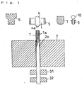
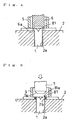
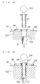
- Figs. 1 through 9 show the respective steps of manufacturing a rotary brush by this invention's manufacturing method.
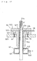
- Fig. 1 shows the principal parts of a manufacturing device for carrying out this method. That is, this device is equipped with a pedestal 2 having an insert hole 2a for passing through a wire group 1, an upper/lower pair of first and second chucks 31 and 32 disposed in a vertically movable manner at the lower side of the pedestal for grasping and releasing the wire group 1, a cone 4 disposed above the insert hole 2a of the pedestal 2 to be inserted into the center of the inserted upper side of the wire group 1, which is projected upward by a specified amount from the insert hole 2a of the pedestal 2 by the grasping and upward movement of the respective chucks 31 and 32, to push open the wire group 1 in radial directions, and a cylindrical pressing member 5 also disposed above the pedestal 2 for fixing the pushed-open wire group 1 above the pedestal 2.
- a welder 6, which, for example, is of an ultrasonic type and welds a center part of the wire group 1 with the wire group 1 being fixed on the pedestal 2, a cutting machine 7 for cutting the interior of the welded part of the wire group 1 while leaving at least a part thereof, and a pipe handling machine 10 for inserting a core pipe 9 into a brush unit 8 formed of the wire group 1 by means of the welder 6 and the cutting machine 7, insertingly holding a plurality of brush units and taking out each brush unit 8 along with the core pipe 9 to the exterior of the pedestal 2 after insertion and holding.
- the pipe handling machine 10 is arranged so that when the core pipe 9 is inserted in and made to hold a predetermined number of brush units 8, this core pipe 9 is removed and then another single core pipe 9 is successively taken out from an unillustrated holder for housing a plurality of core pipes 9 and set in the pipe handling machine 10.
- each component is moved to the position above the wire group 1 by means of a horizontal moving means to perform the required process.
- the pedestal may be moved in the horizontal direction instead.
- the wire group 1 formed by assembling together wires 1a made of a thermoplastic resin, such as nylon, etc. in a bundle is grasped by the abovementioned first and second chucks 31 and 32, and by the upward movement of these chucks, the wire group 1 is held in a state in which it is projected upward by a specified amount from the insert hole 2a of the pedestal 2.
- the movements of these chucks 31 and 32 shall be described in detail later.
- the pressing member 5 has, for example, a cylindrical lower end face.
- the pressing member 5 presses a somewhat outer side of a central part of the wire group 1 that has been pushed open in radial directions.
- a spatial allowance for the entry of the tip of the welder is left at the inner side of the pressing member 5 so as to enable the insertion of the welder 6 after the cone 4 with a downward-directed conical protrusion being retreated in the state in which the pressing member 5 is pressing.
- the pressing member 5 sandwiches the wire group against the pedestal 2 and holds the wire group firmly so that it will not move.
- the abovementioned cone 4 retreats with the pushed-open wire group 1 being fixed on the pedestal 2 by the pressing member 5.
- the abovementioned welder 6 is moved to the position directly above the center of the wire group 1 and is inserted into the interior of the pressing member 5, and the central part of the pushed-open wire group 1 is welded in annular shape by the tip of the welder 6.
- welder a type that uses ultrasonic waves is used favorably, and this welder is equipped with a circular welding part 6a at its tip and pressingly welds the wire group 1 pushed open between the pressing member 5 and the pedestal 2 at the inner side of the pressing member.
- the inner circumference of the welded part 81 formed by welder 6 is preferably matched with the upper rim 2b of the insert hole 2a.
- the abovementioned welder 6 is retreated, and subsequently the abovementioned cutting machine 7 is moved to the position directly above the center of the wire group 1 and is inserted into the interior of pressing member 5, and by the tip of the cutting machine 7, an inner circumferential part 81a of the welded part 81 of the pushed-open wire group 1 is cut in circular form.
- the outer peripheral surface of the tip is formed to a truncated conical surface 7a inclined with respect to the central line, and the wire group is sandwiched and cut between this truncated conical surface 7a and the upper rim 2b of the circular insert hole 2a of the pedestal 2.
- the truncated conical surface 7a and the upper rim 2b of the insert hole 2a are formed of a material having the required hardness, etc., or are subject to a prescribed heat treatment to enable the cutting process to be repeated a larger number of times.
- a sheet-like brush unit 8 having a hub (welded part) 81 at the center thereof and having a plurality of bristles (wires) 82 projecting in radial directions from the hub 81 is thereby formed (see Fig. 6).
- the above-described welding of the central part of the wire group 1 by the welder 6 and the cutting of the inner part of the welded part by the cutting machine 7 may be carried out in reverse order. That is, the center portion of the wire group 1 may be cut in circular form by the cutting machine 7 and then the circumference thereof may be welded in annular shape by the welder 6.
- the wire group 1 is thus welded in annular shape with it being fixed on the pedestal and the inner side of the welded part is cut with the wire group likewise being fixed on the pedestal, the thickness of the welded part 81 is finished uniformly.
- the pipe handling machine 10 in the state in which it holds a core pipe 9, is moved to the position immediately above the center of the hub 81 of the brush unit 8 that has been made on the pedestal 2.
- the core pipe 9 is inserted via hub 81 into the insert hole 2a of the pedestal 2 and the core pipe 9 is thereby made to insertingly hold brush unit 8.
- the pipe handling machine 10 rises, thereby taking out the brush unit 8 along with the core pipe 9 to the exterior of the pedestal 2, and the pipe handling machine 10 then waits at a predetermined upper position.
- the second chuck 32 is opened and moved downward with the first chuck 31 being closed. After being moved downward by a predetermined amount, the second chuck is closed so as to grasp the wire group 1 again.
- the first chuck 31 is thereafter opened and the second chuck 32 is raised to a predetermined position. After the rise to the predetermined position, the first chuck 31 is closed.
- both chucks 31 and 32 are raised so that the wire group 1 grasped by these chucks is held while projecting upwards by a specified amount from the insert hole 2a of the pedestal 2.
- the wire group 1 can thereby be held in a manner whereby the specified amount thereof is projected upwards from the insert hole 2a of the pedestal 2 without causing the dropping of the wire group 1 downwards.
- the core pipe 9 is made to insertingly hold brush units 8 successively as shown in Fig. 8. Then after the core pipe 9 is made to insertingly hold a predetermined number of the brush units 8, the core pipe 9 and the brush units 8 are removed from the pipe handling machine 10, and a new core pipe 9 is taken out from the holder and set in the pipe handling machine 10. After being taken out from the pipe handling machine 10, the brush units 8 are fixed to the core pipe 9 as shown in Fig. 9.
- a core pipe 9 made of nylon or other thermoplastic resin and having a collar 91 formed integrally at one end in the length direction and an annular receiving groove 92 formed at the other end side, is used, and is inserted into brush units 8 successively from the receiving groove 92 side with the collar part 91 being positioned upward.
- a cylindrical lid 94 made of the same material as the above-described core pipe 9 and having a protrusion 93 to be inserted in the abovementioned receiving groove 92, is used and the protrusion 93 thereof is inserted into the receiving groove 92, and the predetermined number of brush units 8 are fixed onto the core pipe 9 by joining the lid 94 to the core pipe 9 by a sealing means using ultrasonic waves, etc., to prepare the rotary brush 11.
- Fig. 10 is a plan view of a device used for post-processing of the rotary brush 11 and Fig. 11 is a side view showing the principal parts of the same device in an exploded manner.
- a plurality of pins 14 insertable into the core pipes 9 of the above-described rotary brushes 11 are protruded from the upper outer circumferential parts of a turntable 13 driven to rotate in the direction of the arrow R by a motor 12.
- a rubber roller 15 At outer peripheral positions of the turntable 13 are positioned a rubber roller 15, which contacts a rotary brush 11 in which a pin 14 is inserted, and a clipper or other cutter 16.
- the tips of bristles 82 of the rotary brush 11 are trimmed to uniform length by the abovementioned cutter 16.
- a removal prevention member 18 for the rotary brush 11 is positioned above the finishing machines 17, and at a position of the turntable 13 rearward the finishing machines 17 in the direction of rotation is positioned a take-out machine 19, which takes out the finished rotary brush 11 from the pin 14.
- 20 denotes a sensor that checks the setting of a rotary brush 11 on a pin 14 and drives finishing machines 17, and 21 denotes a sensor for checking the taking out of a rotary brush 11 from a pin 14 by the take-out machine 19.
- L indicates the range along the turntable 13 in which rotary brushes 11 are set on pins 14.
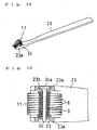
- Fig. 12 is a perspective view showing a roll toothbrush 22 fitted with a rotary brush 11 that has been obtained as described above.
- This toothbrush 22 is formed by the abovementioned rotary brush 11 being supported rotatably via a supporting shaft 24 at one end in the length direction of a handle member 23.
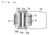
- Fig. 13 and Fig. 14 are sectional views for describing the states in which a rotary brush 11, which has been obtained as described above, is set in a handle member 23 of a roll toothbrush 22.
- the rotary brush 11 is interposed between supporting pieces 23a formed at both sides of one end in the length direction of the handle member 23, and then the supporting shaft 24 having a head part 24a is inserted from one supporting piece 23a to the other supporting piece 23a through the core pipe 9 of the rotary brush 11.
- the other end side of the supporting shaft 24 is thereafter squashed so that the rotary brush 11 is rotatably supported in the handle member 23 via the supporting shaft 24.
- concaves 23b are formed in the respective supporting pieces 23a of the abovementioned handle member 23, and the head part 24a of the abovementioned supporting shaft 24 and the squashed part 24b at the other side are positioned in these concaves.
- the head part 24a of the abovementioned supporting shaft 24 is preferably made noncircular in shape and the abovementioned concaves 23b of the supporting piece 23a that receives it is also preferably made noncircular in shape, and by arranging thus, the rotary brush 11 can be made to rotate smoothly about the supporting shaft 24.
- Fig. 15 is a partially cutaway front view showing this invention's device for manufacturing a brush unit for a rotary brush to be used in a rotary toothbrush.
- This device is equipped with a pedestal 52 having an insert hole 52a for passing through a wire group 51 formed by assembling together wires 51a, for example, of nylon or other thermoplastic resin in a bundle, and a chuck 53 disposed in a vertically movable manner at the lower side of the pedestal 52 for grasping and releasing the wire group 51.
- a nozzle 54 for blowing air into a central part of the inserted upper end of the wire group 51, which is projected by a specified amount above the insert hole 52a of the pedestal 52 by the grasping and upward movement of the abovementioned chuck 53, to open up the wire group 51 in radial directions
- a pressing member 55 for fixing the opened-up wire group 51 onto the pedestal 52
- a welder 56 which is, for example, of an ultrasonic type and welds a center part of the wire group 51 with the wire group 51 being fixed on the pedestal 52 by the pressing member 55
- a cut-off means 57 for cutting off a central part of the welded part of the wire group 51 while leaving at least a part of the welded part.
- the abovementioned chuck 53 is equipped with a casing 531 having an air supply/discharge pipe 530 connected to a compressor 540, and a cylindrical resilient member 532 positioned in the interior of the casing, which is made of rubber, etc., and has collars provided at its upper and lower sides.
- a casing 531 having an air supply/discharge pipe 530 connected to a compressor 540
- a cylindrical resilient member 532 positioned in the interior of the casing, which is made of rubber, etc., and has collars provided at its upper and lower sides.
- the wire group 51 is opened up in radial directions by the air from the nozzle 54. After this opened-up wire group 51 is fixed onto the pedestal 52 by the abovementioned pressing member 55, the chuck 53 releases the wire group 51 and then returns to the original downward position. With this arrangement, the structure can be simplified since just one chuck 53 suffices.
- the work operation of making the wire group 51 be projected outward from the insert hole 52a of the pedestal 52 can be performed in a simple and yet definite manner.
- the abovementioned nozzle 54 has an air passage 541,which is connected to the abovementioned compressor 540, formed in the central interior thereof. By the blowing of air from this air passage 541 onto the central part of the projected end of the abovementioned wire group 51, the wire group 51 is opened up in radial directions.
- the abovementioned cut-off means 57 is formed integrally on an outer peripheral part of this nozzle 54. That is, a cylindrical protrusion 542 is formed at the front end side of the nozzle 54 and by hardening, etc., a front outer peripheral thereof, the front outer peripheral part of the protrusion 542 is made into the abovementioned cut-off means 57.
- the nozzle 54 having the abovementioned cut-off means 57 and the welder 56 are mounted to a first frame 571, which extends in the transverse direction.
- This first frame 571 is supported in a manner enabling movement to the left and right in a transverse groove 572a formed in a second frame 572 that extends in the same direction, and the abovementioned second frame 572 is supported in a manner enabling upward and downward movement in a vertical groove 573a formed in a third frame 573 that extends in the vertical direction, to enable the abovementioned nozzle 54 and welder 56 to move in the two-dimensional directions of left, right, up, and down.
- This arrangement also simplifies the arrangement of the device as a whole and also simplifies the moving/operation system for the abovementioned nozzle 54 and the welder 56.
- the abovementioned nozzle 54 and the cut-off means 57 are thus arranged as a single block as described above, and since it suffices to move and operate just the two components of this block and the welder 56 in the two-dimensional directions between left and right limit positions 572b and 572c, the moving/operation system therefor can be simplified.
- Fig. 16 is a perspective view showing the principal parts of the manufacturing device and shows the part of the abovementioned pedestal 52 in an exploded manner.
- This pedestal 52 comprises a disk-like first member 521 joined onto a fixed base 520 (see Fig. 15) by means of a plurality of bolts B1 and a disk-like second member 522 joined above the first member 521 by means of a plurality of bolts B2, and the insertion hole 52a for passing through the abovementioned wire group 51 is formed in central parts of these first and second members 521 and 522.
- a slide groove 523 which passes through a central part of the first member 521 in a through-going manner in the diameter direction, and in this slide groove 523 is mounted a slide blade 58, which cuts and removes a remaining welded part 51a (see Fig. 23) of the wire group 51 that has been cut by the cut-off means 57 formed on the above-described nozzle 54.
- This slide blade 58 has the inclining face 580, which extends rearward from the blade edge in an upwardly inclining manner, formed at its tip, and by this inclining face 580, a force in the direction of extracting the remaining welded part 51b (see Fig. 23) of the wire group 51 from the insert hole 52a of the pedestal 52 is applied.
- the insert hole 52a formed in the abovementioned first member 521 has an inwardly directed collar part 5211 formed at the upper end, and below this, the diameter is made large in comparison to the inner diameter of the inwardly directed collar part 5211.
- a cylindrical member 533 which is protruded upward from a central part of the abovementioned chuck 53, is inserted in a manner enabling upward and downward movement, and a coil spring 534 is interposed between this cylindrical member 533 and an upper end part of the abovementioned enlarged diameter part 52b.
- the inner diameters of the abovementioned cylindrical member 533 and the coil spring 534 are made substantially the same as that of the abovementioned insert hole 52a.
- the wire group 51 is arranged to be inserted from the interiors of the cylindrical member 533 and coil spring 534 to the insert hole 52a in the above-described first and second members 521 and 522.
- the wire group 51 when the wire group 51 is projected upwards from the insert hole 52a by means of the above-described chuck 53, the wire group 51 can be fed smoothly without becoming caught in the insert hole 52a.
- the wire group 51 is thus projected upwards from the insert hole 52a, opened up in radial directions by the air from the nozzle 54, and welded by the welder 56 while being fixed onto the pedestal 52 by the pressing member 55. Thereafter, the central part of the wire group 51 is cut off by the cut-off means 57 while leaving at least a part of the welded part, and in this process, the cut-off part is pushed inside the insert hole 52a (see Fig. 22).
- the length of the coil spring 534 is made longer than the vertical length of the enlarged diameter part when the cylindrical member 533 is lowered the most. The expansion of the wires can thereby be prevented at any position when the cylindrical member moves up and down.
- the abovementioned pressing member 55 comprises a cylindrical main pressing member body 551 having at its center an insert hole 551a through which the above-described nozzle 54 and the welder 56 are inserted, and a supporting member 552, which supports the main pressing member body 551 with a part of the main pressing member body 551 being projected downwards.
- This supporting member 552 is connected to an unillustrated vertical movement mechanism, and by this vertical movement mechanism, the entirety of the pressing member 55 is moved in the up/down directions along a central line that passes through the center of the insert hole 52a of the above-described pedestal 52.
- Figs. 17 through 23 show the respective steps for manufacturing a brush unit for rotary brush by this invention' s manufacturing method.
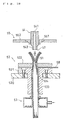
- the first frame 571 of Fig. 15 then moves transversely along the groove 572a of the second frame 572, and when the nozzle 54, which is mounted to the first frame 571, reaches a position immediately above the insert hole 52a of the pedestal 52, the first frame 571 moves downwards along the groove 573a of the third frame 573 while accompanying the second frame 572, and as shown in Fig. 18 and Fig. 19, the abovementioned nozzle 54 is thereby inserted inside the insert hole 551a of the main pressing member body 551 of the pressing member 55.
- Air from the air passage 541 of the abovementioned nozzle 54 is blown onto the center of the upper end of the wire group 51 projected upwards from the abovementioned insert hole 52a of the pedestal 52, thereby causing the wire group 51 to open up in radial directions (second step).
- the abovementioned pressing member 55 moves downwards.
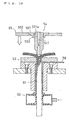
- the wire group 51 is thereby fixed onto the pedestal 52 in the opened-up state by the pressing member 55 as shown in Fig. 20.
- the abovementioned first frame 571 moves upward along the groove 573a of the third frame 573 and the abovementioned nozzle 54 is retreated upwards.
- the abovementioned chuck 53 is at the upwardly-moved position. As shown in Fig.
- the abovementioned first frame 571 of Fig. 15 moves in the transverse direction along the groove 572a of the second frame 572 until it contacts the right side limit position, and the abovementioned nozzle 54 is moved away from the pedestal 52 to the hypothetical line position shown in Fig. 15, and the welder 56 is moved to a position immediately above the wire group 51 on the pedestal 52.
- the first frame 571 moves downward again along the groove 573a of the third frame 573 while accompanying the second frame 572.
- the abovementioned welder 56 thus passes through the interior of the main pressing member body 551 of the pressing member 55 and descends to a position immediately above the center of the wire group 51 with the opened-up wire group 51 being fixed onto the pedestal 52 by the pressing member 55 as shown in Fig. 21, and a central part area of the opened-up wire group 51 is welded by the tip of the welder 56 (third step).
- Ahigh-frequency welder is used for welding, and a circular area slightly larger in diameter than that of the insert hole 52a is welded.
- the abovementioned first frame 571 moves upward so that the welder 56 is retreated upwards from the pedestal 52 and pressing member 55 and returned to its original position, and then moves transversely so that the abovementioned nozzle 54 is moved to a position immediately above the insert hole 52a of the pedestal 52.
- the second frame 572 moves downward along the groove 573a of the third frame 573 while accompanying the first frame 571.
- the tip of the abovementioned nozzle 54 is thereby passed through the insert hole 551a of the pressing body 55 and is inserted into a part of the insert hole 52a provided in the second member 522 of the pedestal 52.
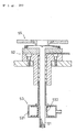
- a center part of the welded part of the opened-up wire group 51 is cut off by the cut-off means 57 formed at the tip of the abovementioned nozzle 54, and the upper end of the insert hole 52a as shown in Fig. 22 (fourth step).
- An annular welded part 591 is left at the center of the opened-up wire group 51.
- a sheet-form brush unit 59 having a hub (welded part) 591 at its center and having a plurality of bristles (wires) 592 projecting in radial directions from this hub 591 is thus formed on the abovementioned pedestal 52.
- This brush unit 59 is taken out to the exterior by a pipe handling machine 510 as shall be described later.
- the slide blade 58 advances along the slide groove 523 and cuts off a lower position of the cut-off part 51b as shown in Fig. 23.
- the slide blade 58 has the inclining face 580, which extends rearward from the blade edge in an upwardly inclining manner, formed at its tip, and a force in the direction of extracting the remaining welded part 51a of the wire group 51 from the insert hole 52a of the pedestal 52 is applied by this inclining face 580, even if the cut-off part 51b of the wire group 51 becomes attached to the insert hole 52a side, it can be pushed upward by the slide blade 58 to release the attached state.
- the wire group 51 is grasped by the resilient member 532 inside the abovementioned chuck 53 being expanded by air, the wire group 511 is moved upward from the insert hole 52a of the pedestal 52 by the rising of the chuck 53 in this state, and the cut-off part 51b is also moved upward and can thus be taken out to the exterior speedily.
- the wire group 51 that follows the cut-off part 51b can thus be inserted into the insert hole 52a of the pedestal 52, and the transition to the next work step can be performed speedily.
- the pipe handling machine 510 which is positioned in the vicinity of the abovementioned pedestal 52, is moved, while holding a core pipe 511, to a position immediately above the hub 591 of the brush unit 59 prepared on the pedestal 52 as shown in Fig. 24. Then as shown in Fig. 25, the core pipe 511 is inserted from the hub 591 into the insert hole 52a of the pedestal 52 by the descent of the abovementioned pipe handling machine 510, and the core pipe 511 is thus made to be inserted in and hold the brush unit 59.
- the abovementioned pipe handling machine 510 rises, thereby taking out the brush unit 59 along with the core pipe 511 to the exterior of the pedestal 52, and the pipe handling machine 510 then waits at a predetermined upper position. Thereafter, the work steps of Figs. 17 to 23 are repeated and the core pipe 511 is made to insertingly hold brush units 59 successively as shown in Fig. 26.
- the core pipe 511 is made to insertingly hold a predetermined number of the brush units 59
- the core pipe 511 and the brush units 59 are removed from the pipe handling machine 510, and a new core pipe 59 is taken out from a holder and set in the pipe handling machine 510.
- the brush units 59 are fixed to the core pipe 511 as shown in Fig. 27.
- a core pipe 511 made of nylon or other thermoplastic resin and having a collar 511a formed integrally at one end in the length direction and an annular receiving groove 511b formed at the other end side, is used. From the receiving groove 511b side, the core pipe is inserted successively into the brush units 59 with the collar part 511a being positioned upward.
- a cylindrical lid 511d made of the same material as the core pipe 511 and having a protrusion 511c insertable in the abovementioned receiving groove 511b, is used, and the protrusion 511c thereof is inserted into the receiving groove 511b, and the predetermined number of brush units 59 are fixed onto the core pipe 511 by joining the lid 511d to the core pipe 511 by a sealing means using ultrasonic waves, etc., to prepare a rotary brush 512.
- Fig. 28 is a plan view of a device used for post-processing of the rotary brush 512 and Fig. 29 is a side view showing the principal parts of the same device in an exploded manner.
- a plurality of pins 515 insertable into the core pipes 511 of the above-described rotary brushes 512 are protruded from the upper outer circumferential parts of a turntable 514 driven to rotate in the direction of the arrow by a motor 513.
- a rubber roller 516 At outer peripheral positions of the turntable 514 are positioned a rubber roller 516, which contacts a rotary brush 512 in which a pin 515 is inserted, and a clipper or other cutter 517.
- a removal prevention member 519 for the rotary brush 512 is positioned above the finishing machines 518, and at a position of the turntable 514 rearward the finishing machines 518 in the direction of rotation is positioned a take-out machine 520, which takes out the finished rotary brush 512 from the pin 515.
- S1 is a sensor that checks the setting of a rotary brush 512 on a pin 515 and drives finishing machines 518
- S2 is a sensor for checking the taking out of a rotary brush 512 from a pin 515 by the take-out machine 520.
- L indicates the range along the turntable 514 in which rotary brushes 512 are set on pins 515.
- Fig. 30 is a perspective view showing a roll toothbrush 560 fitted with a rotary brush 512 that has been obtained as described above.
- This toothbrush 560 is formed by the abovementioned rotary brush 512 being supported rotatably via a supporting shaft 562 at one end in the length direction of a handle member 561.
- Fig. 31 and Fig. 32 are sectional views for describing the states in which a rotary brush 512, which has been obtained as described above, is set in a handle member 561 of a roll toothbrush 560.
- the rotary brush 512 is interposed between supporting pieces 561a formed at both sides of one end in the length direction of the handle member 561 and then the supporting shaft 562 having a head part 562a is inserted from one supporting piece 561a to the other supporting piece 561a through the core pipe 511 of the rotary brush 512.
- the other end side of the supporting shaft 562 is thereafter squashed as shown in Fig. 32 so that the rotary brush 512 is rotatably supported in the handle member 561 via the supporting shaft 562.
- concaves 561b are formed in the respective supporting pieces 561a of the abovementioned handle member 561, and the head part 562a of the abovementioned supporting shaft 562 and the squashed part 562b at the other side are positioned in these concaves.
- the head part 562a of the abovementioned supporting shaft 562 is preferably made noncircular in shape and the abovementioned concaves 561b of the supporting piece 561a that receives it is also preferably made noncircular in shape, and by arranging thus, the rotary brush 512 can be made to rotate smoothly about the supporting shaft 562.
- this invention enables the manufacture of brush units of uniform thickness and enables manufacture without requiring an advanced degree of skill, mass production is enabled. Since the overlapping of the wires can be lessened, the brush units can be manufactured efficiently at high speed and the uniformalization and mass production of rotary toothbrushes are enabled.
Landscapes
- Engineering & Computer Science (AREA)
- Manufacturing & Machinery (AREA)
- Brushes (AREA)
Applications Claiming Priority (5)
| Application Number | Priority Date | Filing Date | Title |
|---|---|---|---|
| JP2002019212 | 2002-01-28 | ||
| JP2002019212A JP4037653B2 (ja) | 2002-01-28 | 2002-01-28 | 回転ブラシの製造方法と装置 |
| JP2002099172A JP3981290B2 (ja) | 2002-04-01 | 2002-04-01 | 回転歯ブラシの製造方法及び製造装置 |
| JP2002099172 | 2002-04-01 | ||
| PCT/JP2003/000801 WO2003063644A1 (fr) | 2002-01-28 | 2003-01-28 | Procede et dispositif de fabrication de brosse rotative et brosse a dents tournante |
Publications (2)
| Publication Number | Publication Date |
|---|---|
| EP1477084A1 true EP1477084A1 (fr) | 2004-11-17 |
| EP1477084A4 EP1477084A4 (fr) | 2005-04-20 |
Family
ID=27667431
Family Applications (1)
| Application Number | Title | Priority Date | Filing Date |
|---|---|---|---|
| EP03734864A Withdrawn EP1477084A4 (fr) | 2002-01-28 | 2003-01-28 | Procede et dispositif de fabrication de brosse rotative et brosse a dents tournante |
Country Status (7)
| Country | Link |
|---|---|
| US (1) | US7364241B2 (fr) |
| EP (1) | EP1477084A4 (fr) |
| KR (1) | KR100871302B1 (fr) |
| CN (1) | CN100366202C (fr) |
| CA (1) | CA2473455A1 (fr) |
| NZ (1) | NZ534059A (fr) |
| WO (1) | WO2003063644A1 (fr) |
Cited By (1)
| Publication number | Priority date | Publication date | Assignee | Title |
|---|---|---|---|---|
| EP2108280A4 (fr) * | 2008-02-13 | 2013-07-24 | Hiromi Fujita | Procédé pour produire un matériau en feuille pour brosse à dents rotative |
Families Citing this family (9)
| Publication number | Priority date | Publication date | Assignee | Title |
|---|---|---|---|---|
| WO2013010358A1 (fr) * | 2011-07-18 | 2013-01-24 | Wu Chengsheng | Brosse à dents à roues multiples |
| JP6042350B2 (ja) | 2012-01-27 | 2016-12-14 | 株式会社Stbヒグチ | 放射状羽根及びその製造方法 |
| JP2015167727A (ja) * | 2014-03-07 | 2015-09-28 | 槌屋ティスコ株式会社 | ロールブラシ及びその製造方法 |
| EP3135155A4 (fr) * | 2015-07-08 | 2017-07-19 | Kurun Co., Ltd. | Procédé et dispositif de fabrication d'unité de brosse pour brosse à dents rotative |
| CN105326576A (zh) * | 2015-11-18 | 2016-02-17 | 刘润宇 | 轴向旋转电动牙刷刷毛及其制造方法 |
| KR101904860B1 (ko) * | 2016-10-06 | 2018-10-08 | 신한다이아몬드공업 주식회사 | 다이아몬드 팁 절삭 휠용 부착물 제거 장치 |
| KR200485093Y1 (ko) | 2017-08-11 | 2017-11-28 | (주)미리 | 변기청소기 |
| US20220167587A1 (en) | 2019-06-12 | 2022-06-02 | Christopher C. Mogren | Pet grooming and skin care tool and methods of making and using the tool |
| CN112293932A (zh) * | 2020-09-24 | 2021-02-02 | 安徽瑞洁刷业有限公司 | 一种异形刷生产用压饼装置 |
Family Cites Families (3)
| Publication number | Priority date | Publication date | Assignee | Title |
|---|---|---|---|---|
| US2860921A (en) * | 1954-10-11 | 1958-11-18 | Pittsburgh Plate Glass Co | Method and apparatus for forming rotary brush |
| JP4040754B2 (ja) * | 1998-06-22 | 2008-01-30 | 秀夫 富山 | 歯ブラシおよびその製造方法 |
| JP3947378B2 (ja) * | 2001-10-03 | 2007-07-18 | 北村 昌廣 | 回転ブラシ用素材シートの製造方法および回転ブラシ用素材シート |
-
2003
- 2003-01-28 CA CA002473455A patent/CA2473455A1/fr not_active Abandoned
- 2003-01-28 CN CNB038027887A patent/CN100366202C/zh not_active Expired - Lifetime
- 2003-01-28 NZ NZ534059A patent/NZ534059A/en not_active IP Right Cessation
- 2003-01-28 US US10/501,963 patent/US7364241B2/en not_active Expired - Lifetime
- 2003-01-28 KR KR1020047010663A patent/KR100871302B1/ko not_active Expired - Fee Related
- 2003-01-28 EP EP03734864A patent/EP1477084A4/fr not_active Withdrawn
- 2003-01-28 WO PCT/JP2003/000801 patent/WO2003063644A1/fr not_active Ceased
Cited By (1)
| Publication number | Priority date | Publication date | Assignee | Title |
|---|---|---|---|---|
| EP2108280A4 (fr) * | 2008-02-13 | 2013-07-24 | Hiromi Fujita | Procédé pour produire un matériau en feuille pour brosse à dents rotative |
Also Published As
| Publication number | Publication date |
|---|---|
| US20050076460A1 (en) | 2005-04-14 |
| CN100366202C (zh) | 2008-02-06 |
| KR100871302B1 (ko) | 2008-12-01 |
| NZ534059A (en) | 2005-12-23 |
| CA2473455A1 (fr) | 2003-08-07 |
| HK1078749A1 (zh) | 2006-03-24 |
| US7364241B2 (en) | 2008-04-29 |
| EP1477084A4 (fr) | 2005-04-20 |
| KR20040077871A (ko) | 2004-09-07 |
| CN1622776A (zh) | 2005-06-01 |
| WO2003063644A1 (fr) | 2003-08-07 |
Similar Documents
| Publication | Publication Date | Title |
|---|---|---|
| US7364241B2 (en) | Method and device for manufacturing rotary brush and roll tooth brush | |
| US7992246B2 (en) | Radial vane for tooth brush, tooth brush using the same, and method and device for manufacturing the radial vane for the tooth brush | |
| US4869277A (en) | Brush head, a method and a machine for manufacturing thereof | |
| EP1409177B1 (fr) | Production de tubes a extremite fermee pour instruments chirurgicaux | |
| JP7219762B2 (ja) | 成形された房キャリアとベースプレートとを使用してブラシヘッドを製造する方法 | |
| US20150128368A1 (en) | Industrial brush, apparatus and method for making said industrial brush | |
| JP4037653B2 (ja) | 回転ブラシの製造方法と装置 | |
| JP3981290B2 (ja) | 回転歯ブラシの製造方法及び製造装置 | |
| JP4037739B2 (ja) | ロール歯ブラシ | |
| CN101422295B (zh) | 旋转刷卷绕装置以及旋转刷制造设备 | |
| JP4647928B2 (ja) | 回転ブラシのブラシ単体の製造装置 | |
| US10398219B2 (en) | Method and apparatus for manufacturing individual brush unit of rotary toothbrush | |
| JP4000355B2 (ja) | 歯ブラシ用放射状羽根及びこれを使用した歯ブラシ、並びにその歯ブラシ用放射状羽根の製造方法及び製造装置 | |
| WO2009101675A1 (fr) | Procédé pour produire un matériau en feuille pour brosse à dents rotative | |
| JP2003088424A (ja) | 回転ブラシの製造方法、回転ブラシ並びに歯ブラシ | |
| CN100556334C (zh) | 辐射状刷毛和牙刷及该辐射状刷毛的制造方法和制造装置 | |
| CN115056294B (zh) | 一种eps泡沫板打孔装置 | |
| HK1078749B (en) | Method and device for manufacturing rotary brush and roll tooth brush | |
| JPH09187538A (ja) | ゴルフクラブシャフトの切断面のバリ除去方法及びその装置 | |
| JP2007044105A (ja) | ボス付き一体型円筒状ブラシ及びその製造方法、並びにその円筒状ブラシを使用した360度型歯ブラシ | |
| HK1131527A (en) | Rotary brush, toothbrush, rotary brush winding machine and rotary brush production method | |
| JP2020534044A (ja) | ねじり止めされたブラシを加工する方法および装置 |
Legal Events
| Date | Code | Title | Description |
|---|---|---|---|
| PUAI | Public reference made under article 153(3) epc to a published international application that has entered the european phase |
Free format text: ORIGINAL CODE: 0009012 |
|
| 17P | Request for examination filed |
Effective date: 20040830 |
|
| AK | Designated contracting states |
Kind code of ref document: A1 Designated state(s): AT BE BG CH CY CZ DE DK EE ES FI FR GB GR HU IE IT LI LU MC NL PT SE SI SK TR |
|
| AX | Request for extension of the european patent |
Extension state: AL LT LV MK RO |
|
| A4 | Supplementary search report drawn up and despatched |
Effective date: 20050308 |
|
| GRAP | Despatch of communication of intention to grant a patent |
Free format text: ORIGINAL CODE: EPIDOSNIGR1 |
|
| STAA | Information on the status of an ep patent application or granted ep patent |
Free format text: STATUS: THE APPLICATION IS DEEMED TO BE WITHDRAWN |
|
| 18D | Application deemed to be withdrawn |
Effective date: 20110802 |