EP1477112B1 - Pulswellen-Untersuchungsgerät - Google Patents
Pulswellen-Untersuchungsgerät Download PDFInfo
- Publication number
- EP1477112B1 EP1477112B1 EP04076852A EP04076852A EP1477112B1 EP 1477112 B1 EP1477112 B1 EP 1477112B1 EP 04076852 A EP04076852 A EP 04076852A EP 04076852 A EP04076852 A EP 04076852A EP 1477112 B1 EP1477112 B1 EP 1477112B1
- Authority
- EP
- European Patent Office
- Prior art keywords
- pulse
- section
- body movement
- data
- waveform
- Prior art date
- Legal status (The legal status is an assumption and is not a legal conclusion. Google has not performed a legal analysis and makes no representation as to the accuracy of the status listed.)
- Expired - Lifetime
Links
- 230000033001 locomotion Effects 0.000 claims description 185
- 230000009466 transformation Effects 0.000 claims description 86
- 230000008859 change Effects 0.000 claims description 42
- 238000012935 Averaging Methods 0.000 claims description 2
- 230000036772 blood pressure Effects 0.000 description 159
- 230000004872 arterial blood pressure Effects 0.000 description 76
- 210000004369 blood Anatomy 0.000 description 52
- 239000008280 blood Substances 0.000 description 52
- 230000035487 diastolic blood pressure Effects 0.000 description 48
- 230000009471 action Effects 0.000 description 40
- 238000010586 diagram Methods 0.000 description 30
- 230000035485 pulse pressure Effects 0.000 description 27
- 230000006870 function Effects 0.000 description 22
- 230000000144 pharmacologic effect Effects 0.000 description 21
- 230000015654 memory Effects 0.000 description 20
- 230000035488 systolic blood pressure Effects 0.000 description 18
- 210000000707 wrist Anatomy 0.000 description 17
- 238000003745 diagnosis Methods 0.000 description 14
- 239000003814 drug Substances 0.000 description 14
- 238000005311 autocorrelation function Methods 0.000 description 12
- 210000004204 blood vessel Anatomy 0.000 description 12
- 239000004973 liquid crystal related substance Substances 0.000 description 12
- 238000000034 method Methods 0.000 description 12
- 238000007493 shaping process Methods 0.000 description 10
- 208000001953 Hypotension Diseases 0.000 description 9
- 238000004364 calculation method Methods 0.000 description 9
- 238000001514 detection method Methods 0.000 description 9
- 210000001519 tissue Anatomy 0.000 description 9
- 210000001367 artery Anatomy 0.000 description 8
- 230000008602 contraction Effects 0.000 description 8
- 230000000694 effects Effects 0.000 description 8
- 230000004048 modification Effects 0.000 description 8
- 238000012986 modification Methods 0.000 description 8
- 210000002321 radial artery Anatomy 0.000 description 8
- 230000001360 synchronised effect Effects 0.000 description 8
- 238000006243 chemical reaction Methods 0.000 description 7
- 230000002861 ventricular Effects 0.000 description 7
- 238000010521 absorption reaction Methods 0.000 description 6
- 206010020772 Hypertension Diseases 0.000 description 5
- 230000017531 blood circulation Effects 0.000 description 5
- 208000021822 hypotensive Diseases 0.000 description 5
- 230000001077 hypotensive effect Effects 0.000 description 5
- 230000010349 pulsation Effects 0.000 description 5
- 238000012360 testing method Methods 0.000 description 5
- 208000018672 Dilatation Diseases 0.000 description 4
- 102000001554 Hemoglobins Human genes 0.000 description 4
- 108010054147 Hemoglobins Proteins 0.000 description 4
- 230000001133 acceleration Effects 0.000 description 4
- 210000000709 aorta Anatomy 0.000 description 4
- 210000001765 aortic valve Anatomy 0.000 description 4
- 210000001715 carotid artery Anatomy 0.000 description 4
- 230000004217 heart function Effects 0.000 description 4
- 230000036543 hypotension Effects 0.000 description 4
- 238000005259 measurement Methods 0.000 description 4
- 239000002304 perfume Substances 0.000 description 4
- 238000006467 substitution reaction Methods 0.000 description 4
- 230000001276 controlling effect Effects 0.000 description 3
- 238000012937 correction Methods 0.000 description 3
- 229940079593 drug Drugs 0.000 description 3
- 230000001788 irregular Effects 0.000 description 3
- 238000010606 normalization Methods 0.000 description 3
- 229940124595 oriental medicine Drugs 0.000 description 3
- 230000010355 oscillation Effects 0.000 description 3
- 230000000737 periodic effect Effects 0.000 description 3
- 230000008569 process Effects 0.000 description 3
- 238000001228 spectrum Methods 0.000 description 3
- GYHNNYVSQQEPJS-UHFFFAOYSA-N Gallium Chemical compound [Ga] GYHNNYVSQQEPJS-UHFFFAOYSA-N 0.000 description 2
- 230000005856 abnormality Effects 0.000 description 2
- 239000002390 adhesive tape Substances 0.000 description 2
- UCTWMZQNUQWSLP-UHFFFAOYSA-N adrenaline Chemical compound CNCC(O)C1=CC=C(O)C(O)=C1 UCTWMZQNUQWSLP-UHFFFAOYSA-N 0.000 description 2
- 229940030600 antihypertensive agent Drugs 0.000 description 2
- 239000002220 antihypertensive agent Substances 0.000 description 2
- 229910052785 arsenic Inorganic materials 0.000 description 2
- 230000001174 ascending effect Effects 0.000 description 2
- 230000000747 cardiac effect Effects 0.000 description 2
- 230000007423 decrease Effects 0.000 description 2
- 201000010099 disease Diseases 0.000 description 2
- 208000037265 diseases, disorders, signs and symptoms Diseases 0.000 description 2
- 210000000624 ear auricle Anatomy 0.000 description 2
- 230000008030 elimination Effects 0.000 description 2
- 238000003379 elimination reaction Methods 0.000 description 2
- 238000002474 experimental method Methods 0.000 description 2
- 238000000605 extraction Methods 0.000 description 2
- 229910052733 gallium Inorganic materials 0.000 description 2
- 230000036449 good health Effects 0.000 description 2
- 230000001771 impaired effect Effects 0.000 description 2
- 210000004185 liver Anatomy 0.000 description 2
- 230000007246 mechanism Effects 0.000 description 2
- 210000004165 myocardium Anatomy 0.000 description 2
- 210000005259 peripheral blood Anatomy 0.000 description 2
- 239000011886 peripheral blood Substances 0.000 description 2
- 238000011160 research Methods 0.000 description 2
- 230000033764 rhythmic process Effects 0.000 description 2
- 230000000638 stimulation Effects 0.000 description 2
- 230000016776 visual perception Effects 0.000 description 2
- 206010006187 Breast cancer Diseases 0.000 description 1
- 229910001218 Gallium arsenide Inorganic materials 0.000 description 1
- 229910000530 Gallium indium arsenide Inorganic materials 0.000 description 1
- 206010061218 Inflammation Diseases 0.000 description 1
- -1 adrenaline Chemical class 0.000 description 1
- 230000032683 aging Effects 0.000 description 1
- QVGXLLKOCUKJST-UHFFFAOYSA-N atomic oxygen Chemical compound [O] QVGXLLKOCUKJST-UHFFFAOYSA-N 0.000 description 1
- 230000008901 benefit Effects 0.000 description 1
- 230000036760 body temperature Effects 0.000 description 1
- 210000000481 breast Anatomy 0.000 description 1
- 150000003943 catecholamines Chemical class 0.000 description 1
- 230000000295 complement effect Effects 0.000 description 1
- 238000013480 data collection Methods 0.000 description 1
- 230000003247 decreasing effect Effects 0.000 description 1
- 230000001419 dependent effect Effects 0.000 description 1
- 230000006866 deterioration Effects 0.000 description 1
- 230000004069 differentiation Effects 0.000 description 1
- 238000000295 emission spectrum Methods 0.000 description 1
- 210000001105 femoral artery Anatomy 0.000 description 1
- 210000000245 forearm Anatomy 0.000 description 1
- 239000003205 fragrance Substances 0.000 description 1
- 208000016354 hearing loss disease Diseases 0.000 description 1
- 210000001624 hip Anatomy 0.000 description 1
- 210000004394 hip joint Anatomy 0.000 description 1
- 229910052738 indium Inorganic materials 0.000 description 1
- APFVFJFRJDLVQX-UHFFFAOYSA-N indium atom Chemical compound [In] APFVFJFRJDLVQX-UHFFFAOYSA-N 0.000 description 1
- 230000004054 inflammatory process Effects 0.000 description 1
- 230000000968 intestinal effect Effects 0.000 description 1
- 210000003734 kidney Anatomy 0.000 description 1
- WABPQHHGFIMREM-UHFFFAOYSA-N lead(0) Chemical compound [Pb] WABPQHHGFIMREM-UHFFFAOYSA-N 0.000 description 1
- 210000000653 nervous system Anatomy 0.000 description 1
- 229910052760 oxygen Inorganic materials 0.000 description 1
- 239000001301 oxygen Substances 0.000 description 1
- 230000002093 peripheral effect Effects 0.000 description 1
- 239000004033 plastic Substances 0.000 description 1
- 230000000644 propagated effect Effects 0.000 description 1
- 230000000541 pulsatile effect Effects 0.000 description 1
- 238000005086 pumping Methods 0.000 description 1
- 230000009467 reduction Effects 0.000 description 1
- 230000011514 reflex Effects 0.000 description 1
- 230000001105 regulatory effect Effects 0.000 description 1
- 230000000241 respiratory effect Effects 0.000 description 1
- 230000000284 resting effect Effects 0.000 description 1
- 230000035945 sensitivity Effects 0.000 description 1
- 230000008786 sensory perception of smell Effects 0.000 description 1
- 229910001285 shape-memory alloy Inorganic materials 0.000 description 1
- 210000002027 skeletal muscle Anatomy 0.000 description 1
- 238000010183 spectrum analysis Methods 0.000 description 1
- 238000005309 stochastic process Methods 0.000 description 1
- 210000002784 stomach Anatomy 0.000 description 1
- 239000000758 substrate Substances 0.000 description 1
- 229940124594 traditional oriental medicine Drugs 0.000 description 1
- 238000000844 transformation Methods 0.000 description 1
- 238000013519 translation Methods 0.000 description 1
Images
















Classifications
-
- A—HUMAN NECESSITIES
- A61—MEDICAL OR VETERINARY SCIENCE; HYGIENE
- A61B—DIAGNOSIS; SURGERY; IDENTIFICATION
- A61B5/00—Measuring for diagnostic purposes; Identification of persons
- A61B5/48—Other medical applications
- A61B5/4854—Diagnosis based on concepts of alternative medicine, e.g. homeopathy or non-orthodox
-
- A—HUMAN NECESSITIES
- A61—MEDICAL OR VETERINARY SCIENCE; HYGIENE
- A61B—DIAGNOSIS; SURGERY; IDENTIFICATION
- A61B5/00—Measuring for diagnostic purposes; Identification of persons
- A61B5/02—Detecting, measuring or recording for evaluating the cardiovascular system, e.g. pulse, heart rate, blood pressure or blood flow
- A61B5/021—Measuring pressure in heart or blood vessels
-
- A—HUMAN NECESSITIES
- A61—MEDICAL OR VETERINARY SCIENCE; HYGIENE
- A61B—DIAGNOSIS; SURGERY; IDENTIFICATION
- A61B5/00—Measuring for diagnostic purposes; Identification of persons
- A61B5/02—Detecting, measuring or recording for evaluating the cardiovascular system, e.g. pulse, heart rate, blood pressure or blood flow
- A61B5/021—Measuring pressure in heart or blood vessels
- A61B5/02108—Measuring pressure in heart or blood vessels from analysis of pulse wave characteristics
- A61B5/02116—Measuring pressure in heart or blood vessels from analysis of pulse wave characteristics of pulse wave amplitude
-
- A—HUMAN NECESSITIES
- A61—MEDICAL OR VETERINARY SCIENCE; HYGIENE
- A61B—DIAGNOSIS; SURGERY; IDENTIFICATION
- A61B5/00—Measuring for diagnostic purposes; Identification of persons
- A61B5/68—Arrangements of detecting, measuring or recording means, e.g. sensors, in relation to patient
- A61B5/6801—Arrangements of detecting, measuring or recording means, e.g. sensors, in relation to patient specially adapted to be attached to or worn on the body surface
- A61B5/6802—Sensor mounted on worn items
- A61B5/681—Wristwatch-type devices
-
- A—HUMAN NECESSITIES
- A61—MEDICAL OR VETERINARY SCIENCE; HYGIENE
- A61B—DIAGNOSIS; SURGERY; IDENTIFICATION
- A61B5/00—Measuring for diagnostic purposes; Identification of persons
- A61B5/68—Arrangements of detecting, measuring or recording means, e.g. sensors, in relation to patient
- A61B5/6801—Arrangements of detecting, measuring or recording means, e.g. sensors, in relation to patient specially adapted to be attached to or worn on the body surface
- A61B5/6813—Specially adapted to be attached to a specific body part
- A61B5/6814—Head
-
- A—HUMAN NECESSITIES
- A61—MEDICAL OR VETERINARY SCIENCE; HYGIENE
- A61B—DIAGNOSIS; SURGERY; IDENTIFICATION
- A61B5/00—Measuring for diagnostic purposes; Identification of persons
- A61B5/68—Arrangements of detecting, measuring or recording means, e.g. sensors, in relation to patient
- A61B5/6801—Arrangements of detecting, measuring or recording means, e.g. sensors, in relation to patient specially adapted to be attached to or worn on the body surface
- A61B5/6813—Specially adapted to be attached to a specific body part
- A61B5/6814—Head
- A61B5/6815—Ear
- A61B5/6816—Ear lobe
-
- A—HUMAN NECESSITIES
- A61—MEDICAL OR VETERINARY SCIENCE; HYGIENE
- A61B—DIAGNOSIS; SURGERY; IDENTIFICATION
- A61B5/00—Measuring for diagnostic purposes; Identification of persons
- A61B5/68—Arrangements of detecting, measuring or recording means, e.g. sensors, in relation to patient
- A61B5/6801—Arrangements of detecting, measuring or recording means, e.g. sensors, in relation to patient specially adapted to be attached to or worn on the body surface
- A61B5/6813—Specially adapted to be attached to a specific body part
- A61B5/6822—Neck
-
- A—HUMAN NECESSITIES
- A61—MEDICAL OR VETERINARY SCIENCE; HYGIENE
- A61B—DIAGNOSIS; SURGERY; IDENTIFICATION
- A61B5/00—Measuring for diagnostic purposes; Identification of persons
- A61B5/68—Arrangements of detecting, measuring or recording means, e.g. sensors, in relation to patient
- A61B5/6801—Arrangements of detecting, measuring or recording means, e.g. sensors, in relation to patient specially adapted to be attached to or worn on the body surface
- A61B5/6813—Specially adapted to be attached to a specific body part
- A61B5/6825—Hand
- A61B5/6826—Finger
-
- A—HUMAN NECESSITIES
- A61—MEDICAL OR VETERINARY SCIENCE; HYGIENE
- A61B—DIAGNOSIS; SURGERY; IDENTIFICATION
- A61B5/00—Measuring for diagnostic purposes; Identification of persons
- A61B5/68—Arrangements of detecting, measuring or recording means, e.g. sensors, in relation to patient
- A61B5/6801—Arrangements of detecting, measuring or recording means, e.g. sensors, in relation to patient specially adapted to be attached to or worn on the body surface
- A61B5/6813—Specially adapted to be attached to a specific body part
- A61B5/6828—Leg
-
- A—HUMAN NECESSITIES
- A61—MEDICAL OR VETERINARY SCIENCE; HYGIENE
- A61B—DIAGNOSIS; SURGERY; IDENTIFICATION
- A61B5/00—Measuring for diagnostic purposes; Identification of persons
- A61B5/68—Arrangements of detecting, measuring or recording means, e.g. sensors, in relation to patient
- A61B5/6801—Arrangements of detecting, measuring or recording means, e.g. sensors, in relation to patient specially adapted to be attached to or worn on the body surface
- A61B5/683—Means for maintaining contact with the body
- A61B5/6838—Clamps or clips
-
- A—HUMAN NECESSITIES
- A61—MEDICAL OR VETERINARY SCIENCE; HYGIENE
- A61B—DIAGNOSIS; SURGERY; IDENTIFICATION
- A61B5/00—Measuring for diagnostic purposes; Identification of persons
- A61B5/72—Signal processing specially adapted for physiological signals or for diagnostic purposes
- A61B5/7203—Signal processing specially adapted for physiological signals or for diagnostic purposes for noise prevention, reduction or removal
- A61B5/7207—Signal processing specially adapted for physiological signals or for diagnostic purposes for noise prevention, reduction or removal of noise induced by motion artifacts
- A61B5/721—Signal processing specially adapted for physiological signals or for diagnostic purposes for noise prevention, reduction or removal of noise induced by motion artifacts using a separate sensor to detect motion or using motion information derived from signals other than the physiological signal to be measured
-
- A—HUMAN NECESSITIES
- A61—MEDICAL OR VETERINARY SCIENCE; HYGIENE
- A61B—DIAGNOSIS; SURGERY; IDENTIFICATION
- A61B5/00—Measuring for diagnostic purposes; Identification of persons
- A61B5/72—Signal processing specially adapted for physiological signals or for diagnostic purposes
- A61B5/7235—Details of waveform analysis
- A61B5/7253—Details of waveform analysis characterised by using transforms
- A61B5/726—Details of waveform analysis characterised by using transforms using Wavelet transforms
-
- A—HUMAN NECESSITIES
- A61—MEDICAL OR VETERINARY SCIENCE; HYGIENE
- A61B—DIAGNOSIS; SURGERY; IDENTIFICATION
- A61B5/00—Measuring for diagnostic purposes; Identification of persons
- A61B5/103—Measuring devices for testing the shape, pattern, colour, size or movement of the body or parts thereof, for diagnostic purposes
- A61B5/11—Measuring movement of the entire body or parts thereof, e.g. head or hand tremor or mobility of a limb
-
- A—HUMAN NECESSITIES
- A61—MEDICAL OR VETERINARY SCIENCE; HYGIENE
- A61B—DIAGNOSIS; SURGERY; IDENTIFICATION
- A61B5/00—Measuring for diagnostic purposes; Identification of persons
- A61B5/72—Signal processing specially adapted for physiological signals or for diagnostic purposes
- A61B5/7235—Details of waveform analysis
- A61B5/7239—Details of waveform analysis using differentiation including higher order derivatives
-
- A—HUMAN NECESSITIES
- A61—MEDICAL OR VETERINARY SCIENCE; HYGIENE
- A61B—DIAGNOSIS; SURGERY; IDENTIFICATION
- A61B5/00—Measuring for diagnostic purposes; Identification of persons
- A61B5/72—Signal processing specially adapted for physiological signals or for diagnostic purposes
- A61B5/7235—Details of waveform analysis
- A61B5/7253—Details of waveform analysis characterised by using transforms
- A61B5/7257—Details of waveform analysis characterised by using transforms using Fourier transforms
Definitions
- the present invention relates to a pulse wave examination apparatus suitable for specifying the type of human pulse wave, a blood pressure monitor using the mean blood pressure and pulse pressure as its parameters and a pulse waveform monitor and a pharmacological action monitor which use a parameter related to a dicrotic notch part of an arterial pressure waveform.
- the pulse wave is usually defined as a wave of blood which is output from the heart and propagates through a blood vessel. For this reason, it is known that various types of medical information can be obtained by the detection of pulse wave and analysis of the detected pulse wave. With the progress of studies on the pulse wave, it has become clear that various types of information, not obtainable only from the blood pressure and the pulse rate, can be obtained by analyzing the pulse wave, collected from the human body, by various techniques, making a diagnosis possible on the basis of these types of information.
- the inventors of the present invention remarked the relation between the pulse waveform and its distortion rate in PCT/JP96/01254 (Title of the Invention: DIAGNOSTIC APPARATUS FOR DETECTING CONDITION OF LIVING BODY AND CONTROLLER) and made it possible to diagnose the living condition of a subject by detecting and treating the pulse waveform of the subject, calculating the distortion rate of the waveform and specifying the waveform from the distortion rate.
- FIGS. 45A to 45C are the charts showing representative pulse waveforms by this classification.
- the pulse waveform shown in Figure 45A is called a "Ping mai” which is the pulse condition of a normal man in good health.
- This "Ping mai” is characterized in that, as shown in the figure, the pulse is relaxed, and exhibits a constant rhythm without disruption.
- the pulse waveform shown in Figure 45B is called a "Hua mai” which is the pulse condition of a man who shows an abnormality in his blood stream condition.
- the waveform of a Hua mai exhibits a sharp, rapid rise, and then falls off immediately, the aortic dicrotic notch is deep and at the same time the subsequent peak is considerably higher than that of a Ping mai.
- diseases such as a mammary tumor, liver or kidney ailment, respiratory ailment, stomach or intestinal ailment or inflammation, or some other illness cause the movement of the blood to be very fluent and smooth, which causes this "Hua mai".
- the pulse waveform shown in Figure 45C is called a "Xuan mai” which is the pulse condition of a man whose blood vessel wall tension has increased.
- the Xuan mai is characterized in that its waveform rises steeply and remains at a high pressure state for a fixed period of time without an immediate drop.
- This "Xuan mai” is seen in diseases such as liver and gall ailments, dermatological ailments, high blood pressure, and pain ailments. It is believed that tension in the automatic nervous system causes the walls of the blood vessels to constrict, decreasing elasticity, so that the effect of the blood pulsation of the pumped blood is not readily expressed, causing this phenomenon.
- the ordinate and the abscissa in the graphs of Figures 45A to 45C show blood pressure (mmHg) and time (second) respectively.
- the distortion rate d is in a range between 0.98 and 1.22.
- the distortion rate d is in a range between 0.92 and 1.10.
- the distortion rate d is in a range between 0.73 and 0.94.
- the pulse condition can be judged to be a Hua mai or a Ping mai when the distortion rate d of the pulse waveform is in a range between 0.98 and 1.10. Also, the pulse condition can be judged to be a Ping mai or a Xuan mai when the distortion rate d of the pulse waveform is in a range between 0.92 and 0.94. It is therefore difficult to judge the pulse condition precisely by a conventional pulse wave examination apparatus.
- a blood pressure gauge measuring a maximum blood pressure and a minimum blood pressure and displaying these pressures is used in noninvasive detection of blood pressure.
- the mean blood pressure is an important parameter for knowing the condition of the blood pressure of an individual.
- the mean blood pressure cannot be obtained only by measurements of a maximum blood pressure and minimum blood pressure.
- a medical examination is carried out by examining the pulse waveform detected by the fingers when a medical examiner presses with an optimum pressing force against a distal position of the forearm from the arteria radialis, that is, a medical examination is conducted by detection of a variation with the pressing force, which variation is felt by the fingers of the medical examiner corresponding to a variation in blood pressure.
- the pulse waveform felt when a proper pressing force is applied to the arteria radialis is roughly divided into three categories, which are designated as a "Ping mai", “Hua mai” and “Xuan mai” respectively asaforementioned.
- the Ping mai is deliberate and mild and its rhythm is stable and reduced in turbulence.
- This Ping mai is a pulse image for a man in good health.
- the Hua mai is the type in which the flow of the pulse is felt to be very fluent and smooth, showing abnormality in the blood stream condition.
- the Xuan mai is felt to be a straight, tense and long pulse and is regarded to be due to tension or aging of a blood vessel wall.
- Such medical examination method is dependent upon the pulse waveform classified by the sense of the medical examiner posing problems with regard to its objectivity and reproducibility.
- the present invention has been conducted in the above situation and has an object of providing a pulse wave examination which can judge the pulse condition objectively and accurately.
- Another object of the present invention is to provide a blood pressure monitor which can indicate blood conditions in more detail than the information of a maximum and minimum blood pressure and can monitor the monitor parameters signifying blood pressure noninvasively.
- a further object of the present invention is to provide a pulse waveform monitor which can carry out an examination by the pulse waveform objectively and reproducibly.
- US Patent No. 5027641A discloses an oscillometric non-invasive blood pressure simulator, which enables the testing of oscillometers without the need for dismantling or otherwise disturbing the oscillometer.
- tests were carried out to collect waveforms of several users representative of what an oscillometric blood pressure monitor senses.
- the direct arterial pressure was recorded from the left radial artery and the aorta.
- the users were then catheterised and the stability of each pressure signal was verified.
- a test inflation cycle was then initialised and the oscillometer was used to verify the stability and quality of the two indirect pressure signals.
- the data was then analysed to identify the typical characteristics of the pulse waveform and oscillometric envelope of each user.
- the pulse waveform characteristics which were analysed were the width and duty cycle, rise time, fall time, energy, maximum and minimum slopes, and wave shape indexes.
- An indication of the general similarity of waveform shapes at different mean cuff pressures was obtained by computing the autocorrelation function (ACF) of the pulse waveform for a given user during a single data collection cycle.
- ACF autocorrelation function
- International Patent Publication No. 97124982A discloses a method and apparatus for the measurement of cardiac output.
- the arterial blood pressure of a user is monitored continuously.
- the output data from the monitor is amplified and smoothed to provide a continuous blood pressure waveform.
- the waveform is then subjected to non-linear transformation which corrects the variations of the characteristics of the arterial system with pressure.
- the corrected waveform is then subjected to autocorrelation in order to derive the pulsatility and heart rate of the corrected waveform.
- the nominal stroke volume is calculated from the pulsatility and the nominal cardiac output is obtained by multiplying the nominal stroke volume by the heart rate.
- a pulse wave examination apparatus according to a first embodiment will be described below.
- the heart ejects blood by repeated contractions and dilatations.
- the time of causing blood to flow from the heart by a contraction/dilatation in one cycle is called "ejection time”.
- the pulse rate which is the number of contractions of the heart per unit time
- a catecholamine e.g., adrenaline
- the product of the pulse rate and the output that is, the flow rate of blood (per unit time) ejected from the heart increases.
- the ejection time is short and the output is small.
- the rate of increase in the pulse rate exceeds the rate of decrease in the output, the product of the pulse rate and the output increases on the whole.
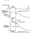
- a ventricular systole In the electrocardiogram shown in Figure 8, generally the period from the R point to the terminal point U of the T wave is said to be "a ventricular systole", which corresponds to the foregoing ejection time. The period from the U point to the next R point is said to be "a ventricular diastole". In the ventricular systole, a ventricular contraction does not take place uniformly but proceeds at a slow pace as it spreads from the outside to the inside.
- the waveform of the blood pressure at the proximal portion of an aorta has an upwardly convex form as shown in Figure 8 in the ventricular systole ranging from the opening to the closing of the aortic valve.
- the waveform of the blood pressure at the periphery (arteria radialis) corresponding to such a blood waveform at the proximal portion of an aorta, that is, the pulse waveform at the periphery is as shown in Figure 8.
- the reason why such a waveform is formed is considered that a first wave called an "ejection wave” occurs by the ejection of blood from the heart, a second wave called a "tidal wave” successively occurs due to a reflex at furcations of the blood vessel close to the heart, and a third wave called a "dicrotic wave” then occurs due to the occurrence of a dicrotic notch concomitant with the closing of the aortic valve.
- the range from the point at which the blood pressure reach a minimum to the dicrotic notch corresponds to the ventricular systole, and the range from the dicrotic notch to the point at which the blood pressure reaches a minimum in the next cycle corresponds to the ventricular diastole.
- the point corresponding to the opening of the aortic valve in the pulse waveform is the minimum minimal point of blood pressure.
- the point, specifically, the dicrotic notch, corresponding to the closing of the aortic valve is the third minimal point from the minimum minimal point viewing from time series and the second minimal point from the minimum minimal point viewing from the magnitude of the blood pressure.
- the waveform of the peripheral blood pressure shown in Figure 8 namely, the pulse waveform actually exhibits time delay with respect to the waveform of aortic blood pressure.
- this time delay is neglected for the sake of simplicity and these phases are made to be uniform.
- the pulse wave form detected at the peripheries of a subject is the so-called pattern of the pressure wave of blood which propagates through a closed system consisting of the heart as a pulsatile pump and the blood circulatory system as a conduit.
- the pulse wave form is regulated by the pumping function of the heart, namely, by the condition of a cardiac function.
- the pulse wave form is affected, for example, by the diameter of a blood vessel, contraction/dilatation of a blood vessel, and viscous resistance of blood.
- the pulse waveform is detected to analyze it, the condition of the cardiac function of the subject as well as the aortic condition of the subject can be evaluated. It may be understood that specialists in Oriental medicine diagnose a living condition by the features of pulsation.
- each of y 1 to y 5 denotes a relative value of blood pressure by setting the value of the blood pressure at a peak point P0 as a datum.
- the inventors of the present invention actually detected the pulse waves of 74 healthy adults between the ages of 22 and 46.
- the waveform parameters of these pulse waves were calculated while each pulse waveform was subjected to FFT treatment as in the aforementioned PCT/JP96/01254 to calculate the distortion rate d of the pulse waveform by using the foregoing equation (1).
- the inventors of the present invention investigated the correlation between the calculated distortion rate d and each waveform parameter or the differences between these parameters separately.
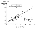
- the distortion rate d had a high correlation with the pressure differences (y 5 - y 4 ) in the values of blood pressure, which difference was the amplitude of a dicrotic wave from the dicrotic notch, with the coefficient of correlation (R 2 ) being 0.77.
- This correlation is shown in Figure 10.
- the inventors of the present invention made the following analysis on the hypothesis that specialists in Oriental medicine sensed the features of the dicrotic wave and tidal wave to diagnose the pulse condition.
- f1, f2, f3, ⁇ , f10 indicate the amplitudes and phases of a fundamental wave, second harmonic, third harmonic, ..., tenth harmonic respectively.
- the waveform wf1 is the sum of the fundamental wave f1 and the second harmonic f2
- waveform wf2 is the sum of the fundamental wave f1 to the third harmonic, ...
- the waveform wf9 is the sum of the fundamental wave f1 to the tenth harmonic f10.
- Figure 14 shows the amplitudes of the dicrotic wave and the tidal wave in the pulse waveform representing the pulse condition which is described in Figures 11 to 13.
- the amplitudes of the dicrotic waves are relatively as high as 7.3 mmHg and 10.6 mmHg in a Hua mai and in a Ping mai respectively whereas the amplitude of the dicrotic wave in a Xuan mai is as small as 2.9 mmHg.
- the amplitudes of the tidal waves in a Hua mai and in a Ping mai are 0 whereas the amplitude of the tidal wave in a Xuan mai is 3.8 mmHg.
- each dicrotic wave has specific characteristics which are observed in the fundamental wave f1 to the fourth harmonic f4.
- the tidal wave has specific characteristics which are observed in high frequency components, e.g., the fifth harmonic f5 to the seventh harmonic f7.
- Figure 15 shows the percentage ratio of the amplitude of each harmonic to the amplitude of the fundamental wave for every pulse condition.
- the ratio of the sum of the second harmonic f2, the third harmonic f3, and the fourth harmonic f4 to the fundamental wave f1 in terms of amplitude, namely, (f2 + f3 + f4)/fl this is 1.74 in a Hua mai and 1.5 in a Ping mai. It is therefore possible to discriminate between a Hua mai and a Ping mai on the basis of these values.
- the pulse wave examination apparatus is structured based on the theoretical basis as described above.
- the pulse wave forms detected from subjects are treated by frequency analysis to extract a tidal wave component and a dicrotic wave component thereby judging the pulse condition on the basis of the results of the extraction.
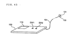
- the external structure of the pulse wave examination apparatus will be described later in the section "10. External structures of aforementioned embodiments" .
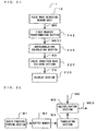
- FIG. 1 is a block diagram showing the functional structure of the pulse wave examination apparatus according to this embodiment.
- a pulse wave detecting section 10 detects the pulse waveform of, for instance, the periphery (e.g., arteria radialis) of a subject, to output the detected signal as MH to a body movement eliminating section 30.
- the periphery e.g., arteria radialis
- a body movement detecting section 20 comprises, for instance, an acceleration sensor and detects the body movement of a subject to output the detected signal as a signal TH to a waveform treating section 21.
- the waveform treating section 21 comprises, for instance, a low-pass filter, and performs waveform-shaping treatment of the signal TH output from the body movement detecting section 20 to output a signal MHt showing a body movement component.
- the body movement eliminating section 30 subtracts the signal MHt showing a body movement component from the signal MH output from the pulse wave detecting section 10 to output a signal MHj showing a pulse wave component.
- the pulse wave examination apparatus is a type treating the pulse waveform detected from a subject.
- the signal MHt showing a body movement component is superimposed on the signal MH detected by the pulse wave detecting section 10.
- MH MHt + MHj and hence the signal MH output from the pulse wave detecting section 10 does not show the exact pulse waveform of the subject.
- the body movement component MHt included in the signal MH is not considered to be just the signal TH showing the body movement of the subject but is considered to be somewhat dulled.
- the body movement eliminating section 30 uses, as the signal MHt, a signal produced by shaping the waveform of the signal TH in the waveform treating section 21.
- the signal TH shows the body movement of the subject directly and is output from the body movement detecting section 20.
- the body movement eliminating section 30 subtracts the signal MHt from the signal MH output from the pulse wave detecting section 10 to eliminate the influence of the body movement, thereby outputting the signal MHj showing the pulse component.
- the type, number of stages, constant, and the like of the low-pass filter used in the waveform treating section 21 are determined based on the data measured in practice.
- a judging section 22 determines whether body movement is present or not, based on the body movement waveform TH, to yield a control signal C. Specifically, the judging section 22 makes a judgment by comparing a threshold value with the body movement waveform TH.
- the threshold value is prescribed in advance, taking a noise level into consideration, so that whether the body movement is present or not can be determined.
- the operations of the waveform treating section 21 and body movement component eliminating section 30 are suspended.
- the pulse waveform MH is output directly from the body movement component eliminating section 30. This can improve the SN ratio of the output signal from the body movement component eliminating section 30 and reduce power consumption in the apparatus.
- an FFT treating section 40 provides the signal MHj, showing a pulse wave component, with FFT treatment to carry out frequency analysis of the pulse wave component.
- the result of the frequency analysis can be obtained in the form of a plurality of line spectrums. Then the frequency and the energy level of every line spectrum are calculated.
- the FFT treating section 40 compares this spectrum data and specifies one having the highest energy level as the fundamental wave f1 of the pulse wave component.
- the FFT treating section 40 also multiplies the frequency of the fundamental wave f1 integral-fold to specify each harmonic, and outputs pulse wave analysis data MKD showing each energy level of the fundamental wave f1 and of the second harmonic f2 to the tenth harmonic f10.
- a tidal wave-character extracting section 50 yield a tidal wave-character data TWD showing the characteristics of the tidal wave on the basis of the pulse wave analysis data MKD.
- the characteristics of the tidal wave can be expressed by the ratio of the sum of the fifth harmonic f5, the sixth harmonic f6, and the seventh harmonic f7 to the fundamental wave f1 in the pulse waveform.
- a dicrotic wave-character extracting section 60 yields dicrotic wave-character data DWD showing the characteristics of the dicrotic wave.
- the characteristics of the dicrotic wave can be expressed by the ratio of the sum of the second harmonic f2, the third harmonic f3, and the fourth harmonic f4 to the fundamental wave f1 in the pulse waveform.
- a pulse condition judging section 70 judges the pulse condition on the basis of the tidal wave-character data TWD and the dicrotic wave-character data DWD to yield pulse condition data ZD showing the type of pulse condition of the subject.
- the pulse condition judging section 70 compares the tidal wave-character data TWD with a first threshold value to yield pulse condition data ZD1 showing that the pulse condition is a Xuan mai if the tidal wave-character data TWD exceeds the first threshold value.
- the first threshold value is prescribed in advance so as to determine whether the tidal wave-character data TWD shows a Xuan mai or not. In this instance, the first threshold value is designed to be 0.41.
- the dicrotic wave-character data DWD is compared with a second threshold value. If the dicrotic wave-character data DWD is less than the second threshold value, pulse condition data ZD2 showing that the pulse condition is a Ping mai is yielded, whereas, if the dicrotic wave-character data DWD exceeds the second threshold value, pulse condition data ZD3 showing that the pulse condition is a Hua mai is yielded.
- the second threshold value is prescribed in advance so as to determine whether the dicrotic wave-character data DWD shows a Ping mai or a Xuan mai. In this instance, the second threshold value is designed to be 1.62.
- a notifying section 80 is a type which outputs pulse condition data ZD by display or voice. For instance, the notifying section 80 displays the characters "Hua mai, Ping mai, Xuan mai" or symbols, e.g., icons. This allows the subject and a third party, e.g. , a doctor to recognize the pulse condition.
- the signal MHj is subjected to FFT treatment to yield the fundamental wave f1 of the pulse wave component and each of harmonics f2 to f10 as the pulse wave analysis data MKD, which is then supplied to the tidal wave-character extracting section 50 and the dicrotic-character extracting section 60 (Step S3).
- the tidal wave-character extracting section 50 calculates the ratio of the sum of the fifth harmonic f5, the sixth harmonic f6, and the seventh harmonic f7 to the fundamental wave f1 of the pulse waveform, which ratio expresses the characteristics of the tidal wave, to yield the tidal wave-character data TWD.
- the dicrotic wave-character extracting section 60 calculates the ratio of the sum of the second harmonic f2, the third harmonic f3, and the fourth harmonic f4 to the fundamental wave f1 of the pulse waveform, which ratio expresses the characteristics of the dicrotic wave, to yield the dicrotic wave-character data DWD (Step S4).
- the pulse condition judging section 70 first compares the tidal wave-character data TWD with a first threshold value (Step S5) . If the tidal wave-character data TWD exceeds the first threshold value (0.41), pulse condition data ZD1 showing that the pulse condition is a Xuan mai is yielded in Step S6.
- the pulse condition judging section 70 determines whether the dicrotic wave-character data DWD is less than a second threshold value (1.62) or not, and yields pulse condition data ZD2 showing that the pulse condition is a Ping mai if the dicrotic wave-character data DWD is less than the second threshold value in Step S8.
- Step S7 if the dicrotic wave-character data DWD exceeds the second threshold value (1.62), the result of the judgment in Step S7 is "NO" and pulse condition data ZD3 showing that the pulse condition is a Hua mai is yielded in Step S9.
- the Hua mai and the Ping mai are characterized by the dicrotic wave
- the Xuan mai is characterized by the tidal wave
- the pulse waveform is subjected to FFT treatment.
- frequency components corresponding to the dicrotic wave and to the tidal wave are respectively extracted to make a judgment on the basis of the extraction.
- the dicrotic wave and the tidal wave appear in a partial period in the pulse waveform. Accordingly, if the frequency analysis is carried out only in the periods corresponding to the dicrotic wave and tidal wave, the judgment accuracy for the pulse condition can be further improved.
- the pulse waveform is treated using wavelet transformation performing frequency analysis and time analysis simultaneously to specify the pulse condition.
- the pulse wave examination apparatus shown in Figure 3 is the same as the pulse wave examination apparatus shown in Figure 1 except that a wavelet transformation section 41 is used in place of the FFT treating section 40, a tidal wave/dicrotic wave detecting section 42 which specifies the time positions of the tidal wave and dicrotic wave is installed, and the inner structures of a tidal wave-character extracting section 50, dicrotic wave-character extracting section 60 and pulse condition judging section 70 differ from those used in the first embodiment.
- the second embodiment will be hereinafter described mainly with respect to the different points between the two embodiments.
- a wavelet is a unit which cuts out a part of the signal.
- the wavelet transformation signifies the magnitude of each part of the signal cut out by this unit.
- a function ⁇ (x) localized in terms of time and frequency is introduced as a mother wavelet.
- the wavelet ⁇ ((x-b)/a) is formed when the mother wavelet ⁇ (x) is translated by "b” and expanded "a” times.
- the width of the mother wavelet ⁇ (x) is extended in relation to the scale parameter "a". 1/a therefore corresponds to the frequency.
- the wavelet transformation section 41 is structured so as to calculate the equation (2). The detail of the structure is as shown in Figure 4.
- a signal MHj output from a body movement component eliminating section 30 is supplied to a waveform shaping section 400 and an A/D converter 410.
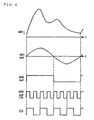
- the waveform shaping section 400 yields a control signal CS and a clock CK which are synchronized with the pulse waveform MHj.
- a block diagram of the waveform shaping section 400 is shown in Figure 5.
- a ringing filter 401 is a filter with a high Q value with the center frequency being 2.2 Hz and the passing band being 0.8 Hz to 3.5 Hz. Since the fundamental wave component of the pulse waveform is generally in a range between 0.8 Hz and 3.5 Hz, the fundamental wave component is extracted when the pulse waveform MHj passes through the ringing filter 401. For instance, as shown in Figure 6, when the pulse waveform MHj is input to the ringing filter 401, its output is that shown as 401 out in Figure 6.
- a zero-cross detecting circuit 402 comprises a comparator and the like and compares an output signal from the ringing filter 401 with the ground level to yield a rectangular wave.
- the rectangular wave is synchronized with the pulsation. For instance, if the signal from the ringing filter 401 is that shown as "401 out” in Figure 6, an output signal from a zero-cross detecting circuit 402 is that shown as "402 out” in the same figure.
- a comparing section 403, a loop filter 404, a voltage control oscillation circuit 405, and a frequency divider 406 comprise a phase lock loop.
- the comparing section 403 outputs an error signal corresponding to a phase difference between the two output signals.
- the voltage control oscillation circuit 405 outputs a clock signal CK.
- the clock signal CK is divided in 1/N by the frequency divider 406 and is fed back to the other input port of the comparing section 403.
- the frequency of the clock signal CK becomes 8 times the frequency of the output signal from the zero-cross detecting circuit 402 as shown by "405 out CK" in Figure 6.
- the clock signal CK is then divided in half in a frequency divider 407 and output as a control signal CS as shown in Figure 6.
- the pulse waveform MHj is also converted into a digital signal by an A/D converter 410 shown in Figure 4 and the digital signal is then stored in a first memory 420 and a second memory 430.
- the control signal CS is supplied directly to a write-enable terminal of the first memory 420.
- the control signal CS is reversed by an inverter 440 and the reversed signal is supplied to a write-enable terminal of the second memory 430 Hence, the fist and second memories 420, 430 store the pulse waveform MH alternately at intervals of the period.
- the symbol 450 represents a multiplexer which selects the pulse wave data MD read out alternately from the first and second memories 420, 430 to output the selected data to a basic function developing section W. In this manner, the pulse wave data MD is read out from the second memory 430 during the writing time of the first memory 420 and the pulse wave data MD is written in the second memory 430 during the reading time of the first memory 420.
- the basic function developing section W has a structure enabling the calculation of the foregoing equation (2).
- the aforementioned clock signal CK is supplied to the basic function developing section W and a calculation process is carried out at intervals of the period.
- the basic function developing section W comprises a basic function storing section W1 for storing the mother wavelet ⁇ (x), a scale conversion section W2 for converting the scale parameter a, a buffer memory W3, a translating section W4 for carrying out parallel translation, and a multiplication section W5.
- a Gabor wavelet, Mexican hut, Haar wavelet, Meyer wavelet, Shannon wavelet or the like may be applied and, in this embodiment, a mother wavelet called symlets 5 is used to advantageously extract the characteristics of the pulse waveform.
- the scale conversion section W2 carries out the conversion of the scale parameter "a".
- the scale parameter "a" corresponds to the period.
- the mother wavelet ⁇ (x) is expanded on the time axis.
- the scale conversion section W2 performs compensation treatment to compensate the reduction in data and carries out curtailed treatment when "a" is small to yield a function ⁇ (x/a). This data is stored in the buffer memory W3 once.
- the translating section W4 reads out the function ⁇ (x/a) from the buffer memory W3 with timing corresponding to the translate parameter b to translate the function ⁇ (x/a) thereby yielding a function ⁇ ((x - b)/a)
- a multiplication section W5 multiplies a variable 1/a 1 ⁇ 2 , by the function ⁇ ((x-b)/a) and by the pulse wave data MD to undergo wavelet transformation at each beat to yield the pulse wave analysis data MKD.
- the pulse wave analysis data MKD is divided into frequency zones, for example, 0 Hz-0.5 Hz, 0.5 Hz-1.0 Hz, 1.0 Hz-1.5 Hz, 1.5 Hz-2.0 Hz, 2.0 Hz-2.5 Hz, 2.5 Hz-3.0 Hz, 3.0 Hz-3.5 Hz, and 3.5 Hz-4.0 Hz and output.
- a tidal wave/dicrotic wave detecting section 42 compares the pulse wave analysis data MKD in a certain frequency zone with a threshold value to yield control signals ct and cd which specify the time positions of the tidal wave and dicrotic wave respectively.
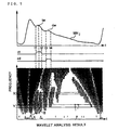
- the tidal wave and the dicrotic wave are shown by tw and dw respectively.
- the result of wavelet analysis as shown in the same figure is obtained.
- the values of the pulse wave analysis data MKD is expressed by shading. The darker the color of the parts, the larger the values of the pulse wave analysis data MKD, whereas the lighter the color of the parts, the smaller the values of the pulse wave analysis data MKD.
- the zones A and B surrounded by the parts (white) with a small value for the pulse wave analysis data MKD are located in a time-domain corresponding to the tidal wave.
- the part having a small value in terms of the pulse wave analysis data in the direction of the Y or frequency axis shows that the energy of the pulse waveform MHj in its period is at a low level.
- the pulse waveform MHj is flat.
- the boundary between the zones A and B corresponds to a peak of the tidal wave tw.
- the time position of the tidal wave tw can be detected based on its change.
- a comparison of the value of the pulse wave analysis data MKD in a frequency zone X with a threshold value yields a control signal ct specifying the time positions between t1 and t2 of the tidal wave tw as shown in Figure 7.
- a comparison of the value of the pulse wave analysis data MKD in a frequency zone Y with a threshold value yields a control signal dw specifying the time positions between t3 and t4 of the tidal wave tw as shown in Figure 7.
- the tidal wave-character extracting section 50 specifies the time position of the tidal wave on the basis of the control signal ct and adds data in a specific frequency zone among the pulse wave analysis data MKD in the specified period.
- the wavelet transformation section 41 is, for instance, designed to be formed of a filter bank in which the characteristics of a high frequency filter 1A and low frequency filter 1B are varied by the clock signal CK synchronized with the pulse waveform MHj as will be mentioned later in the section "14 Other embodiments" (6) with reference to Figure 58.
- the pulse wave analysis data corresponding to the fundamental wave f1 of the pulse waveform MHj is M*1
- the parts showing the characteristics of the tidal wave appear on the fifth harmonic f5 to the seventh harmonic f7 and hence the wavelet transformation section 41 adds M*5, M*6 and M*7 to calculate the tidal wave-character extracting data TWD.
- the dicrotic wave-character extracting section 60 specifies the time position of the dicrotic wave on the basis of the control signal cd and adds data in a specific frequency zone among the pulse wave analysis data MKD in this period.
- the wavelet transformation section 41 is formed in such a structure, for instance, as in the description of the tidal wave-character extracting section 50, and the pulse wave analysis data corresponding to the fundamental wave f1 of the pulse waveform MHj is M*1, the parts showing the characteristics of the dicrotic wave appear on the second harmonic f2 to the fourth harmonic f4 and hence the wavelet transformation section 41 adds M*2, M*3 and M*4 to calculate the dicrotic wave-character extracting data DWD.
- the tidal wave-character extracting section 50 and the dicrotic wave-character extracting section 60 extract the characteristics of the tidal wave and dicrotic wave from the aspect of the time-domain as well as the frequency zone by making clever use of the character of the wavelet transformation which can divide the waveform into a frequency zone and a time-domain to carry out waveform analysis. The characteristics can be thereby extracted with high accuracy.
- a pulse condition judging section 70 compares the tidal wave-character extracting data TWD and the dicrotic wave-character extracting data DWD with each threshold value to judge the pulse condition, such as a Ping mai, Hua mai, or Xuan mai, to yield a pulse condition data ZD.
- a notifying section 80 notifies the subject or a third party, e.g., a doctor, of the pulse condition data ZD by a display, voice or the like in the same way as in the first embodiment.
- the frequency component can be analyzed in a limited period in which the tidal wave and the dicrotic wave appear by undergoing wavelet transformation of the pulse waveform detected from the subject.
- the characteristics of the tidal wave and dicrotic wave can be extracted with accuracy to thereby make an exact judgment of the pulse condition.
- the pulse waveform expresses pulsation when the flow of blood pumped out to an aorta by the contraction of the heart is propagated through an artery and hence has a certain period synchronized with the beat of the heart.
- Analyzing technics for analyzing a periodic waveform to extract its characteristics include a spectrum analysis represented by FFT (Fast Fourier Transformation). The inventors of the present invention, however, remarked an autocorrelation function which can be dealt with by a simple calculation.
- a waveform represented by the above equation overlaps the original waveform when it is shifted by an integral multiple of the period. If the irregular variation x(t) is strongly periodical, the wave form becomes similar to the original waveform when it is shifted on the time axis by integral multiple of the period.
- the similarity of a waveform, shifted by a certain time ⁇ , to the original waveform is investigated and the correlation between x (t) and x (t+ ⁇ ) is des irably calculated to discriminate a periodic component in the variations.
- Figures 16 to 18 show the autocorrelation function coefficients of a Xuan mai shown in Figure 45C, a Ping mai shown in Figure 45A, and a Hua mai shown in Figure 45B respectively. Comparing these figures, a waviness becomes visible in the waveform of the autocorrelation coefficient R( ⁇ ) as the pulse condition changes from a Xuan mai to a Hua mai via a Ping mai. This corresponds to the fact that a Xuan mai has a smooth waveform, a Ping mai includes three peaks but these peaks are small in size and a Hua mai include two large peaks. Stated in another way, the characteristics of each waveform are reflected in the autocorrelation coefficient R( ⁇ ). Moreover, the waveform of the autocorrelation coefficient R( ⁇ ) is obtained based on a pulse waveform formed over a relatively long period and hence the characteristics of the pulse waveform can be extracted with accuracy.
- the instantaneous magnitude of the autocorrelation coefficient R( ⁇ ) is, unlike the instantaneous magnitude of the pulse waveform, given as the time average. Therefore even if the SN ratio of the pulse waveform detected from a living body is somewhat impaired, noises are averaged with the result that the SN ratio is improved. Furthermore, the autocorrelation coefficient R( ⁇ ) is formed by normalizing the autocorrelation function C ( ⁇ ) and is hence convenient for analysis by comparing pulse waveforms having different amplitudes.
- the inventors of the present invention determined a criteria specifying the pulse condition by making clever use of the character of the autocorrelation coefficient R( ⁇ ) and have found a pulse wave examination apparatus which judges the pulse condition of the living body according to the criteria.
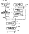
- Figure 19 is a block diagram showing the electrical structure of the pulse wave examination apparatus.
- the pulse wave examination apparatus 1 comprises the pulse wave detecting section 10 for detecting the pulse waveform MH, an autocorrelation calculating section 210 for calculating autocorrelation data RD on the basis of the pulse waveform MH, a pulse condition data yielding section 220 for yielding the pulse condition data ZD on the basis of the autocorrelation RD and a display section 230.
- the autocorrelation calculating section 210 comprises a waveform treating section 211, a memory 212, a multiplication section 213, an average value calculating section 214 and a normalization calculating section 215.
- the memory 212 stores the pulse waveform MH in a period of at least one beat.
- x(t) in this embodiment is the pulse waveform MH synchronized with the beat period
- the calculation may be made based on the pulse waveform MH in a period of at least one beat.
- the waveform shaping of the pulse waveform MH is carried out by the waveform treating section 211, the shaped waveform is converted into a rectangular wave synchronized with the pulse wave period, and a write control signal WE for controlling the write action of the memory 212 is yielded based on the rectangular wave. For instance, the pulse waveform MH in four periods is written in the memory 212 by the write control signal WE.
- the multiplication section 213 read out a pulse waveform MH1 corresponding to x(t) and a pulse waveform MH2 corresponding to x(t + T), multiplies the two and outputs the result of the multiplication.
- the average value calculating section 214 calculates the ensemble average of MH1 ⁇ MH2 corresponding to the ensemble average of x(t)x(t + ⁇ ) and outputs the result of the calculation.
- the normalization calculating section 215 normalizes the result, calculated by the average value calculating section 214, by the autocorrelation function C(0) to yield the autocorrelation data RD. More specifically, the normalization is made by the ensemble average of X 2 (t), namely, MH1 2 . As a result, the autocorrelation data RD shows the autocorrelation coefficient R(T) of the pulse waveform MH.
- the autocorrelation coefficient RD is examined for the pulse waveform MH of each pulse condition shown in Figures 45A to 45C.
- the minimum value of the autocorrelation coefficient R ( ⁇ ) is 0.2 in a Xuan mai.
- the minimum values of the autocorrelation coefficient R(T) are 0.32 and 0.3 in a Ping mai and in a Hua mai respectively.
- the pulse condition is therefore judged to be a Xuan mai when the minimum value of the autocorrelation coefficient is less than 0.25.
- the pulse condition may be judged to be a Ping mai when this ratio exceeds 47% and to be a Hua mai when the ratio is less than 47%.
- the pulse condition data yielding section 220 judges the pulse condition on the basis of the above judging criteria.
- the pulse condition data yielding section 220 comprises a minimum value detecting section 221 and a first comparing section 222 for detecting a pulse condition of a Xuan mai, a time measuring section 223, a calculating section 224 and a second comparing section 225 for detecting a pulse condition of a Ping mai or Hua mai and a data yielding section 226 for yielding the pulse condition data ZD.
- the minimum value detecting section 221 detects the minimum value of the autocorrelation data RD in a period corresponding to a period of one beat.
- the first comparing section 222 determines whether the detected minimum value is less than 0.25 or not and outputs the result of the judgment to the data yielding section 226.
- the time measuring section 223 compares the autocorrelation data RD with a prescribed threshold value (0.5) and measures a time interval in which the autocorrelation data RD exceeds the threshold value (0.5).
- the calculating section 224 calculates the ratio of the measured time interval to a period of one beat. Incidentally, the period of one beat is designed to be supplied from the aforementioned waveform treating section 211.
- the second comparing section 225 determines whether the calculated result exceeds a prescribed threshold value (47%).
- the data yielding section 226 yields the pulse condition data ZD on the basis of each result determined in the first and second comparing sections 222 and 225.
- the pulse condition data ZD1 showing a Xuan mai is yielded.
- the pulse condition data ZD2 showing a Ping mai results whereas when its period is judged to be less than 47%, the pulse condition data ZD3 showing a Hua mai is obtained.
- the display section 230 comprises a ROM, a control circuit, a liquid crystal display device and the like.
- the control circuit detects this, reads out characters stored in the ROM and displays these characters on the liquid crystal display.
- characters specific symbols or icon as well as the characters "Ping mai”, “Xuan mai” and “Hua mai” may be used.
- the display section 230 makes it possible to notify the user or a doctor of the physical condition.
- the autocorrelation calculating section 210 and the pulse condition data yielding section 220 are constituted of CPUs, memories and the like.
- the CPU undergoes various calculating processes and comparing processes on the basis of control programs stored in part of the memories to yield the pulse condition data ZD.
- Figure 20 is a flow chart showing the action of the pulse wave examination apparatus.
- the pulse wave detecting section 10 detects the pulse waveform MH (Step S1).
- the pulse waveform MH is supplied to the autocorrelation calculating section 210, the pulse waveform MH is written in the memory 212 and read out in a fixed period later.
- An autocorrelation function is calculated based on the read pulse waveform MH and the calculated result is normalized to yield the autocorrelation data RD showing the autocorrelation coefficient R( ⁇ ) (Step S2) .
- the pulse condition yielding section 220 yields the pulse condition data ZD on the basis of the autocorrelation data RD in the manner described below.
- the first comparing section 222 determines whether the minimum value is less than 0.25 or not (Step S4) .
- the result of the determination is expressed as YES and the stage is forwarded to the next step (Step S5) in which the pulse condition is judged to be a Xuan mai to yield the pulse condition data ZD1 in the data yielding section 226.
- the time measuring section 223 measures a time interval in which the autocorrelation data RD exceeds 0.5, in a period corresponding to a period of one heartbeat (Step S6) and the calculating section 224 calculates the ratio of the measured time to the period of one beat.
- the second comparing section 225 determines whether the result calculated in the calculating section 224 exceeds 47% or not (Step S8). When this result exceeds 47%, the stage is forwarded to the next step (Step S9) in which the pulse condition is judged to be a Ping mai which allows the data yielding section 226 to yield the pulse condition data ZD2. On the other hand, when the result calculated in the calculating section 224 does not exceed 47%, the stage is forwarded to the next step (Step S10) in which the pulse condition is judged to be a Hua mai to yield the pulse condition data ZD3 in the data yielding section 226.
- the pulse wave examination apparatus 1 judges the pulse condition on the basis of the autocorrelation data RD of the pulse waveform MH and hence the subject and a doctor can know the living condition from the detected result of the pulse wave.
- the electrical structure of the pulse wave examination apparatus of the fourth embodiment is the same as that of the third embodiment except for the structure of a pulse condition data yielding section 220.
- Figure 21 is a block diagram of the pulse condition data yielding section 220 according to the fourth embodiment.
- the pulse condition data yielding section 220 in this embodiment comprises a minimum value detecting section 221 and a first comparing section 222 for determining whether the pulse condition is a Xuan mai or not, a change rate calculating section 227, a maximum value detecting section 228 and a second comparing section 225 for determining whether the pulse condition is a Ping mai or a Hua mai, and a data yielding section 226 for yielding a pulse condition data ZD on the basis of these determined results.
- the first comparing section 222 determines whether the pulse condition is a Xuan mai or not based on whether the minimum value of the autocorrelation data RD detected by the minimum value detecting section 221 exceeds 0.25 or not as in the third embodiment.
- the change rate calculating section 227 calculates the change rate RDd of the autocorrelation data RD. If the autocorrelation data RD is as shown in Figures 16 to 18, each change rate RDd of a Xuan mai, Ping mai and Hua mai is as shown in Figure 22. It is seen from this figure that the maximum value of the change rate RDd is about 0.1 in a Hua mai whereas it is 0.072 in a Ping mai. This corresponds to the fact that the waviness of the pulse waveform MH of a Ping mai is greater than that of the pulse waveform of a Hua mai. It is therefore possible to determine whether the pulse condition is a Ping mai or a Hua mai by the maximum value of the change rate RDd. When the maximum value of the change rate RDd exceeds 0.085, the pulse condition may be judged to be a Hua mai whereas, when it does not exceeds 0.085, the pulse condition may be judged to be a Ping mai accordingly.
- the maximum value detecting section 228 detects the maximum of the change rate RDd within a prescribed period of time longer than a period of one beat.
- the second comparing section 225 compares the maximum value of the change rate with a prescribed threshold value (0.85) to determine whether the maximum value of the change rate RDd exceeds the threshold value or not.
- the data yielding section 226 yields a pulse condition data ZD on the basis of each result determined by the first and second comparing sections 222 and 225. First, when the minimum value is judged to be less than 0.25 in the first comparing section 222, a pulse condition ZD1 showing a Hua mai is obtained. Then, when the maximum value of the change rate RDd is judged to be less than 0.85 in the second comparing section 225, pulse condition data ZD2 showing a Ping mai is obtained whereas, when it is judged to exceed 0.85, a pulse condition data ZD3 showing a Hua mai results.
- FIG 23 is a flow chart showing the action of the pulse wave examination apparatus .
- the actions from Step S1 to Step S5 are the same as those of the pulse wave examination apparatus of the third embodiment described with reference to Figure 20 and hence description of these steps is omitted.
- Step S11 when the change rate calculating section 227 detects the change rate RDd of the autocorrelation data RD, the maximum value detecting section 228 detects the maximum value of the change rate RDd in a period corresponding to a period of one beat (Step S12). For instance, if the calculated change rate RDd is that of a Hua mai shown in Figure 22, a value of about 0.1 is detected as the maximum value.
- the second comparing section 225 determines whether or not the maximum value exceeds 0.85.
- the stage is forwarded to Step S14 in which the pulse condition is judged to be a Ping mai and the data yielding section 226 yields pulse condition data ZD2.
- the stage is forwarded to Step S15 in which the pulse condition is judged to be a Hua mai and the data yielding section 226 produces pulse condition data ZD3.
- the maximum value of the change rate RDd is compared with the threshold value to determine whether the pulse condition is a Ping mai or a Hua mai.
- the autocorrelation data RD is obtained based on the pulse waveform MH output from the pulse wave detecting section 10 to judge the pulse condition.
- the body movement causes the blood flow of the subject to fluctuate. Because of this, a component due to the body movement is superimposed on the pulse waveform MH output from the pulse wave detecting section 10.
- the magnitude of the body movement component depends on the degree of movement. When the quantity of the movement is large, the body movement component superimposed on the pulse waveform MH increases, causing difficulty in making an exact judgment of the pulse condition.
- the body movement component is eliminated from the pulse waveform MH and the pulse condition is judged based on the resulting pulse waveform.
- FIG. 24 is a block diagram showing the electrical structure of the pulse wave examination apparatus according to the fifth embodiment of the present invention.
- Each structure of the autocorrelation calculating section 210, pulse condition data yielding section 220 and display section 230 in this embodiment is the same as described in the third and fourth embodiments, therefore further description of these sections is omitted.
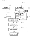
- a body movement eliminating section 30 and sections prior to this section namely, a pulse wave detecting section 10, a body movement detecting section 20, a judging section 22, and a waveform treating section 21 are the same as those described in the first embodiment. Therefore, further description of these sections is omitted.
- the pulse wave examination apparatus of this embodiment provides a body movement-eliminated pulse waveform MHj owing to the above structure.
- the autocorrelation calculating section 210 can yield the autocorrelation data RD on the basis of the body movement-eliminated pulse waveform MHj.
- the pulse condition can be specified in a condition free of the influence of body movement.
- Figure 25 is a block diagram of a pulse wave examination apparatus 1 according to the sixth embodiment.
- a body movement component TH is detected using a body movement detecting section 20 and a waveform treating section 21, as in the fifth embodiment
- the sixth embodiment differs from the fifth embodiment in that the elimination of body movement mentioned in the fifth embodiment is made using wavelet transformation.
- a first wavelet transformation section 243 undergoes a well-known wavelet transformation of a pulse waveform MH output from the pulse wave detecting section 10 to yield a pulse wave analysis data MKD.
- the second wavelet transformation section 245 undergoes a well-known wavelet transformation of a body movement waveform TH output from the body movement detecting section 20 to yield a body movement analysis data TKD.
- These first and second wavelet transformation sections 243 and 245 have the same structures as those described in the second embodiment.
- Figure 26 shows the pulse wave analysis data MKD in part of the period of the pulse waveform MH.
- a period T is close to a peak P4 and the pulse wave analysis data MKD is obtained at time intervals set by dividing the period T into 8 parts.
- the frequency resolution and the time resolution is in tradeoff relation. Hence, if the frequency resolution is sacrificed, the pulse wave analysis data can be obtained at more reduced intervals.
- the first frequency correcting section 244 makes frequency corrections of the pulse analysis data MKD.
- the term "1/a 1/2 " corresponding to the frequency is present. The effect of this term must be corrected when data is compared between different frequency zones.
- a first frequency correcting section 244 is therefore provided and multiplies a wavelet data WD by a factor a 1/2 to yield pulse wave-corrected data MKDa. This enables a correction on the basis of each corresponding frequency so as to obtain a constant power density per frequency.
- the second frequency correcting section 246 makes the frequency correction of the body movement analysis data TKD in the same manner as in the case of the first frequency correcting section 244 to produce a body movement-corrected data TKDa from the body movement analysis data TKD.
- a body movement component eliminating section 240 subtracts the body movement-corrected data TKDa from the pulse wave-corrected data MKDa to yield a body movement-eliminated pulse wave data MKDaj.
- the body movement is analyzed on the assumption that the subject lifts a cup with his hand and then puts it back in the original location.
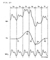
- the pulse waveform MH shown in Figure 27 is detected by the pulse wave detecting section 10 and, at the same time, the body waveform TH is detected by the body movement detecting section 20.
- the body waveform TH starts to increase from time T1, reaches a positive peak at time T2, decreases gradually, passes a level 0 at time T3, reaches a negative peak at time T4 and returns to a level 0 at time T5.
- the body movement waveform TH is detected by the body movement detecting section 20 using an acceleration sensor.
- the time T3 corresponds to the time at which the subject has lifted the cup to the maximum height
- the time T1 corresponds to the time at which the lifting starts
- the time T4 corresponds to the time at which the lifting has finished. Accordingly the period between the time T1 and the time T4 is the period in which body movement is present.
- the pulse waveform MHj shown in Figure 27 is a pulse waveform formed on the assumption that no body movement is present.
- the frequency of the fundamental wave of the pulse waveform MH is 1.3 Hz.
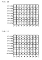
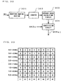
- Figure 28 shows the pulse wave-corrected data MKDa in a period Tc (see Figure 27) and Figure 29 shows the body movement-corrected data TKDa in the period Tc. It is seen from this figure that frequency components with a relatively large level are present in a frequency zone between 0.0 Hz and 1.0 Hz in the body movement waveform TH.
- the body movement eliminating section 240 subtracts the body movement-corrected data TKDa from the pulse wave-corrected data MKDa to yield a body movement-eliminated pulse wave data MKDaj excluding the body movement component as shown in Figure 30. This makes it possible to eliminate the effect of body movement even if body movement is present.
- the judging section 22 compares the body movement waveform TH with a prescribed threshold value to yield a control signal C showing the presence or absence of body movement, and supplies this signal to the waveform treating section 21, the second wavelet converting section 245, and the second frequency correcting section 246. This ensures that each operation of the waveform treating section 21, the second wavelet converting section 245, and the second frequency correcting section 246 is suspended when there is no body movement, thereby reducing calculation time and power consumption and improving the SN ratio.
- an inverse wavelet transformation section 247 undergoes the inverse wavelet transformation of the body movement-eliminated pulse wave data MKDaj to yield a body movement-eliminated pulse waveform MHj.
- the inverse wavelet transformation section 247 undergoes the inverse wavelet transformation based on the equation (4) to reconstruct the waveform.
- the autocorrelation calculating section 210 produces autocorrelation data RD on the basis of the body movement-eliminated pulse waveform MHj.
- the pulse condition data yielding section 220 yields pulse condition data ZD on the basis of the autocorrelation RD and the display section 230 then displays such characters as "Ping mai”, “Xuan mai” and “Hua mai” indicated by the pulse condition data ZD, or characters corresponding to each pulse condition.
- the display section 230 ensures that the subject or a doctor can find the pulse condition.
- the sixth embodiment is designed so that the autocorrelation data RD is yielded based on the body movement-eliminated pulse waveform MHj excluding a body movement component, hence the subject can detect his pulse condition continuously in his daily life.
- the body movement waveform TH is detected by the body movement detecting section 20
- the pulse waveform MH is compared with the body movement waveform TH
- a body movement component included in the frequency component of the pulse waveform MH is eliminated to calculate the autocorrelation data RD thereby specifying the pulse condition.
- the above structure requires the body movement section 20 and the waveform treating section 21, causing the structure to be complicated.
- a seventh embodiment of the present invention is developed in view of this situation and provides a pulse wave examination apparatus which has a simple structure and can detect a pulse condition exactly even if body movement exists.
- Figure 31 is a block diagram of the pulse wave examination apparatus according to the seventh embodiment, which is the same as the pulse wave examination apparatus according to the sixth embodiment shown in Figure 25 except that the body movement detecting section 20, the waveform treating section 21, the second wavelet transformation section 245 and the second frequency correcting section 246 are omitted and except for the inner structure of the body movement component eliminating section 240.
- the following is a description of the difference between the two embodiments.
- a body movement component eliminating section 240 separates and removes a body movement component from the pulse wave-corrected data MKDa to yield body movement-eliminated pulse wave data MKDaj.
- the body movement component eliminating section 240 makes use of the property of body movement as will be mentioned below.
- the body movement is caused by the up-and-down motion of an arm or the swing of an arm.
- the frequency component of the body movement waveform TH is not very high and is usually in a range between 0 Hz and 1 Hz in daily life. In this case, most of the frequency of the fundamental wave of the pulse waveform is in a range between 1 Hz and 2 Hz. In daily life, therefore, the frequency component of the body movement waveform TH is in a frequency zone lower than the fundamental frequency of the pulse waveform MH.
- the frequency component of the body movement waveform TH is slightly increased by the effect of the swing of an arm and the like.
- the number of beats increases in relation to the quantity of movement and the frequency of the fundamental wave of the pulse waveform MH is thereby increased at the same time. Therefore, even during a sport, the frequency component of the body movement waveform TH is in a frequency zone lower than the fundamental frequency of the pulse waveform MH, in general.
- the body movement component eliminating section 240 separates a body movement component taking the above fact into consideration. Specifically, it is structured so as to neglect a frequency zone lower than that of the fundamental wave component of the pulse waveform MH. In this case, if the body movement component is present in a frequency zone higher than that of the fundamental wave component of the pulse waveform MH, the accuracy in the detection of a cardiac function is reduced. However, as aforementioned, the probability that the body movement component is in a frequency zone lower than that of the component of the fundamental wave of the pulse waveform MH is high. The pulse condition can be diagnosed with high accuracy accordingly.
- Figure 32 is a block diagram of the body movement eliminating section 240.
- a waveform shaping section 301 provides the pulse waveform MH with waveform shaping and yields a reset pulse synchronized with the pulse waveform MH.
- a counter 302 measures the number of clock pulses though not shown. The count number of the counter 302 is reset by the above reset pulse.
- An average value calculating circuit 303 calculates the average value of the count number of the counter 302. In this case, the average value calculated by the average value calculating circuit 303 corresponds to the mean period of the pulse waveform MH. The frequency of the fundamental wave of the pulse waveform MH can be detected with reference to the average value.
- a substitution circuit 304 specifies a frequency region including the frequency of the fundamental wave of the pulse waveform MH on the basis of the aforementioned average value. For instance, when the average value shows 0.71 seconds, the frequency of the fundamental wave becomes 1.4 Hz. The frequency region to be specified becomes 1 Hz to 1.5 Hz. Then, the substitution circuit 304 replaces the pulse wave-corrected data MKDa with 0 in a frequency region less than a specified frequency region to yield the body movement-eliminated pulse wave data MKDaj. A component of a frequency region less than the frequency of the fundamental wave of the pulse waveform MH is thereby neglected. In this case, a pulse wave component as well as a body movement component are replaced with 0. However, because the characteristic portion of the pulse waveform MH exists in a frequency zone higher than the frequency of the fundamental wave of the pulse waveform MH, the replacement of the pulse wave component with 0 has almost no effect on the pulse waveform.
- the pulse wave-corrected data MKDa in the period Tc is as shown in Figure 28.
- the frequency zone specified by the substitution circuit 304 is in a range between 1.0 Hz and 1.5 Hz and hence the frequency zone subjected to the substitution is in ranges between 0.5 Hz and 1.0 Hz and between 0 Hz and 0.5 Hz.
- Data in a frequency range between 0 and 1 Hz in the pulse wave-corrected data MKDa is replaced with 0 and the body movement-eliminated pulse wave data MKDaj shown in Figure 33 is obtained.
- the autocorrelation calculating section 210 yields autocorrelation data RD on the basis of the body movement-eliminated pulse wave form MHj as in the fifth embodiment. Then, based on the autocorrelation data RD, the pulse condition data yielding section 220 yields pulse condition data ZD and the display section 230 then displays such characters as "Ping mai", “Xuan mai” and "Hua mai” indicated by the pulse condition data ZD, or characters corresponding to each pulse condition.
- the display section 230 ensures that the subject or a third party, e.g., a doctor can find the pulse condition.
- the seventh embodiment is designed to yield the autocorrelation data RD on the basis of the body movement-eliminated pulse wave MHj excluding a body movement component. So the subject can find his pulse condition continuously in his daily life.
- the seventh embodiment also makes clever use of the characteristics of a body movement in which the possibility that a component of body movement exists in a frequency zone less than that of the frequency component of the fundamental wave of the pulse waveform MH is high, to thereby remove the body movement component.
- components such as the body movement detecting section 20 and the waveform treating section 21 that are required in the third and fourth embodiments may be omitted and the pulse condition can be exactly detected even if a body movement exists.
- the autocorrelation data RD is obtained based on the pulse waveform MH in the third and fourth embodiments and on the body movement-eliminated pulse waveform MHj in the fifth to seventh embodiments.
- analysis data can be obtained at each frequency zone which is periodically divided.
- the characteristic portions of the pulse waveform MH and body movement-eliminated pulse waveform MHj are in the positive or negative peak.
- the value of the analysis data resulting from wavelet transformation increases in a relatively high frequency zone. If attention is focused on a certain frequency zone and autocorrelation data RD with respect to the analysis data in the focused frequency zone is obtained, it is therefore possible to specify the pulse condition on the basis of the autocorrelation data RD.
- the eighth embodiment of the present invention is developed in the light of the above point.
- FIG 34 shows a block diagram of the pulse wave examination apparatus according to the eighth embodiment.
- a first wavelet transformation section 243 undergoes the wavelet transformation of the pulse waveform MH to yield a pulse wave analysis data MKDf corresponding to a specific frequency zone.
- MKDf a pulse wave analysis data
- the frequency zone is divided into eight zones and the focused frequency zone is in a range between 3.0 Hz and 2.5 Hz
- M16 to M86 are output as the pulse wave analysis data MKDf.
- the first wavelet transformation section 243 is structured as shown in Figure 35. Comparing Figure 35 with Figure 4, it is seen that the scale conversion section W2 is omitted. The reason is that the scale conversion section W2 is a type converting the scale parameter "a" corresponding to the period, hence this function may be attained only by storing a mother wavelet corresponding to the focused frequency zone in the basic function storing section W1.
- the pulse wave analysis data MKDf obtained in this manner shows a variation of the characteristic portion of the pulse waveform MH with time.
- the pulse waveform MH can be analyzed efficiently by calculating the autocorrelation coefficient of the pulse wave analysis data MKDf.
- an autocorrelation calculating section 210 in this embodiment provides autocorrelation data RD showing the autocorrelation coefficient of the pulse wave analysis data MKDf.
- a pulse condition data yielding section 220 produces pulse condition data ZD on the basis of the autocorrelation data RD.
- the pulse condition data yielding section 220 treats the autocorrelation data RD arithmetically and compares the calculated result with a threshold value designed to identify the pulse condition to yield the pulse condition data ZD.
- the display section 230 displays the characters "Xuan mai", “Ping mai”, and "Hua mai” and the like. This ensures that the subject or a third party , e.g., a doctor, can find the pulse condition.
- a ninth embodiment of the present invention is structured by applying a technique using wavelets for removing a body movement component to the pulse wave examination apparatus 1 of the eight embodiment.
- Figure 36 is a block diagram of a pulse wave examination apparatus 1 according to the ninth embodiment.
- a first wavelet transformation section 243 and a second wavelet transformation section 245 are structured as shown in Figure 35, as in the aforementioned eighth embodiment.
- the first and second wavelet transformation 243 and 245 provide pulse wave analysis data MKDf and body movement analysis data TKDf respectively, corresponding to a focused frequency zone.
- a body movement component eliminating section 240 subtracts the body movement analysis data TKDf from the pulse wave analysis data MKDf to yield a body movement-eliminated analysis data MKDfaj.
- an autocorrelation calculating section 210 provides autocorrelation data RD showing the autocorrelation coefficient on the basis of the body movement-eliminated analysis data MKDfaj, as in the eighth embodiment.
- a pulse condition data yielding section 220 produces pulse condition data ZD on the basis of the autocorrelation data RD.
- the pulse condition data yielding section 220 treats the autocorrelation data RD arithmetically and compares the calculated result with a threshold value designed to identify the pulse condition to yield pulse condition data ZD.
- the display section 230 displays the characters "Xuanmai” , "Ping mai” , and “Hua mai” and the like. This ensures that the subject or a third party , e.g., a doctor can find the pulse condition.
- the ninth embodiment attention is focused on a certain frequency zone and wavelet transformation is carried out to eliminate a body movement component. It is therefore unnecessary to compare the results of wavelet transformation between different frequency zones. Therefore, the first and second frequency correcting sections 244 and 246 may be omitted. Furthermore, the autocorrelation data RD is yielded directly from the body movement-eliminated analysis data MKDfaj so that the inverse wavelet transformation section 247 may be omitted.
- the pulse wave examination apparatus 1 comprises mainly a device body 100 having a wrist watch structure, a cable 101 connected to the device body 100, and a pulse wave detecting section 10 arranged on the side of the end of the cable 101.
- a wrist band 102 is attached to the device body 100 among these parts. Specifically, the wrist band 102 is wound around the left arm of a subject from the direction of 12 o'clock of the device body 100 and the other end is secured to a position in the direction of 6 o'clock of the device body 100.
- a connector section 103 is arranged at a position in the direction of 6 o'clock of the device body 100.
- a connector piece 104 which forms the end of the cable 101 is attached in an unrestricted manner to the connector section 103.
- the connector section 103 is provided with an LED 113 for transferring data, and a phototransistor 114, as well as contact pins 111 , 112 for connection with the cable 101 as shown in Figure 37C.
- the pulse wave detecting section 10 is, as shown in Figure 37B, mounted on the root of a finger so that it is shielded from light by a sensor securing band 11.
- the cable 101 can be short, hence the pulse detecting section 10 causes no obstruction even if it is mounted.
- the temperature of the fingertip is significantly reduced on a cold day whereas the temperature at the root of the finger is not relatively reduced as the result of a stable blood flow rate.
- a pulse waveform can be detected with accuracy even when the subject goes out on a cold day.
- a display section 110 formed of a liquid crystal panel is arranged on the side of the surface of the device body 100.
- the display section 110 has a segment display zone, a dot display zone and the like and displays the current time, the content of diagnosis, and the like: the display section 110 corresponds to the notifying section 80 or the display section 230 in each embodiment.
- an acceleration sensor On the inside of the device body 100, an acceleration sensor, though not shown, is incorporated and detects body movement caused by the swing of an arm and the up-and-down motion of the body.
- the acceleration sensor corresponds to the body movement detecting section 20 in each embodiment.
- a CPU controlling various calculations and transformations is arranged (not shown) and button switches SW1 and SW2 for various manipulation and indication are disposed on the periphery of the device body 100.
- the pulse wave detecting section 10 comprises an LED 12, a phototransistor 13 and the like.
- a switch SW When a switch SW is ON and power voltage is applied, light is emitted from the LED 12. The emitted light is reflected by the blood vessel and tissues of the subject and is then received by the phototransistor 13. The voltage converted from the photocurrent of the phototransistor is output as a signal MH from the pulse wave detecting section 10.
- the emission wavelength of the LED 12 a wavelength in the vicinity of an absorption peak of hemoglobin contained in blood is selected.
- the acceptance level varies depending on the blood flow rate. A pulse waveform is therefore detected by measuring the acceptance level.
- an InGaN-type (indium-gallium-nitrogen-type) blue LED is preferably used.
- the emission spectrum of the blue LED has its emission peak, for instance, at 450 nm, and its emission wavelength zone is in a range between 350 nm and 600 nm.
- a GaAsP-type gallium-arsenic-phosphorus-type
- the major sensitive zone is in a range between 300 nm and 600 nm.
- the phototransistor 13 also has a sensitive zone lower than 300 nm.
- a combination of such a blue LED and a phototransistor ensures that a pulse wave is detected in a wavelength zone of 300 nm to 600 nm which are the overlapped wavelengths of both with the following advantages.
- the light with a wavelength of 700 nm or less tends to transmit through finger tissue with difficulty.
- the light cannot reach the phototransistor via the finger tissue, and only the light with a wavelength having no effect on the detection reaches the phototransistor 13.
- light with a wavelength longer than 300 nm is almost absorbed on the surface of the skin and hence a substantial acceptance wavelength zone is in a range between 300 nm and 700 nm even if the acceptance wavelength zone is less than 700 nm. Therefore, the effect of the extraneous light can be restrained even if the finger is not completely covered.
- Hemoglobin in blood has a large absorption coefficient for light with a wavelength ranging from 300 nm to 700 nm. This absorption coefficient is several to about 100 times larger than that for light with a wavelength of 800 nm. Therefore, when light with a wavelength (300 nm to 700 nm), at which a large absorption coefficient is obtained, is used as the light for detection according to the absorption coefficient of hemoglobin, the detected value varies with high sensitivity corresponding to variation in blood rate. This makes it possible to improve the SN ratio of the pulse waveform MH based on a variation in blood rate.
- the pulse waveform of a subject is not detected photoelectrically using an LED or a phototransistor but detected using a pressure sensor.
- the pulse wave examination apparatus 1 is provided with a pair of bands 102 and a projecting elastic rubber 131 of a pressure sensor 130 is formed at the fastening side of a fastener 120 of one of the bands.
- the band 102 provided with the fastener 120 has a structure (though its detail is not shown) in which a FPC (Flexible Printed Circuit) substrate is coated with a soft plastic so as to supply a signal detected by the pressure sensor 130.
- FPC Flexible Printed Circuit
- the pulse wave examination apparatus 1 with a wrist watch-type structure is wound around the left arm 150 of the subject so that the elastic rubber 131 of the fastener 120 is positioned in the vicinity of a radial artery 140. It is therefore possible to detect the pulse wave constantly. Incidentally, this wound condition is no different from that in the case of using a usual wrist watch.
- a cuff band is attached to a fingertip and the harmonic component of the pulse wave is detected while pressure is applied to the cuff band whereby the characteristics of the tidal wave and dicrotic wave may be extracted as described in Japanese Patent Application Laid-Open No. H5-192620.
- a pressure sensor 130 is arranged at the end of a cable 101 and is attached to the vicinity of the carotid artery by using an adhesive tape 170 as shown in Figure 41.
- the major parts of the apparatus are incorporated into a device body 100 having a brooch-like form and a hollow portion and, on the front surface of the device body, a display section 110 and switches SW1 and SW2 are formed.
- the cable 101 is partially buried in a chain 160 and is used to supply a signal MH output from the pressure sensor 130 to the device body 100.
- An eyeglass-type has been considered as an embodiment of the pulse wave examination apparatus 1 according to each embodiment as shown in Figure 42.
- a device body is divided into a casing 100a and a casing 100b which are separately attached to a bow 181 of the eyeglasses.
- the casings 100a and 100 b are electrically connected via a lead wire embedded in the bow 181.
- a liquid crystal panel 183 is attached to the side surface of the casing 100a on the side of a lens 182 and a mirror 184 is secured to one end of its side surface at a prescribed angle.
- the casing 100a includes a driving circuit for the liquid crystal panel 183 including a power source (not shown) and a circuit for providing display data which circuits constitute a display portion 110.
- the light emitted from the power source is reflected by the mirror 184 via the liquid crystal panel 183 and is applied to the lens 182.
- the major parts of the device are incorporated into the casing 100b and switches SW1 and SW2 are formed on the casing 100b as in the above embodiment.
- a pressure sensor 130 is electrically connected to the casing 100b via a cable 101 and applied to the vicinity of the carotid artery as in the case of the necklace. It is noted that the lead, wire connecting the casing 100a with the casing 100b may be trained along the bow 181. Also, although in this instance, the device body is divided into the casings 100a and 100b, these casings may be formed into a united casing. Moreover, the mirror 184 may be a mobile type to adjust the angle with the liquid crystal panel 183.
- a card-type is considered as another embodiment of the pulse wave examination apparatus 1 according to each embodiment as shown in Figure 43.
- a card-type device body 100 is stored in, for instance, the left breast pocket of a subject.
- a pressure sensor 130 is electrically connected to the device body 100 via a cable 101 and is applied to the vicinity of the carotid artery as in the cases of the necklace and eyeglasses.
- a pedometer type as shown in Figure 44A is considered as a further embodiment of the pulse wave examination apparatus 1 according to each embodiment.
- a device body 100 of the pedometer type is attached to a waist belt 191.
- a pressure sensor 130 is electrically connected to the device body 100 via a cable 101, is applied to the vicinity of the femoral artery in the hip joint of a subject by using an adhesive tape, and is protected by a supporter 192.
- measures so that the cable 101 is sewed into clothes are desirably taken so that the cable 101 not be a hindrance to the daily life of the subject.
- FIG 47 shows a structure which the inventors of the present invention use to record a waveform of arterial pressure in the radial artery.
- a continuous blood pressure monitor 580 (CBM-2000 manufactured by COLIN CORPORATION as shown in Figure 47 comprises an arm band blood pressure measuring section 582, a radius artery sensor section 584, a control section 586 for controlling these sections, and a personal computer 588 connected to the control section 586.
- Figure 48 is a graph showing a typical waveform of arterial pressure, namely, a waveform of blood pressure in the radial artery, which is measured by such a device as given above.
- the waveform of blood pressure in the artery is, as shown in Figure 48 and as mentioned above, generally provided with an ejection wave having the highest peak, a tidal wave having the next peak and a dicrotic wave having the third peak.
- the peak of the ejection wave corresponds to a systolic blood pressure BP sys .
- the diastolic blood pressure BP dir corresponds to the lowest blood pressure in the blood pressure waveform.
- a pressure difference between the systolic blood pressure BP sys and the diastolic blood pressure BP dir is called a pulse pressure ⁇ BP.
- the mean blood pressure BP mean is obtained by integrating the waveform of blood pressure and calculating the time average of the resulting value.
- the arm band blood pressure measuring section 582 is used to measure the systolic blood pressure BP sys and the diastolic blood pressure BP dir ⁇
- the radial artery sensor section 584 detects a pulse waveform corresponding to the waveform of blood pressure in the radial artery. This pulse waveform is calibrated by the systolic blood pressure BP sys and the diastolic blood pressure BP dir which are measured by the arm band blood pressure measuring section 582 to obtain a waveform of arterial pressure.
- the inventors of the present invention measured the waveform of the blood pressure in each radial artery of 74 healthy adults between the ages of 22 and 46 years at a time when they were hungry (09 : 30-13 :30) in a condition where they were seated after resting for 15 minutes.
- Figures 49 to 51 are graphs showing the results plotted for data obtained by such a measurement.
- Figure 49 shows that there is a strong linear relationship between the mean blood pressure BP mean and the diastolic blood pressure BP dir , having a strong correlation with a correlation coefficient r of 0.95.
- FIG 52 is a block diagram showing the structure of a blood pressure monitor 500 of this embodiment.
- the blood pressure monitor 500 comprises an arterial pressure waveform detecting section 504, a blood pressure converting section 516, a mean blood pressure calculating section 508, a pulse pressure calculating section 512, a blood pressure-judging information storing section 520, a blood pressure judging section 524, and an output section 528.
- the arterial pressure waveform detecting section 504 measures blood pressure in an artery continuously to detect a waveform of arterial pressure.
- the arterial pressure waveform detecting section 504 may be formed including, for instance, a radial arterial sensor section 584 shown in Figure 47, a pulse wave detecting section 10 shown in Figure 37B and a pressure sensor 130 shown in Figures 39A, 40, 41, 42, 43 and 44A.
- the blood pressure converting section 516 converts the waveform of arterial pressure, detected by the arterial pressure waveform detecting section 504, into the waveform of cardiac-position arterial pressure at a position corresponding to the height of the heart.
- the blood pressure converting section 516 comprises calibrating the waveform of arterial pressure, detected by the arterial pressure waveform detecting section 504, by using a maximum blood pressure and minimum blood pressure which are detected by an arm band blood pressure gauge.
- the mean blood pressure calculating section 508 calculates the mean blood pressure BP mean based on the waveform of arterial pressure or the waveform of cardiac-position arterial pressure.
- the pulse pressure calculating sect ion 512 calculates the pulse pressure ⁇ BP which is the pressure difference between a maximum pressure (the systolic blood pressure BP sys ) and a minimum pressure (the diastolic blood pressure BP dir ) on the basis of the waveform of arterial pressure.
- the blood pressure-judging information storing section 520 stores blood pressure-judging information in advance.
- This blood pressure-judging information includes, for instance, a threshold value of blood pressure, in terms of the mean blood pressure and the pulse pressure, which is a boundary blood pressure between hypertension and normal, and a threshold value of blood pressure which is a boundary blood pressure between hypotension and normal blood pressure.
- a threshold value of blood pressure in terms of the mean blood pressure and the pulse pressure, which is a boundary blood pressure between hypertension and normal
- a threshold value of blood pressure which is a boundary blood pressure between hypotension and normal blood pressure.
- the blood pressure judging section 524 judges the blood pressure on the basis of at least one of the mean blood pressure BP mean and the pulse pressure ⁇ BP and the blood pressure-judging information stored in the blood pressure-judging information storing section 520. For instance, a judgment as to whether it is hypertension, hypotension, or normal is made based on at least one of the resulting mean blood pressure BP mean and pulse pressure ⁇ BP and the blood pressure judging information.
- the output section 528 outputs at least one piece of information corresponding to the mean blood pressure BP mean , the pulse pressure ⁇ BP and the judgment of the blood pressure.
- the output section 528 outputs at least one piece of information corresponding to the mean blood pressure, information corresponding to the pulse pressure, and information corresponding to the judgment of the blood pressure either to a liquid crystal display, a CRT, a printer, or the like in the form of, for instance, numerals and graphs or as voltages or digital information corresponding to each piece of information.
- the arterial pressure waveform detecting section 504 measures blood pressure in the artery continuously by using the aforementioned pressure sensor 130 or the like to detect a waveform of arterial pressure.
- the waveform of arterial pressure which is detected by the arterial pressure waveform detecting section 504 is converted by the blood pressure converting section 516 into the waveform of cardiac-position arterial pressure which is a waveform of arterial pressure at a position corresponding to the height of the heart.
- the mean blood pressure calculating section 508 calculates the mean blood pressure BP mean on the basis of the waveform of arterial pressure or the waveform of the cardiac-position arterial pressure which are output from the arterial pressure waveform detecting section 504 or the blood pressure converting section 516.
- the pulse pressure calculating section 512 calculates the pulse pressure ⁇ BP, which is the pressure difference between a maximum blood pressure (systolic blood pressure BP sys ) and a minimum pressure (diastolic blood pressure BP dir ), on the basis of the waveform of arterial pressure or the waveform of the cardiac-position arterial pressure which are output from the arterial pressure waveform detecting section 504 or the blood pressure converting section 516.
- ⁇ BP is the pressure difference between a maximum blood pressure (systolic blood pressure BP sys ) and a minimum pressure (diastolic blood pressure BP dir )
- the blood pressure judging section 524 determines whether it is, for instance, hypertension, hypotension, or normal on the basis of the input data and the blood pressure-judging information stored in the blood pressure-judging information storing section 520.
- the output section 528 outputs at least one piece of information corresponding to the mean blood pressure BP mean , information corresponding to the pulse pressure ⁇ BP and information corresponding to the judgment of the blood pressure.
- the output section is provided with, for example, a liquid crystal display, a CRT, a printer, or the like and may output each piece of information in the form of, for instance, numerals and graphs or as voltages or digital information corresponding to each piece of information.
- the blood pressure monitor 500 of this embodiment can calculate and monitor the mean blood pressure and the pulse pressure on the basis of the waveform of arterial pressure detected by the arterial pressure waveform detecting section 504.
- the blood pressure monitor 500 can also make a determination as to whether it is hypertension, hypotension, or normal on the basis of at least either one of the resulting mean blood pressure BP mean and the pulse pressure ⁇ BP, and the blood pressure-judging information stored in advance.
- the inventors of the present invention further carried out the following experiment by using the data obtained in the experiment described in the section "Theoretical basis of the tenth embodiment".
- the resulting waveforms of radial arterial pressure were classified into those of a Ping mai, Hua mai and Xuan mai whose typical waveforms of arterial pressure are shown in Figures 45A, 45B and 45C with reference to the form model of waveforms in Chinese medicine (Kobe Research Institute of Chinese Medicine: Tongue Diagnosis and Pulse Diagnosis in Chinese Medicine Diagnosis, Fei Zhaofu (chief editor), Chinese pulse diagnosis research, Shanghai Chinese medical college publishing house (1991)).
- a Hua mai, Ping mai and Xuan mai could be classified significantly by the dicrotic wave height ⁇ BP D (see Figure 48) which is a difference in blood pressure between the dicrotic notch and a peak of a dicrotic wave.
- ⁇ BP D of a Hua mai was 11 ⁇ 4 mmHg
- the ⁇ BP D of a Ping mai was 7 ⁇ 2 mmHg
- the ⁇ BP D of a Xuan mai was 3 ⁇ 1 mmHg, showing a significant difference between the three groups with a significance level of 1%.
- Figure 54 shows that there is a linear relationship between the dicrotic pressure difference ratio BP Dd / ⁇ BP and the dicrotic wave height ⁇ BP D , the ratio BP Dd / ⁇ BP being the ratio of the dicrotic pressure difference BP Dd (see Figure 48), which is the pressure difference between the blood pressure at a dicrotic notch and the minimum blood pressure, to the pulse pressure ⁇ BP which is the pressure difference between the maximum blood pressure and the minimum blood pressure.
- the correlation coefficient between the two is -0.86, which indicates a strong correlation.
- the dicrotic pressure difference ratio BP Dd / ⁇ BP may be used as an index for the significant classifying of a Hua mai, Ping mai and Xuan mai which are the typical pulse waveforms in pulse diagnosis used in Chinese medicine.
- Figure 55 shows that there is a linear relationship between the effusion diastolic pressure ⁇ BP P , which is the pressure difference between the blood pressure at a dicrotic notch and the maximum blood pressure, and the dicrotic wave height ⁇ BP D .
- the correlation coefficient between them is 0.77 showing a strong correlation.
- the effusion diastolic pressure ⁇ BP P may also be used as an index for the significant classifying of a Hua mai, Ping mai and Xuan mai which are the typical pulse waveforms in pulse diagnosis used in Chinese medicine.
- Figure 56 is a block diagram showing the structure of a pulse waveform monitor 540 of this embodiment.
- the pulse waveform monitor 540 comprises an arterial pressure waveform detecting section 504, a dicrotic wave height calculating section 544, a dicrotic pressure difference ratio calculating section 548, a mean blood pressure-pulse pressure ratio calculating section 552, an effusion diastolic pressure calculating section 554, a pulse waveform-judging information storing section 556, a pulse waveform judging section 560 and an output section 564.
- a blood pressure converting section may be arranged subsequent to the arterial pressure waveform detecting section 504 and preceding the dicrotic wave height calculating section 544, the dicrotic pressure difference ratio calculating section 548 and the mean blood pressure-pulse pressure ratio calculating section 552.
- the arterial pressure waveform detecting section 504 measures the blood pressure in the artery continuously to detect a waveform of arterial pressure.
- the arterial pressure waveform detecting section 504 may be formed comprising a radial artery sensor section 584 as shown in Figure 47, a pulse wave detecting section 10 as shown in Figure 37B, and a pressure sensor 130 as shown in Figures 39A, 40, 41, 42, 43 and 44A.
- the blood pressure converting section converts the waveform of arterial pressure, detected by the arterial pressure waveform detecting section into the waveform of cardinal-position arterial pressure at a height corresponding to that of the heart.
- the dicrotic wave height calculating section 544 calculates the dicrotic wave height ⁇ BP D (see Figure 48) which is the difference in blood pressure between the dicrotic notch and the peak of a dicrotic wave based on the waveform of arterial pressure or the waveform of cardinal-position arterial pressure.
- the dicrotic pressure difference ratio calculating section 548 calculates the dicrotic pressure difference ratio BP Dd / ⁇ BP which is the ratio of the dicrotic pressure difference BP Dd , which is the pressure difference between the blood pressure at a dicrotic notch and the minimum blood pressure (the diastolic blood pressure BP dir ), to the pulse pressure ⁇ BP which is the pressure difference between the maximum blood pressure and the minimum blood pressure, based on the waveform of arterial pressure or the waveform of cardinal-position arterial pressure.
- the mean blood pressure-pulse pressure ratio calculating section 552 calculates the mean blood pressure-pulse pressure ratio BP mean / ⁇ BP which is the ratio of the mean blood pressure BP mean to the pulse pressure ⁇ BP, which is the pressure difference between the maximum blood pressure and the minimum blood pressure, based on the waveform of arterial pressure or the waveform of cardinal-position arterial pressure.
- the effusion diastolic pressure ⁇ BP P calculating section 554 calculates the effusion diastolic pressure ⁇ BP P (see Figure 48) which is the difference between the blood pressure at a dicrotic notch and systolic blood pressure BP sys which are obtained from the pulse wave of arterial pressure or the waveform of cardinal-position arterial pressure.
- the pulse waveform-judging information storing section 556 stores pulse waveform-judging information in advance.
- the pulse waveform-judging information includes, for instance, threshold values for the dicrotic wave height ⁇ BP D , the dicrotic pressure difference ratio BP Dd / ⁇ BP, the mean blood pressure-pulse pressure ratio BP mean / ⁇ BP, or the effusion diastolic pressure ⁇ BP P to classify pulse waveforms, for instance, a Hua mai, Ping mai, and Xuan mai, which are the typical pulse waveforms in pulse diagnosis used in Chinese medicine, from one another.
- pulse waveforms can be sorted by the dicrotic wave height ⁇ BP D , the dicrotic pressure difference ratio BP Dd / ⁇ BP, the mean blood pressure-pulse pressure ratio BP mean / ⁇ BP, or the effusion diastolic pressure ⁇ BP P as aforementioned with reference to Figures 53, 54, 45A, 45B, 45C and 55.
- the pulse waveform judging section 560 judges the pulse waveform on the basis of the pulse waveform-judging information and at least one of the dicrotic wave height ⁇ BP D , the dicrotic pressure difference ratio BP Dd / ⁇ BP, the mean blood pressure-pulse pressure ratio BP mean / ⁇ BP, and the effusion diastolic pressure ⁇ BP P .
- the output section 564 outputs at least one piece of information corresponding to the dicrotic wave height ⁇ BP D , the dicrotic pressure difference ratio BP Dd / ⁇ BP, the mean blood pressure-pulse pressure ratio BP mean / ⁇ BP, the effusion diastolic pressure ⁇ BP P and the pulse waveform-judged information.
- This information may be output either to a liquid crystal display, a CRT or a printer in the form of numerals or graphs, or as voltage or digital information corresponding to the information.
- the arterial pressure waveform detecting section 504 measures blood pressure in the artery continuously by the aforementioned pressure sensor 130 or the like to detect a waveform of arterial pressure.
- the blood pressure converting section converts the waveform of arterial pressure detected by the arterial pressure waveform detecting section 504 into the waveform of cardinal-position arterial pressure at a position corresponding to the height of the heart. It is noted that this step may be omitted in the case where the waveform of arterial pressure is used in the succeeding steps.
- the dicrotic wave height calculating section 544 calculates the dicrotic wave height ⁇ BP D ( Figure 48), which is the difference in blood pressure between the dicrotic notch and the peak of a dicrotic wave, based on the waveform of arterial pressure or the waveform of the cardinal-position arterial pressure.
- the dicrotic pressure difference ratio calculating section 548 calculates the dicrotic pressure difference ratio BP Dd / ⁇ BP which is the ratio of the dicrotic pressure difference BP Dd , which is the pressure difference between the blood pressure at a dicrotic notch and the minimum blood pressure (the diastolic blood pressure BP dir ), to the pulse pressure ⁇ BP which is a pressure difference between a maximum blood pressure and a minimum blood pressure, based on the waveform of arterial pressure or the waveform of cardinal-position arterial pressure.
- the mean blood pressure-pulse pressure ratio calculating section 552 calculates the mean blood pressure-pulse pressure ratio BP mean / ⁇ BP which is the ratio of the mean blood pressure BP mean to the pulse pressure ⁇ BP, which is the pressure difference between the maximum blood pressure and the minimum blood pressure, based on the waveform of arterial pressure or the waveform of cardinal-position arterial pressure.
- the effusion diastolic pressure calculating section 554 calculates the effusion diastolic pressure ⁇ BP P (see Figure 48) which is the difference between the blood pressure at a dicrotic notch and the systolic blood pressure BP sys which are obtained from the pulse wave of arterial pressure or the waveform of cardinal-position arterial pressure.
- the pulse waveform judging section 560 judges the pulse waveform such as a Hua mai, Ping mai and Xuan mai showing pulse waveforms in pulse diagnosis used in Chinese medicine on the basis of the pulse waveform-judging information and at least one of the dicrotic wave height ⁇ BP D , the dicrotic pressure difference ratio BP Dd / ⁇ BP, the mean blood pressure-pulse pressure ratio BP mean / ⁇ BP, and the effusion diastolic pressure ⁇ BP P .
- the pulse waveform such as a Hua mai, Ping mai and Xuan mai showing pulse waveforms in pulse diagnosis used in Chinese medicine on the basis of the pulse waveform-judging information and at least one of the dicrotic wave height ⁇ BP D , the dicrotic pressure difference ratio BP Dd / ⁇ BP, the mean blood pressure-pulse pressure ratio BP mean / ⁇ BP, and the effusion diastolic pressure ⁇ BP P .
- the output section 564 outputs at least one piece of information corresponding to the dicrotic wave height ⁇ BP D , the dicrotic pressure difference ratio BP Dd / ⁇ BP, the mean blood pressure-pulse pressure ratio BP mean / ⁇ BP, the effusion diastolic pressure ⁇ BP P and the pulse waveform-judged information.
- This information may be output either to a liquid crystal display, a CRT or a printer in the form of numerals or graphs, or as voltage or digital information corresponding to the information.
- At least one of the dicrotic wave height ⁇ BP D , the dicrotic pressure difference ratio BP Dd / ⁇ BP, the mean blood pressure-pulse pressure ratio BP mean / ⁇ BP, and the effusion diastolic pressure ⁇ BP P can be calculated based on the waveform of arterial pressure detected by the pulse waveform detecting section 504.
- the pulse waveform monitor 540 can also judge the pulse waveform on the basis of at least one of the dicrotic wave height ⁇ BP D , the dicrotic pressure difference ratio BP Dd / ⁇ BP, the mean blood pressure-pulse pressure ratio BP mean / ⁇ BP, and the effusion diastolic pressure ⁇ BP P and on the pulse waveform-judging information.
- the pulse waveform monitor 540 can further output one piece of information corresponding to the dicrotic wave height ⁇ BP D , the dicrotic pressure difference ratio HP Dd / ⁇ BP, the mean blood pressure-pulse pressure ratio BP mean / ⁇ BP, the effusion diastolic pressure ⁇ BP P and information relating to the pulse waveform in the form of, for example, numerals, graphs or voltages.
- the inventors of the present invention monitored the aforementioned effusion diastolic pressure ⁇ BP P , namely, the difference between the blood pressure at a dicrotic notch and the systolic blood pressure which were obtained from the waveform of arterial pressure and the dicrotic wave height ⁇ BP D , namely, the difference in blood pressure between the dicrotic notch and the peak of the dicrotic wave by using a pulse waveform monitor having the same structure as that of the pulse waveform monitor used in the eleventh embodiment.
- a pulse waveform monitor having the same structure as that of the pulse waveform monitor used in the eleventh embodiment.
- Figure 63 is a graph showing the results of the mean blood pressure BP mean , effusion diastolic pressure ⁇ BP P , dicrotic pressure difference BP Dd which is the pressure difference between the blood pressure at a dicrotic notch and the minimum blood pressure and dicrotic wave height ⁇ BP D which is the difference in blood pressure between the dicrotic notch and the peak of the dicrotic wave during a period between 60 minutes before the administration and 60 minutes after the administration when nifezipine is administered as a hypotensive at time 0 (minute).
- the waveform named as "Control” is a waveform of arterial pressure of one beat as an average for 60 minutes before the administration of the hypotensive and the waveform named as "Nf” is a waveform of arterial pressure of one beat as an average for 10 seconds from 15 minutes after the administration of the hypotensive. It is seen clearly from these figures that the administration of the hypotensive leads to a fall in the mean blood pressure BP mean' a rise in the effusion diastolic pressure ⁇ BP P and an increase in the dicrotic wave height ⁇ BP D .
- This embodiment relates to a pharmacological action monitor structured on the basis of the result of the observation of such a pharmacological action.
- a pharmacological action monitor 570 is not provided with the dicrotic pressure difference ratio calculating section 548 and the mean blood pressure-pulse pressure ratio calculating section 552 which are provided in the pulse waveform monitor 540 shown in the eleventh embodiment.
- a pharmacological action judging section 574 is used in place of the pulse waveform judging section and a pharmacological action-judging information storing section 572 is used in place of the pulse waveform-judging information storing section.
- the pharmacological action monitor 570 has the same structure as the pulse waveform monitor 540 of the eleventh embodiment except for the above sections.
- the pharmacological action monitor 570 when the arterial pressure waveform detecting section 504 detects a waveform of arterial pressure, the information from the waveform is input to an effusion diastolic pressure calculating section 554 and a dicrotic wave height calculating section 544.
- the effusion diastolic pressure calculating section 554 calculates effusion diastolic pressure which is the difference between the systolic blood pressure (maximum blood pressure) and the dicrotic blood pressure and outputs the effusion diastolic pressure to the pharmacological action judging section 574 and to an output section 564.
- the dicrotic wave height calculating section 544 calculates a dicrotic wave height which is the difference in blood pressure between the dicrotic notch and the peak of a dicrotic wave and outputs the calculated data to the pharmacological action judging section 574 and to the output section 564.
- the pharmacological action judging section 574 judges the pharmacological action from the input data of the effusion diastolic pressure and of the dicrotic wave height based on the pharmacological action judging information stored in the pharmacological action-judging information storing section 572 and outputs the result to the output section 564.
- the output section 564 outputs the values of the effusion diastolic pressure and dicrotic wave height and the result judged by the pharmacological action judging section in, for instance, image information via an LCD, sound information from a speaker and in the form of voltage.
- a pulse wave detecting section for detecting a pulse waveform which is a wave of blood which is output from the heart and propagates through a blood vessel may be used in place of the arterial pressure waveform detecting section 504.
- the effusion diastolic pressure calculating section 554 and the dicrotic wave height calculating section 544 cannot calculate absolute blood pressure. Hence they can be replaced by effusion diastolic pressure ratio calculating section and dicrotic wave height ratio calculating section to calculate an effusion diastolic pressure ratio and a dicrotic wave height ratio which are normalized by pulse pressure, namely, the difference between systolic pressure and diastolic pressure respectively so that a comparison of data can be made exactly.
- the pharmacological action monitor 570 is provided with the effusion diastolic pressure calculating section 554 and the dicrotic wave height calculating section 544.
- a pharmacological action monitor may have a structure in which at least one of the effusion diastolic pressure calculating section 554 and the dicrotic wave height calculating section 544 is used.
Landscapes
- Health & Medical Sciences (AREA)
- Life Sciences & Earth Sciences (AREA)
- Engineering & Computer Science (AREA)
- Medical Informatics (AREA)
- General Health & Medical Sciences (AREA)
- Biomedical Technology (AREA)
- Heart & Thoracic Surgery (AREA)
- Biophysics (AREA)
- Molecular Biology (AREA)
- Surgery (AREA)
- Animal Behavior & Ethology (AREA)
- Physics & Mathematics (AREA)
- Public Health (AREA)
- Veterinary Medicine (AREA)
- Pathology (AREA)
- Physiology (AREA)
- Cardiology (AREA)
- Signal Processing (AREA)
- Computer Vision & Pattern Recognition (AREA)
- Psychiatry (AREA)
- Artificial Intelligence (AREA)
- Otolaryngology (AREA)
- Vascular Medicine (AREA)
- Alternative & Traditional Medicine (AREA)
- Measuring Pulse, Heart Rate, Blood Pressure Or Blood Flow (AREA)
Claims (19)
- Vorrichtung zur Pulswellenuntersuchung, umfassend:ein Pulswellendetektionsmittel (10) zum Erfassen einer Pulswellenform (MH) aus der Detektionsposition eines lebenden Körpers;ein Autokorrelationsberechnungsmittel (210) zum Berechnen von Autokorrelationsdaten (RD), die die Autokorrelation de Pulswellenform (MH) angeben, die von dem Pulswellendetektionsmittel (10) erfasst wird; undein Pulszustandsdatengewinnungsmittel (220) zum Gewinnen von Pulszustandsdaten (2D), die die Art der Pulswellenform angeben, auf der Basis der Autokorrelationsdaten (RD); undwobei das Pulszustandsdatengewinnungsmittel (220) die Pulszustandsdaten ZD) durch Vergleichen der Autokorrelationsdaten (RD) mit einem vorgeschriebenen Schwellenwert erzeugt.
- Vorrichtung zur Pulswellenuntersuchung nach Anspruch 1,
wobei das Pulszustandsdatengewinnungsmittel (220) einen Minimalwertdetektionsabschnitt (221) zum Erfassen des Minimalwertes der Autokorrelationsdaten (RD) während einer Periode eines Herzschlags umfasst, sowie einen Vergleichsabschnitt (222) zum Vergleichen des Minimalwertes, der von dem Minimalwertdetektionsabschnitt (221) erfasst wird, mit dem Schwellenwert, um die Pulszustandsdaten (ZD) zu gewinnen. - Vorrichtung zur Pulswellenuntersuchung nach Anspruch 1,
wobei das Pulszustandsdatengewinnungsmittel (220) einen Minimalwertdetektionsabschnitt (221) zum Erfassen eines durchschnittlichen Minimalwertes durch Durchschnittsbildung jedes Minimalwertes der Autokorrelationsdaten (RD), die in jeder der mehreren Herzschlagperioden erfasst werden, umfasst, sowie einen Vergleichsabschnitt (222) zum Vergleichen des durchschnittlichen Minimalwertes, der von dem Minimalwertdetektionsabschnitt (221) erfasst wird, mit dem Schwellenwert, um die Pulszustandsdaten (ZD) zu gewinnen. - Vorrichtung zur Pulswellenuntersuchung nach Anspruch 1,
wobei das Pulszustandsdatengewinnungsmittel (220) umfasst:einen Zeitmessabschnitt (223) zum Vergleichen der Autokorrelationsdaten (RD) mit dem Schwellenwert, um ein Zeitintervall zu messen, in dem die Autokorrelationsdaten (RD) den Schwellenwert überschreiten oder unterschreiten;einen Berechnungsabschnitt (224) zum Berechnen des Verhältnisses des Zeitintervalls, das von dem Zeitmessabschnitt (223) gemessen wird, mit einer Periode eines Herzschlags; undeinen Vergleichsabschnitt (225) zum Vergleichen des Ergebnisses, das von dem Berechnungsabschnitt (224) berechnet wird, mit einem vorgeschriebenen Schwellenwert, um die Pulszustandsdaten (ZD) zu gewinnen. - Vorrichtung zur Pulswellenuntersuchung nach Anspruch 4,
wobei der Berechnungsabschnitt (224) das Verhältnis des Zeitintervalls, das von dem Zeitmessabschnitt (223) gemessen wird, zu einer Periode eines Herzschlags berechnet und den Durchschnitt der berechneten Ergebnisse berechnet. - Vorrichtung zur Pulswellenuntersuchung nach Anspruch 1,
wobei das Pulszustandsdatengewinnungsmittel (220) einen Änderungsratenberechnungsabschnitt (224) zum Erfassen der Änderungsrate der Autokorrelationsdaten (RD) auf der Basis der Autokorrelationsdaten (RD) erfasst, und einen Änderungsratenvergleichsabschnitt (225) zum Vergleichen der Änderungsrate, die von dem Änderungsratenberechnungsabschnitt (224) erfasst wird, mit dem Schwellenwert, um die Pulszustandsdaten (ZD) zu gewinnen. - Vorrichtung zur Pulswellenuntersuchung nach Anspruch 6,
wobei der Änderungsratenvergleichsabschnitt (225) einen Maximalwert der Änderungsrate erfasst und den Maximalwert der Änderungsrate mit dem Schwellenwert vergleicht, um die Pulszustandsdaten (ZD) zu gewinnen. - Vorrichtung zur Pulswellenuntersuchung nach Anspruch 1, wobei das Pulszustandsdatengewinnungsmittel (220) umfasst:einen Minimalwertdetektionsabschnitt (221) zum Erfassen des Minimalwertes der Autokorrelationsdaten (RD) während einer Periode eines Herzschlages;einen ersten Vergleichsabschnitt (222) zum Vergleichen des Minimalwertes, der von dem Minimalwertdetektionsabschnitt (221) erfasst wird, mit einem vorgeschriebenen ersten Schwellenwert um Pulszustandsdaten (ZD) zu gewinnen, die einen Xuan mai anzeigen, wenn der Minimalwert geringer als der erste Schwellenwert ist;einen Zeitmessabschnitt zum Vergleichen der Autokorrelationsdaten (RD) mit einem vorgeschriebenen zweiten Schwellenwert, um ein Zeitintervall zu messen, in dem die Autokorrelationsdaten den Schwellenwert überschreiten oder unterschreiten;einen Berechnungsabschnitt (227) zum Berechnen des Verhältnisses des Zeitintervalls, das von dem Zeitmessabschnitt gemessen wird, mit einer Periode eines Herzschlags; undeinen zweiten Vergleichsabschnitt (225) zum Vergleichen des Ergebnisses, das von dem Berechnungsabschnitt berechnet wird, mit einem vorgeschriebenen dritten Schwellenwert, um die Pulszustandsdaten zu gewinnen, die einen Ping mai oder einen Hua mai anzeigen.
- Vorrichtung zur Pulswellenuntersuchung nach Anspruch 1, wobei das Pulszustandsdatengewinnungsmittel (220) umfasst:einen Minimalwertdetektionsabschnitt (221) zum Erfassen des Minimalwertes der Autokorrelationsdaten (RD) während einer Periode eines Herzschlages;einen ersten Vergleichsabschnitt (222) zum Vergleichen des Minimalwertes, der von dem Minimalwertdetektionsabschnitt (221) erfasst wird, mit einem vorgeschriebenen ersten Schwellenwert um Pulszustandsdaten (ZD1) zu gewinnen, die einen Xuan mai anzeigen, wenn der Minimalwert geringer als der erste Schwellenwert ist;einen Variationsberechnungsabschnitt (227) zum Erfassen einer Änderungsrate (RDd) der Autokorrelationsdaten (RD) auf der Basis der Autokorrelationsdaten (RD); undeinen zweiten Vergleichsabschnitt (225) zum Vergleichen der Änderungsrate (RDd), die von dem Änderungsratenberechnungsabschnitt (227) berechnet wird, mit einem vorgeschriebenen zweiten Schwellenwert, um die Pulszustandsdaten (ZD2, ZD3) zu gewinnen, die einen Ping mai oder einen Hua mai anzeigen.
- Vorrichtung zur Pulswellenuntersuchung nach Anspruch 8 oder 9, wobei die Autokorrelationsdaten (RD) ein Koeffizient der Autokorrelation sind, und der erste Schwellenwert, der in der Vergleichsoperation verwendet wird, die im ersten Vergleichsabschnitt (222) ausgeführt wird, etwa 0,25 ist.
- Vorrichtung zur Pulswellenuntersuchung nach Anspruch 8, wobei die Autokorrelationsdaten (RD) ein Koeffizient der Autokorrelation sind, und der zweite Schwellenwert, der in der Vergleichsoperation verwendet wird, die im Zeitmessabschnitt ausgeführt wird, so gestaltet ist, dass er in einem Bereich zwischen 0,4 und 0,8 liegt.
- Vorrichtung zur Pulswellenuntersuchung nach einem der Ansprüche 1 bis 11, des Weiteren umfassend:ein Körperbewegungsdetektionsmittel (20) zum Erfassen der Wellenform der Körperbewegung (TH), die die Körperbewegung des lebenden Körpers anzeigt; undein Körperbewegungskomponenteneliminierungsmittel (30) zum Eliminieren einer Körperbewegungskomponente (MHt) aus der Pulswellenform (MH), um eine Körperbewegung-eliminierte Pulswellenform (MHj) zu gewinnen, wobei die Körperbewegungskomponente (MHt) in der Pulswellenform auf der Basis der Körperbewegungswellenform (TH) erzeugt wird;wobei das Autokorrelationsberechnungsmittel (210) Autokorrelationsdaten (RD) berechnet, die die Autokorrelation auf der Basis der Körperbewegung-eliminierten Pulswellenform (MHj) anstelle der Pulswellenform (MH) angeben.
- Vorrichtung zur Pulswellenuntersuchung nach Anspruch 12, des Weiteren umfassend ein Beurteilungsmittel (22) zum Beurteilen des Vorhandenseins einer Körperbewegung des lebenden Körpers auf der Basis der Körperbewegungswellenform (TH), die von dem Körperbewegungsdetektionsmittel (20) erfasst wird,
wobei das Körperbewegungskomponenteneliminierungsmittel (30) den Körperbewegungseliminierungsvorgang stoppt, wenn das Beurteilungsmittel (22) das Fehlen einer Körperbewegung anzeigt, um die Pulswellenform (MH) anstelle der Körperbewegung-eliminierten Pulswellenform (MHj) auszugeben. - Vorrichtung zur Pulswellenuntersuchung nach einem der Ansprüche 1 bis 11, des Weiteren umfassend:ein erstes Wavelet-Transformationmittel (243) zum Ausführen einer Wavelet-Transformation der Pulswellenform (MH), die von dem Pulswellendetektionsmittel (10) erfasst wird, um Pulswellenanalysedaten (MKD) für jede Frequenzzone zu gewinnen;ein Körperbewegungsdetektionsmittel (20) zum Erfassen der Bewegung des lebenden Körpers, um die Wellenform der Körperbewegung (TH) auszugeben;ein zweites Wavelet-Transformationmittel (245) zum Ausführen einer Wavelet-Transformation der Wellenform der Körperbewegung (TH), die von dem Körperbewegungsdetektionsmittel (20) erfasst wird, um Körperbewegungsanalysedaten (TKD) für jede Frequenzzone zu gewinnen;ein Körperbewegungskomponenteneliminierungsmittel (240) zum Subtrahieren der Körperbewegungsanalysedaten (TKD) von den Pulswellenanalysedaten (MKD), um Körperbewegung-eliminierte Pulswellenanalysedaten (MKDaj) zu gewinnen; undein inverses Wavelet-Transformationsmittel (247) zum Ausführen einer inversen Wavelet-Transformation der Körperbewegung-eliminierten Pulswellenanalysedaten (MKDaj), um eine Körperbewegung-eliminierte Pulswellenform (MHj) zu gewinnen;wobei das Autokorrelationsberechnungsmittel (210) Autokorrelationsdaten (RD), die eine Autokorrelation angeben, auf der Basis der Körperbewegung-eliminierten Pulswellenform (MHj) anstelle der Pulswellenform (MH) berechnet.
- Vorrichtung zur Pulswellenuntersuchung nach einem der Ansprüche 1 bis 11, des Weiteren umfassend:ein Wavelet-Transformationmittel (243) zum Ausführen einer Wavelet-Transformation der Pulswellenform (MH), die von dem Pulswellendetektionsmittel (10) erfasst wird, um Pulswellenanalysedaten (MKD) für jede Frequenzzone zu gewinnen;ein Körperbewegungskomponenteneliminierungsmittel (240) zum Eliminieren einer vorgeschriebenen Frequenzkomponente, die einer Körperbewegung entspricht, aus den Pulswellenanalysedaten (MKD), um Körperbewegung-eliminierte Pulswellenanalysedaten (MKDaj) zu gewinnen; undein inverses Wavelet-Transformationsmittel (247) zum Ausführen einer inversen Wavelet-Transformation der Körperbewegung-eliminierten Pulswellenanalysedaten (MKDaj), um eine Körperbewegung-eliminierte Pulswellenform (MHj) zu gewinnen;wobei das Autokorrelationsberechnungsmittel (210) Autokorrelationsdaten (RD), die eine Autokorrelation angeben, auf der Basis der Körperbewegung-eliminierten Pulswellenform (MHj) anstelle der Pulswellenform (MH) berechnet.
- Vorrichtung zur Pulswellenuntersuchung nach Anspruch 1, des Weiteren umfassend:ein erstes Wavelet-Transformationmittel (243) zum Ausführen einer Wavelet-Transformation der Pulswellenform (MH), die von dem Pulswellendetektionsmittel (10) erfasst wird, um Pulswellenanalysedaten (MKD) für jede Frequenzzone zu gewinnen; undwobei das Autokorrelationsberechnungsmittel (210) eine Autokorrelation der Pulswellenanalysedaten (MKD) in einer bestimmten Frequenzzone angibt.
- Vorrichtung zur Pulswellenuntersuchung nach Anspruch 16, des Weiteren umfassend:ein Körperbewegungsdetektionsmittel (20) zum Erfassen der Bewegung des lebenden Körpers, um die Wellenform der Körperbewegung (TH) auszugeben;ein zweites Wavelet-Transformationmittel (245) zum Ausführen einer Wavelet-Transformation der Wellenform der Körperbewegung (TH), die von dem Körperbewegungsdetektionsmittel (20) erfasst wird, um Körperbewegungsanalysedaten (TKD) für jede Frequenzzone zu gewinnen;ein Körperbewegungskomponenteneliminierungsmittel (240) zum Subtrahieren der Körperbewegungsanalysedaten (TKD) von den Pulswellenanalysedaten (MKD), um Körperbewegung-eliminierte Pulswellenanalysedaten (MKDaj) zu gewinnen; undwobei das Autokorrelationsberechnungsmittel (210) eine Autokorrelation der Körperbewegung-eliminierten Pulswellenanalysedaten (MKDaj) in einer bestimmten Frequenzzone angibt.
- Vorrichtung zur Pulswellenuntersuchung nach Anspruch 16, des Weiteren umfassend:ein Körperbewegungskomponenteneliminierungsmittel (240) zum Eliminieren einer vorgeschriebenen Frequenzkomponente, die einer Körperbewegung entspricht, um Körperbewegung-eliminierte Pulswellenanalysedaten (MKDaj) zu gewinnen; undwobei das Autokorrelationsberechnungsmittel (210) eine Autokorrelation der Körperbewegung-eliminierten Pulswellenanalysedaten (MKDaj) in einer bestimmten Frequenzzone angibt.
- Vorrichtung zur Pulswellenuntersuchung nach einem der Ansprüche 1 bis 18, des Weiteren umfassend ein Benachrichtigungsmittel (230) zur Übermittlung der Pulszustandsdaten (ZD), die von dem Pulszustandsdatengewinnungsmittel (220) gewonnen werden.
Applications Claiming Priority (7)
| Application Number | Priority Date | Filing Date | Title |
|---|---|---|---|
| JP32014997 | 1997-11-20 | ||
| JP32014997 | 1997-11-20 | ||
| JP32176897 | 1997-11-21 | ||
| JP32176897 | 1997-11-21 | ||
| JP21349498 | 1998-07-13 | ||
| JP21349498 | 1998-07-13 | ||
| EP98954793A EP0968681B1 (de) | 1997-11-20 | 1998-11-20 | Vorrichtung zur pulswellenuntersuchung |
Related Parent Applications (1)
| Application Number | Title | Priority Date | Filing Date |
|---|---|---|---|
| EP98954793A Division EP0968681B1 (de) | 1997-11-20 | 1998-11-20 | Vorrichtung zur pulswellenuntersuchung |
Publications (2)
| Publication Number | Publication Date |
|---|---|
| EP1477112A1 EP1477112A1 (de) | 2004-11-17 |
| EP1477112B1 true EP1477112B1 (de) | 2006-09-06 |
Family
ID=27329505
Family Applications (2)
| Application Number | Title | Priority Date | Filing Date |
|---|---|---|---|
| EP98954793A Expired - Lifetime EP0968681B1 (de) | 1997-11-20 | 1998-11-20 | Vorrichtung zur pulswellenuntersuchung |
| EP04076852A Expired - Lifetime EP1477112B1 (de) | 1997-11-20 | 1998-11-20 | Pulswellen-Untersuchungsgerät |
Family Applications Before (1)
| Application Number | Title | Priority Date | Filing Date |
|---|---|---|---|
| EP98954793A Expired - Lifetime EP0968681B1 (de) | 1997-11-20 | 1998-11-20 | Vorrichtung zur pulswellenuntersuchung |
Country Status (7)
| Country | Link |
|---|---|
| US (1) | US6293915B1 (de) |
| EP (2) | EP0968681B1 (de) |
| JP (1) | JP3843462B2 (de) |
| CN (1) | CN1326489C (de) |
| DE (2) | DE69835843T2 (de) |
| TW (1) | TW425278B (de) |
| WO (1) | WO1999026529A1 (de) |
Families Citing this family (161)
| Publication number | Priority date | Publication date | Assignee | Title |
|---|---|---|---|---|
| US6526131B1 (en) | 1999-04-30 | 2003-02-25 | Hewlett-Packard Company | Initiation of communication between network service system and customer-premises equipment |
| US6684336B1 (en) | 1999-04-30 | 2004-01-27 | Hewlett-Packard Development Company, L.P. | Verification by target end system of intended data transfer operation |
| US6760416B1 (en) | 1999-04-30 | 2004-07-06 | Hewlett-Packard Development Company, L.P. | Metering data transfer between end systems |
| US6859527B1 (en) | 1999-04-30 | 2005-02-22 | Hewlett Packard/Limited | Communications arrangement and method using service system to facilitate the establishment of end-to-end communication over a network |
| US9248306B2 (en) | 1999-09-30 | 2016-02-02 | Physio-Control, Inc. | Pulse detection apparatus, software, and methods using patient physiological signals |
| US6440082B1 (en) * | 1999-09-30 | 2002-08-27 | Medtronic Physio-Control Manufacturing Corp. | Method and apparatus for using heart sounds to determine the presence of a pulse |
| US20030109790A1 (en) * | 2001-12-06 | 2003-06-12 | Medtronic Physio-Control Manufacturing Corp. | Pulse detection method and apparatus using patient impedance |
| US20040039419A1 (en) * | 1999-09-30 | 2004-02-26 | Stickney Ronald E. | Apparatus, software, and methods for cardiac pulse detection using a piezoelectric sensor |
| EP1195136B1 (de) * | 2000-03-23 | 2008-10-29 | Seiko Epson Corporation | Vorrichtung zum auswerten biologischer informationen |
| US6918879B2 (en) | 2000-10-09 | 2005-07-19 | Healthstats International Pte. Ltd. | Method and device for monitoring blood pressure |
| JP2002172095A (ja) * | 2000-12-06 | 2002-06-18 | K & S:Kk | 脈波測定装置 |
| US6697658B2 (en) | 2001-07-02 | 2004-02-24 | Masimo Corporation | Low power pulse oximeter |
| FR2827496B1 (fr) | 2001-11-09 | 2004-06-04 | Univ Clermont Auvergne | Procedes et equipements destines a l'analyse de signaux biologiques representatifs des variations de la pression intracranienne et de la pression sanguine |
| SE0102920D0 (sv) * | 2001-08-31 | 2001-08-31 | St Jude Medical | Medical device |
| ATE481922T1 (de) * | 2001-09-28 | 2010-10-15 | Csem Ct Suisse Electronique | Verfahren und vorrichtung zur pulsmessung |
| WO2003040731A1 (en) * | 2001-11-06 | 2003-05-15 | Wireless Republic Group | Apparatus and method for capturing and working acceleration, and application thereof, and computer readable recording medium storing programs for realizing the acceleration capturing and working methods |
| TW524670B (en) * | 2002-04-01 | 2003-03-21 | Ind Tech Res Inst | Non-invasive apparatus system for monitoring autonomic nervous system and uses thereof |
| US20070225614A1 (en) * | 2004-05-26 | 2007-09-27 | Endothelix, Inc. | Method and apparatus for determining vascular health conditions |
| US20060165596A1 (en) * | 2002-08-23 | 2006-07-27 | Nachiket Kharalkar | Method and apparatus for noninvasively evaluating endothelial function |
| US20040116969A1 (en) | 2002-08-26 | 2004-06-17 | Owen James M. | Pulse detection using patient physiological signals |
| US20040039420A1 (en) * | 2002-08-26 | 2004-02-26 | Medtronic Physio-Control Manufacturing Corp. | Apparatus, software, and methods for cardiac pulse detection using accelerometer data |
| US20050096557A1 (en) * | 2003-01-08 | 2005-05-05 | Frederick Vosburgh | Noninvasive cardiovascular monitoring methods and devices |
| EP1628571B1 (de) | 2003-02-27 | 2011-08-24 | Nellcor Puritan Bennett Ireland | Verfahren und vorrichtung zur auswertung und verarbeitung von photoplethysmografischen signalen durch wellentransformationsanalyse |
| JP5104842B2 (ja) * | 2003-03-19 | 2012-12-19 | セイコーエプソン株式会社 | 脈拍計、制御プログラムおよび記録媒体 |
| US7455643B1 (en) | 2003-07-07 | 2008-11-25 | Nellcor Puritan Bennett Ireland | Continuous non-invasive blood pressure measurement apparatus and methods providing automatic recalibration |
| US7292245B2 (en) * | 2004-01-20 | 2007-11-06 | Sensitron, Inc. | Method and apparatus for time series graph display |
| US7442169B2 (en) * | 2004-03-05 | 2008-10-28 | Atcor Medical Pty Limited | Methods of distinguishing between vasoconstriction and vasodilation as a cause of hypotension |
| US7039538B2 (en) * | 2004-03-08 | 2006-05-02 | Nellcor Puritant Bennett Incorporated | Pulse oximeter with separate ensemble averaging for oxygen saturation and heart rate |
| JP5328159B2 (ja) | 2005-03-01 | 2013-10-30 | セルカコア・ラボラトリーズ・インコーポレーテッド | 多波長センサ発光体 |
| US20070112275A1 (en) * | 2005-08-15 | 2007-05-17 | Cooke William H | Medical Intervention Indicator Methods and Systems |
| US20070100220A1 (en) | 2005-10-28 | 2007-05-03 | Baker Clark R Jr | Adjusting parameters used in pulse oximetry analysis |
| US20070225606A1 (en) * | 2006-03-22 | 2007-09-27 | Endothelix, Inc. | Method and apparatus for comprehensive assessment of vascular health |
| US20080027330A1 (en) * | 2006-05-15 | 2008-01-31 | Endothelix, Inc. | Risk assessment method for acute cardiovascular events |
| DE102006024459A1 (de) * | 2006-05-24 | 2007-11-29 | Fraunhofer-Gesellschaft zur Förderung der angewandten Forschung e.V. | Sensor, Verarbeitungseinrichtung, Verfahren und Computerprogramm zum Liefern einer Information über einen Vitalparameter eines Lebewesens |
| CN100413464C (zh) * | 2006-05-26 | 2008-08-27 | 中国人民解放军空军航空医学研究所 | 在脉搏波法动脉血压连续测量中的脉搏波传导时间的获取方法和装置 |
| US20080081963A1 (en) * | 2006-09-29 | 2008-04-03 | Endothelix, Inc. | Methods and Apparatus for Profiling Cardiovascular Vulnerability to Mental Stress |
| WO2009019720A2 (en) | 2007-08-07 | 2009-02-12 | Council Of Scientific & Industrial Research | A non-invasive device nadi tarangini useful for quantitative detection of arterial nadi pulse waveform |
| CN101802881B (zh) * | 2007-09-19 | 2012-08-15 | 皇家飞利浦电子股份有限公司 | 检测异常情况的设备和方法 |
| JP2011507666A (ja) * | 2007-12-26 | 2011-03-10 | ネルコー ピューリタン ベネット エルエルシー | 生理学的パラメーターに対する履歴傾向アイコン |
| US8077297B2 (en) | 2008-06-30 | 2011-12-13 | Nellcor Puritan Bennett Ireland | Methods and systems for discriminating bands in scalograms |
| US8398556B2 (en) | 2008-06-30 | 2013-03-19 | Covidien Lp | Systems and methods for non-invasive continuous blood pressure determination |
| US20090324033A1 (en) * | 2008-06-30 | 2009-12-31 | Nellcor Puritan Bennett Ireland | Signal Processing Systems and Methods for Determining Slope Using an Origin Point |
| US20090326402A1 (en) * | 2008-06-30 | 2009-12-31 | Nellcor Puritan Bennett Ireland | Systems and methods for determining effort |
| US8827917B2 (en) * | 2008-06-30 | 2014-09-09 | Nelleor Puritan Bennett Ireland | Systems and methods for artifact detection in signals |
| US8660799B2 (en) | 2008-06-30 | 2014-02-25 | Nellcor Puritan Bennett Ireland | Processing and detecting baseline changes in signals |
| US7944551B2 (en) | 2008-06-30 | 2011-05-17 | Nellcor Puritan Bennett Ireland | Systems and methods for a wavelet transform viewer |
| US8295567B2 (en) | 2008-06-30 | 2012-10-23 | Nellcor Puritan Bennett Ireland | Systems and methods for ridge selection in scalograms of signals |
| US20100004518A1 (en) | 2008-07-03 | 2010-01-07 | Masimo Laboratories, Inc. | Heat sink for noninvasive medical sensor |
| US8285352B2 (en) | 2008-07-15 | 2012-10-09 | Nellcor Puritan Bennett Llc | Systems and methods for identifying pulse rates |
| US8506498B2 (en) | 2008-07-15 | 2013-08-13 | Nellcor Puritan Bennett Ireland | Systems and methods using induced perturbation to determine physiological parameters |
| US8082110B2 (en) * | 2008-07-15 | 2011-12-20 | Nellcor Puritan Bennett Ireland | Low perfusion signal processing systems and methods |
| US20100016692A1 (en) * | 2008-07-15 | 2010-01-21 | Nellcor Puritan Bennett Ireland | Systems and methods for computing a physiological parameter using continuous wavelet transforms |
| US8370080B2 (en) * | 2008-07-15 | 2013-02-05 | Nellcor Puritan Bennett Ireland | Methods and systems for determining whether to trigger an alarm |
| US8385675B2 (en) * | 2008-07-15 | 2013-02-26 | Nellcor Puritan Bennett Ireland | Systems and methods for filtering a signal using a continuous wavelet transform |
| US8679027B2 (en) | 2008-07-15 | 2014-03-25 | Nellcor Puritan Bennett Ireland | Systems and methods for pulse processing |
| US20100016676A1 (en) | 2008-07-15 | 2010-01-21 | Nellcor Puritan Bennett Ireland | Systems And Methods For Adaptively Filtering Signals |
| US8761855B2 (en) | 2008-07-15 | 2014-06-24 | Nellcor Puritan Bennett Ireland | Systems and methods for determining oxygen saturation |
| US8226568B2 (en) | 2008-07-15 | 2012-07-24 | Nellcor Puritan Bennett Llc | Signal processing systems and methods using basis functions and wavelet transforms |
| US8358213B2 (en) | 2008-07-15 | 2013-01-22 | Covidien Lp | Systems and methods for evaluating a physiological condition using a wavelet transform and identifying a band within a generated scalogram |
| US8660625B2 (en) * | 2008-07-15 | 2014-02-25 | Covidien Lp | Signal processing systems and methods for analyzing multiparameter spaces to determine physiological states |
| US8630691B2 (en) | 2008-08-04 | 2014-01-14 | Cercacor Laboratories, Inc. | Multi-stream sensor front ends for noninvasive measurement of blood constituents |
| JP2010048120A (ja) * | 2008-08-20 | 2010-03-04 | Olympus Corp | 形状記憶合金アクチュエータシステム |
| US8696585B2 (en) * | 2008-09-30 | 2014-04-15 | Nellcor Puritan Bennett Ireland | Detecting a probe-off event in a measurement system |
| US8410951B2 (en) * | 2008-09-30 | 2013-04-02 | Covidien Lp | Detecting a signal quality decrease in a measurement system |
| US9314168B2 (en) | 2008-09-30 | 2016-04-19 | Nellcor Puritan Bennett Ireland | Detecting sleep events using localized blood pressure changes |
| US9301697B2 (en) | 2008-09-30 | 2016-04-05 | Nellcor Puritan Bennett Ireland | Systems and methods for recalibrating a non-invasive blood pressure monitor |
| US8532751B2 (en) | 2008-09-30 | 2013-09-10 | Covidien Lp | Laser self-mixing sensors for biological sensing |
| US9687161B2 (en) | 2008-09-30 | 2017-06-27 | Nellcor Puritan Bennett Ireland | Systems and methods for maintaining blood pressure monitor calibration |
| US9011347B2 (en) | 2008-10-03 | 2015-04-21 | Nellcor Puritan Bennett Ireland | Methods and apparatus for determining breathing effort characteristics measures |
| US20100087714A1 (en) * | 2008-10-03 | 2010-04-08 | Nellcor Puritan Bennett Ireland | Reducing cross-talk in a measurement system |
| US9155493B2 (en) | 2008-10-03 | 2015-10-13 | Nellcor Puritan Bennett Ireland | Methods and apparatus for calibrating respiratory effort from photoplethysmograph signals |
| US8216136B2 (en) | 2009-03-05 | 2012-07-10 | Nellcor Puritan Bennett Llc | Systems and methods for monitoring heart rate and blood pressure correlation |
| US20100298728A1 (en) * | 2009-05-20 | 2010-11-25 | Nellcor Puritan Bennett Ireland | Signal Processing Techniques For Determining Signal Quality Using A Wavelet Transform Ratio Surface |
| US8364225B2 (en) * | 2009-05-20 | 2013-01-29 | Nellcor Puritan Bennett Ireland | Estimating transform values using signal estimates |
| US8444570B2 (en) * | 2009-06-09 | 2013-05-21 | Nellcor Puritan Bennett Ireland | Signal processing techniques for aiding the interpretation of respiration signals |
| US20100324827A1 (en) * | 2009-06-18 | 2010-12-23 | Nellcor Puritan Bennett Ireland | Fluid Responsiveness Measure |
| US20100331716A1 (en) * | 2009-06-26 | 2010-12-30 | Nellcor Puritan Bennett Ireland | Methods and apparatus for measuring respiratory function using an effort signal |
| US8290730B2 (en) | 2009-06-30 | 2012-10-16 | Nellcor Puritan Bennett Ireland | Systems and methods for assessing measurements in physiological monitoring devices |
| US9198582B2 (en) | 2009-06-30 | 2015-12-01 | Nellcor Puritan Bennett Ireland | Determining a characteristic physiological parameter |
| US20100331715A1 (en) * | 2009-06-30 | 2010-12-30 | Nellcor Puritan Bennett Ireland | Systems and methods for detecting effort events |
| US8636667B2 (en) * | 2009-07-06 | 2014-01-28 | Nellcor Puritan Bennett Ireland | Systems and methods for processing physiological signals in wavelet space |
| US20110021941A1 (en) * | 2009-07-23 | 2011-01-27 | Nellcor Puritan Bennett Ireland | Systems and methods for respiration monitoring |
| US20110021892A1 (en) * | 2009-07-23 | 2011-01-27 | Nellcor Puritan Bennett Ireland | Systems and methods for respiration monitoring |
| US8346333B2 (en) * | 2009-07-30 | 2013-01-01 | Nellcor Puritan Bennett Ireland | Systems and methods for estimating values of a continuous wavelet transform |
| US8478376B2 (en) * | 2009-07-30 | 2013-07-02 | Nellcor Puritan Bennett Ireland | Systems and methods for determining physiological information using selective transform data |
| US8594759B2 (en) * | 2009-07-30 | 2013-11-26 | Nellcor Puritan Bennett Ireland | Systems and methods for resolving the continuous wavelet transform of a signal |
| US8628477B2 (en) | 2009-07-31 | 2014-01-14 | Nellcor Puritan Bennett Ireland | Systems and methods for non-invasive determination of blood pressure |
| US8755854B2 (en) | 2009-07-31 | 2014-06-17 | Nellcor Puritan Bennett Ireland | Methods and apparatus for producing and using lightly filtered photoplethysmograph signals |
| US9220440B2 (en) | 2009-09-21 | 2015-12-29 | Nellcor Puritan Bennett Ireland | Determining a characteristic respiration rate |
| US8923945B2 (en) | 2009-09-24 | 2014-12-30 | Covidien Lp | Determination of a physiological parameter |
| US8855749B2 (en) | 2009-09-24 | 2014-10-07 | Covidien Lp | Determination of a physiological parameter |
| US8400149B2 (en) * | 2009-09-25 | 2013-03-19 | Nellcor Puritan Bennett Ireland | Systems and methods for gating an imaging device |
| US9066660B2 (en) | 2009-09-29 | 2015-06-30 | Nellcor Puritan Bennett Ireland | Systems and methods for high-pass filtering a photoplethysmograph signal |
| US8463347B2 (en) | 2009-09-30 | 2013-06-11 | Nellcor Puritan Bennett Ireland | Systems and methods for normalizing a plethysmograph signal for improved feature analysis |
| US20110077484A1 (en) * | 2009-09-30 | 2011-03-31 | Nellcor Puritan Bennett Ireland | Systems And Methods For Identifying Non-Corrupted Signal Segments For Use In Determining Physiological Parameters |
| US20110098933A1 (en) * | 2009-10-26 | 2011-04-28 | Nellcor Puritan Bennett Ireland | Systems And Methods For Processing Oximetry Signals Using Least Median Squares Techniques |
| KR101081659B1 (ko) * | 2010-01-29 | 2011-11-09 | 이병훈 | 병명이 표시되는 혈압기 |
| US9451887B2 (en) | 2010-03-31 | 2016-09-27 | Nellcor Puritan Bennett Ireland | Systems and methods for measuring electromechanical delay of the heart |
| US8898037B2 (en) | 2010-04-28 | 2014-11-25 | Nellcor Puritan Bennett Ireland | Systems and methods for signal monitoring using Lissajous figures |
| US9050043B2 (en) | 2010-05-04 | 2015-06-09 | Nellcor Puritan Bennett Ireland | Systems and methods for wavelet transform scale-dependent multiple-archetyping |
| WO2011141765A1 (en) * | 2010-05-14 | 2011-11-17 | Centre For Development Of Advanced Computing | Diagnostic classifications of pulse signal waveform data |
| US8834378B2 (en) | 2010-07-30 | 2014-09-16 | Nellcor Puritan Bennett Ireland | Systems and methods for determining respiratory effort |
| US20150150514A1 (en) | 2010-08-06 | 2015-06-04 | Conceptual Mindworks, Inc. | Patient Care Recommendation System |
| JP5733499B2 (ja) * | 2010-10-29 | 2015-06-10 | 株式会社デルタツーリング | 生体状態推定装置及びコンピュータプログラム |
| US8825428B2 (en) | 2010-11-30 | 2014-09-02 | Neilcor Puritan Bennett Ireland | Methods and systems for recalibrating a blood pressure monitor with memory |
| US9259160B2 (en) | 2010-12-01 | 2016-02-16 | Nellcor Puritan Bennett Ireland | Systems and methods for determining when to measure a physiological parameter |
| US9357934B2 (en) | 2010-12-01 | 2016-06-07 | Nellcor Puritan Bennett Ireland | Systems and methods for physiological event marking |
| JP5742369B2 (ja) * | 2011-03-29 | 2015-07-01 | セイコーエプソン株式会社 | 脈波計、および信号処理方法 |
| US9113830B2 (en) | 2011-05-31 | 2015-08-25 | Nellcor Puritan Bennett Ireland | Systems and methods for detecting and monitoring arrhythmias using the PPG |
| US8793522B2 (en) * | 2011-06-11 | 2014-07-29 | Aliphcom | Power management in a data-capable strapband |
| CN102955891A (zh) * | 2011-08-30 | 2013-03-06 | 华晶科技股份有限公司 | 具有资料检测功能的电子装置及其资料检测方法 |
| US9597022B2 (en) | 2011-09-09 | 2017-03-21 | Nellcor Puritan Bennett Ireland | Venous oxygen saturation systems and methods |
| US9968304B2 (en) * | 2011-10-07 | 2018-05-15 | Edwards Lifesciences Corporation | Detecting a vasoactive agent in the bloodstream |
| US9060695B2 (en) | 2011-11-30 | 2015-06-23 | Covidien Lp | Systems and methods for determining differential pulse transit time from the phase difference of two analog plethysmographs |
| US20130158417A1 (en) * | 2011-12-16 | 2013-06-20 | General Electric Company | Method, apparatus and computer program for automatic non-invasive blood pressure measurement |
| EP2816950A4 (de) * | 2012-02-22 | 2015-10-28 | Aclaris Medical Llc | Vorrichtung und system zur erkennung physiologischer signale |
| CN104203089B (zh) * | 2012-03-30 | 2016-05-04 | 精工爱普生株式会社 | 搏动检测装置以及电子设备 |
| JP6010979B2 (ja) * | 2012-03-30 | 2016-10-19 | セイコーエプソン株式会社 | 拍動検出装置、電子機器及びプログラム |
| US20140135632A1 (en) * | 2012-11-15 | 2014-05-15 | Pulsecor Limited | Method and apparatus for determining cardiac medical parameters from supra-systolic signals obtained from an oscillometric blood pressure system |
| US20140288885A1 (en) * | 2013-03-19 | 2014-09-25 | Seiko Epson Corporation | Signal processing device, pulse wave measuring apparatus, and signal processing method |
| US10226188B2 (en) | 2013-08-23 | 2019-03-12 | Covidien Lp | Systems and methods for monitoring blood pressure |
| US10022068B2 (en) | 2013-10-28 | 2018-07-17 | Covidien Lp | Systems and methods for detecting held breath events |
| US9955894B2 (en) | 2014-01-28 | 2018-05-01 | Covidien Lp | Non-stationary feature relationship parameters for awareness monitoring |
| CN106455991B (zh) | 2014-05-09 | 2019-09-20 | 波士顿科学医学有限公司 | 用于映射心脏组织的医疗装置 |
| WO2016046522A1 (en) | 2014-09-25 | 2016-03-31 | Aseptika Ltd | Medical devices and related methods |
| CN106999075B (zh) | 2014-10-03 | 2020-09-08 | 波士顿科学医学有限公司 | 用于标测心脏组织的医疗系统 |
| WO2016054583A1 (en) * | 2014-10-03 | 2016-04-07 | Boston Scientific Scimed Inc. | Medical devices for mapping cardiac tissue |
| DK3206586T3 (da) | 2014-10-16 | 2021-06-14 | Viewcare Tech 1 A/S | Fremgangsmåde til detektion af dikrotisk hak |
| DE102014225483B3 (de) * | 2014-12-10 | 2016-05-04 | Gert Küchler | Verfahren und Gerät zur Bestimmung mindestens eines physiologischen Parameters |
| CN104490373B (zh) * | 2014-12-17 | 2016-12-07 | 辛勤 | 脉搏信号的判断方法、判断装置以及生理参数测量设备 |
| JP6676451B2 (ja) * | 2015-04-21 | 2020-04-08 | シナノケンシ株式会社 | 生体情報読取装置 |
| JP6482412B2 (ja) | 2015-07-01 | 2019-03-13 | 浜松ホトニクス株式会社 | 粘弾特性取得装置、粘弾特性取得方法、粘弾特性取得プログラム、及びそのプログラムを記録する記録媒体 |
| JP6510913B2 (ja) * | 2015-07-01 | 2019-05-08 | 浜松ホトニクス株式会社 | 血圧比算出装置、血圧比算出方法、血圧比算出プログラム、及びそのプログラムを記録する記録媒体 |
| JP6524858B2 (ja) * | 2015-08-24 | 2019-06-05 | オムロンヘルスケア株式会社 | 脈波測定装置 |
| JP6528602B2 (ja) * | 2015-08-24 | 2019-06-12 | オムロンヘルスケア株式会社 | 圧脈波センサ及び生体情報測定装置 |
| US10226215B2 (en) | 2015-08-28 | 2019-03-12 | Covidien Lp | Cable management feature for wearable medical monitor |
| JP6636784B2 (ja) | 2015-11-27 | 2020-01-29 | 浜松ホトニクス株式会社 | 血圧情報算出装置、血圧情報算出方法、血圧情報算出プログラム、及びそのプログラムを記録する記録媒体 |
| US11363961B2 (en) | 2016-04-15 | 2022-06-21 | Omron Corporation | Biological information analysis device, system, and program |
| CN106539570A (zh) * | 2016-07-04 | 2017-03-29 | 悦享趋势科技(北京)有限责任公司 | 定位潮波的方法及装置 |
| US10751004B2 (en) * | 2016-07-08 | 2020-08-25 | Edwards Lifesciences Corporation | Predictive weighting of hypotension profiling parameters |
| JP6202510B1 (ja) * | 2017-01-31 | 2017-09-27 | 株式会社Arblet | 血圧情報測定システム、血圧情報測定方法、血圧情報測定プログラム、血圧情報測定装置、サーバ装置、演算方法及び演算プログラム |
| JP6747344B2 (ja) * | 2017-03-14 | 2020-08-26 | オムロンヘルスケア株式会社 | 血圧データ処理装置、血圧データ処理方法および血圧データ処理プログラム |
| JP7187824B2 (ja) * | 2018-05-31 | 2022-12-13 | セイコーエプソン株式会社 | 生体解析装置、生体解析方法およびプログラム |
| JP7069598B2 (ja) * | 2017-08-16 | 2022-05-18 | セイコーエプソン株式会社 | 生体解析装置、生体解析方法およびプログラム |
| CN107898443B (zh) * | 2017-11-21 | 2020-11-24 | 深圳先进技术研究院 | 重搏波检测方法、装置及计算机存储介质 |
| CN109833035B (zh) * | 2017-11-28 | 2021-12-07 | 深圳市岩尚科技有限公司 | 脉搏波血压测量装置的分类预测数据处理方法 |
| AU2018391014B2 (en) * | 2017-12-22 | 2024-05-16 | Assistance Publique - Hopitaux De Paris | System for measuring the mean arterial pressure |
| JP6815344B2 (ja) * | 2018-03-12 | 2021-01-20 | 京セラ株式会社 | 電子機器、推定システム、推定方法及び推定プログラム |
| CN108403094A (zh) * | 2018-03-23 | 2018-08-17 | 中国科学院微电子研究所 | 一种识别脉搏波波峰的方法 |
| KR102655739B1 (ko) * | 2018-04-16 | 2024-04-05 | 삼성전자주식회사 | 생체신호 측정 상태 모니터링 장치 및 방법과, 생체정보 측정 장치 및 방법 |
| US11660053B2 (en) * | 2018-04-16 | 2023-05-30 | Samsung Electronics Co., Ltd. | Apparatus and method for monitoring bio-signal measuring condition, and apparatus and method for measuring bio-information |
| KR102147568B1 (ko) * | 2018-06-01 | 2020-08-24 | 한국 한의학 연구원 | 맥파 신호의 평활도를 결정하는 장치 및 방법 |
| CN110575198B (zh) * | 2018-06-08 | 2022-07-01 | 佳能医疗系统株式会社 | 解析装置及解析方法 |
| TWI731339B (zh) * | 2018-06-11 | 2021-06-21 | 當代漢雲企業有限公司 | 脈診量測裝置及方法 |
| KR20220129033A (ko) | 2020-01-13 | 2022-09-22 | 마시모 코오퍼레이션 | 생리학적 파라미터 모니터링 기능이 있는 웨어러블 디바이스 |
| CN111528821A (zh) * | 2020-05-27 | 2020-08-14 | 福州数据技术研究院有限公司 | 一种脉搏波中重搏波特征点识别方法 |
| CN113288075B (zh) * | 2021-06-01 | 2022-07-19 | 山西和脉互联网智慧中医产业技术研究院有限公司 | 浮中沉脉位识别方法及系统 |
| EP4370022A1 (de) | 2021-07-13 | 2024-05-22 | Masimo Corporation | Tragbare vorrichtung mit überwachung physiologischer parameter |
| CN114652275B (zh) * | 2022-03-10 | 2025-05-23 | 福州九候生医科技有限公司 | 脉搏波数据处理方法及相关设备 |
| WO2023223087A1 (en) * | 2022-05-20 | 2023-11-23 | L&T Technology Services Limited | Non-invasive blood pressure measurement |
| CN115381412B (zh) * | 2022-09-23 | 2023-07-14 | 广东省新黄埔中医药联合创新研究院 | 脉搏波阵列信号包络图结合时域信号识别弦脉特征的方法 |
Family Cites Families (14)
| Publication number | Priority date | Publication date | Assignee | Title |
|---|---|---|---|---|
| JPS59189830A (ja) | 1983-04-11 | 1984-10-27 | コーリン電子株式会社 | 脈波信号処理装置 |
| US4958638A (en) * | 1988-06-30 | 1990-09-25 | Georgia Tech Research Corporation | Non-contact vital signs monitor |
| US5027641A (en) * | 1989-02-23 | 1991-07-02 | Costello Jr Leo F | Oscillometric non-invasive blood pressure simulator |
| JPH04250132A (ja) | 1991-01-28 | 1992-09-07 | Matsushita Electric Works Ltd | 電子血圧計 |
| JP2877270B2 (ja) | 1992-01-20 | 1999-03-31 | 三菱重工業株式会社 | 自動塗装装置 |
| JP3047712B2 (ja) * | 1993-11-19 | 2000-06-05 | セイコーエプソン株式会社 | 脈波診断装置 |
| WO1994015526A1 (fr) * | 1993-01-07 | 1994-07-21 | Seiko Epson Corporation | Analyseur d'onde d'impulsion, et appareil de diagnostic l'utilisant |
| JP2979933B2 (ja) * | 1993-08-03 | 1999-11-22 | セイコーエプソン株式会社 | 脈波解析装置 |
| JP3605216B2 (ja) | 1995-02-20 | 2004-12-22 | セイコーエプソン株式会社 | 脈拍計 |
| JP3649464B2 (ja) | 1995-03-27 | 2005-05-18 | コーリンメディカルテクノロジー株式会社 | 心機能評価装置 |
| US6126595A (en) * | 1995-05-12 | 2000-10-03 | Seiko Epson Corporation | Device for diagnosing physiological state and device for controlling the same |
| JP3301294B2 (ja) * | 1995-09-13 | 2002-07-15 | セイコーエプソン株式会社 | 健康状態管理装置 |
| GB9600209D0 (en) * | 1996-01-05 | 1996-03-06 | Monitoring Tech Ltd | Improved method and apparatus for the measurement of cardiac output |
| US6095984A (en) * | 1996-04-17 | 2000-08-01 | Seiko Epson Corporation | Arrhythmia detecting apparatus |
-
1998
- 1998-11-20 EP EP98954793A patent/EP0968681B1/de not_active Expired - Lifetime
- 1998-11-20 EP EP04076852A patent/EP1477112B1/de not_active Expired - Lifetime
- 1998-11-20 WO PCT/JP1998/005259 patent/WO1999026529A1/ja not_active Ceased
- 1998-11-20 DE DE69835843T patent/DE69835843T2/de not_active Expired - Lifetime
- 1998-11-20 DE DE69832782T patent/DE69832782T2/de not_active Expired - Lifetime
- 1998-11-20 JP JP52817399A patent/JP3843462B2/ja not_active Expired - Fee Related
- 1998-11-20 US US09/341,787 patent/US6293915B1/en not_active Expired - Lifetime
- 1998-11-20 TW TW087119350A patent/TW425278B/zh not_active IP Right Cessation
- 1998-11-20 CN CNB988035162A patent/CN1326489C/zh not_active Expired - Fee Related
Also Published As
| Publication number | Publication date |
|---|---|
| CN1251027A (zh) | 2000-04-19 |
| DE69832782T2 (de) | 2006-09-21 |
| EP1477112A1 (de) | 2004-11-17 |
| TW425278B (en) | 2001-03-11 |
| HK1027496A1 (zh) | 2001-01-19 |
| JP3843462B2 (ja) | 2006-11-08 |
| EP0968681A4 (de) | 2000-08-16 |
| EP0968681A1 (de) | 2000-01-05 |
| EP0968681B1 (de) | 2005-12-14 |
| DE69835843T2 (de) | 2007-09-20 |
| WO1999026529A1 (en) | 1999-06-03 |
| DE69835843D1 (de) | 2006-10-19 |
| CN1326489C (zh) | 2007-07-18 |
| US6293915B1 (en) | 2001-09-25 |
| DE69832782D1 (de) | 2006-01-19 |
Similar Documents
| Publication | Publication Date | Title |
|---|---|---|
| EP1477112B1 (de) | Pulswellen-Untersuchungsgerät | |
| JPWO1999026529A1 (ja) | 脈波診断装置、血圧監視装置、脈波形状監視装置、および薬理作用監視装置 | |
| US7544168B2 (en) | Measuring systolic blood pressure by photoplethysmography | |
| US20210030372A1 (en) | Methods to estimate the blood pressure and the arterial stiffness based on photoplethysmographic (ppg) signals | |
| EP0947160B1 (de) | Vorrichtung zur diagnose von pulswellen | |
| US6702752B2 (en) | Monitoring respiration based on plethysmographic heart rate signal | |
| US5862805A (en) | Apparatus and method for measuring the variability of cardiovascular parameters | |
| WO2002085203A1 (fr) | Dispositif d'estimation de forme d'onde de pression sanguine centrale et dispositif de detection de forme d'onde de pression sanguine peripherique | |
| US20110021927A1 (en) | Blood pressure measurement apparatus, recording medium on which blood pressure derivation program is recorded, and method for deriving blood pressure | |
| EP1241980A1 (de) | Nichtintensive überwachung hämodynamischer parameter | |
| JP4625886B2 (ja) | 脈波解析法及び自律神経機能評価装置 | |
| US7077809B2 (en) | System for measuring and analyzing vasodilatation index | |
| JP3747552B2 (ja) | 脈波診断装置 | |
| JP3666188B2 (ja) | 心機能診断装置 | |
| JP3870514B2 (ja) | 一回拍出量検出装置および心機能診断装置 | |
| Tanaka et al. | Accuracy assessment of a noninvasive device for monitoring beat-by-beat blood pressure in the radial artery using the volume-compensation method | |
| JP4759860B2 (ja) | 無酸素性作業閾値検出装置 | |
| JP3721743B2 (ja) | 心機能診断装置 | |
| JP3858379B2 (ja) | 心拍出量検出装置および心機能診断装置 | |
| JP2003000555A (ja) | 中枢血圧波形推定装置および末梢血圧波形検出装置 | |
| JP3814981B2 (ja) | 心機能診断装置 | |
| Meigas et al. | Pulse wave velocity in continuous blood pressure measurements | |
| CN118356165B (zh) | 一种穿戴式多参数监护腕表 | |
| HK1027496B (en) | Pulse wave diagnostic apparatus |
Legal Events
| Date | Code | Title | Description |
|---|---|---|---|
| PUAI | Public reference made under article 153(3) epc to a published international application that has entered the european phase |
Free format text: ORIGINAL CODE: 0009012 |
|
| 17P | Request for examination filed |
Effective date: 20040713 |
|
| AC | Divisional application: reference to earlier application |
Ref document number: 0968681 Country of ref document: EP Kind code of ref document: P |
|
| AK | Designated contracting states |
Kind code of ref document: A1 Designated state(s): CH DE GB LI |
|
| RIN1 | Information on inventor provided before grant (corrected) |
Inventor name: ISHIYAMA, HITOSHI Inventor name: UEBABA, KAZUO Inventor name: AMANO, KAZUHIKOSEIKO EPSON CORPORATION Inventor name: KASAHARA, HIROSHI |
|
| 17Q | First examination report despatched |
Effective date: 20050121 |
|
| AKX | Designation fees paid |
Designated state(s): CH DE GB LI |
|
| GRAP | Despatch of communication of intention to grant a patent |
Free format text: ORIGINAL CODE: EPIDOSNIGR1 |
|
| GRAS | Grant fee paid |
Free format text: ORIGINAL CODE: EPIDOSNIGR3 |
|
| GRAA | (expected) grant |
Free format text: ORIGINAL CODE: 0009210 |
|
| AC | Divisional application: reference to earlier application |
Ref document number: 0968681 Country of ref document: EP Kind code of ref document: P |
|
| AK | Designated contracting states |
Kind code of ref document: B1 Designated state(s): CH DE GB LI |
|
| REG | Reference to a national code |
Ref country code: GB Ref legal event code: FG4D |
|
| REG | Reference to a national code |
Ref country code: CH Ref legal event code: EP |
|
| REF | Corresponds to: |
Ref document number: 69835843 Country of ref document: DE Date of ref document: 20061019 Kind code of ref document: P |
|
| REG | Reference to a national code |
Ref country code: CH Ref legal event code: NV Representative=s name: PATENTANWAELTE SCHAAD, BALASS, MENZL & PARTNER AG |
|
| PLBE | No opposition filed within time limit |
Free format text: ORIGINAL CODE: 0009261 |
|
| STAA | Information on the status of an ep patent application or granted ep patent |
Free format text: STATUS: NO OPPOSITION FILED WITHIN TIME LIMIT |
|
| 26N | No opposition filed |
Effective date: 20070607 |
|
| PGFP | Annual fee paid to national office [announced via postgrant information from national office to epo] |
Ref country code: CH Payment date: 20141112 Year of fee payment: 17 Ref country code: DE Payment date: 20141111 Year of fee payment: 17 Ref country code: GB Payment date: 20141119 Year of fee payment: 17 |
|
| REG | Reference to a national code |
Ref country code: DE Ref legal event code: R119 Ref document number: 69835843 Country of ref document: DE |
|
| REG | Reference to a national code |
Ref country code: CH Ref legal event code: PL |
|
| GBPC | Gb: european patent ceased through non-payment of renewal fee |
Effective date: 20151120 |
|
| PG25 | Lapsed in a contracting state [announced via postgrant information from national office to epo] |
Ref country code: CH Free format text: LAPSE BECAUSE OF NON-PAYMENT OF DUE FEES Effective date: 20151130 Ref country code: LI Free format text: LAPSE BECAUSE OF NON-PAYMENT OF DUE FEES Effective date: 20151130 |
|
| PG25 | Lapsed in a contracting state [announced via postgrant information from national office to epo] |
Ref country code: DE Free format text: LAPSE BECAUSE OF NON-PAYMENT OF DUE FEES Effective date: 20160601 Ref country code: GB Free format text: LAPSE BECAUSE OF NON-PAYMENT OF DUE FEES Effective date: 20151120 |