EP1477203A2 - Electrode épicardique - Google Patents
Electrode épicardique Download PDFInfo
- Publication number
- EP1477203A2 EP1477203A2 EP20040090173 EP04090173A EP1477203A2 EP 1477203 A2 EP1477203 A2 EP 1477203A2 EP 20040090173 EP20040090173 EP 20040090173 EP 04090173 A EP04090173 A EP 04090173A EP 1477203 A2 EP1477203 A2 EP 1477203A2
- Authority
- EP
- European Patent Office
- Prior art keywords
- electrode
- claw
- epicardial
- heart tissue
- stimulation
- Prior art date
- Legal status (The legal status is an assumption and is not a legal conclusion. Google has not performed a legal analysis and makes no representation as to the accuracy of the status listed.)
- Granted
Links
Images


Classifications
-
- A—HUMAN NECESSITIES
- A61—MEDICAL OR VETERINARY SCIENCE; HYGIENE
- A61N—ELECTROTHERAPY; MAGNETOTHERAPY; RADIATION THERAPY; ULTRASOUND THERAPY
- A61N1/00—Electrotherapy; Circuits therefor
- A61N1/02—Details
- A61N1/04—Electrodes
- A61N1/05—Electrodes for implantation or insertion into the body, e.g. heart electrode
- A61N1/0587—Epicardial electrode systems; Endocardial electrodes piercing the pericardium
Definitions
- the present invention relates to an epicardial electrode, that is to say one on the outside of the heart muscle to be attached, for a cardiac stimulation device such as a defibrillator or a pacemaker.
- the supply of electrical signals as stimulation signals is a long-used medical therapy.
- pacemakers but also implantable defibrillators in a patient's chest used by means of an internal energy source, for example a battery, if necessary generate electrical signals.
- an electrode line the end facing away from the pacemaker (one speaks in this context an electrode is also arranged from the distal end of the electrode line), a specific part of the heart, depending on the medical application fed.
- the electrode can be a unipolar electrode or a bipolar one Electrode.
- a unipolar electrode is an electrode with a single pole, the so-called different pole, which emits the stimulation pulses.
- the unipolar Electrode is assigned a reference electrode with a so-called indifferent pole.
- the Reference electrode which is also referred to as an indifferent electrode, is often used by a patch electrode arranged on the outer skin of the heart muscle (epicardium) or formed by the housing of the stimulation device. On the outside of the heart muscle attached electrodes also become epicardial or epicardial electrodes Called electrodes.
- a bipolar electrode In contrast to the unipolar electrode, a bipolar electrode has both differen as well as an indifferent pole, so that no further electrode is needed.
- an electrode inside the Heart fixed in the area of the apex. There is a passage of the electrode lead through the ventricles or through the coronary sinus.
- One near the The apex of the right ventricle is shown, for example, in US Pat. No. 5,683,447. Placement of the electrode is through the ventricles or the coronary sinus however not harmless.
- the first object is achieved by an epicardium electrode according to claim 1 second task through an introducer according to claim 13.
- the dependent Claims define advantageous configurations of the epicardial electrode or the Introducer.
- An epicardial electrode according to the invention which is particularly suitable for use with a cardiac stimulation device is suitable, comprises an electrode body, one for Attachment to the heart tissue and to stimulate a part of the heart, d. H. one Partial area of the heart, trained stimulation area and at least one Has fixing element for fixing the stimulation surface on the heart tissue.
- the at least one fixing element is designed to engage in the heart tissue.
- the epicardial electrode according to the invention can be on the outside and in particular to be attached to the outer skin of the heart muscle (epicardium) without like a patch electrode to be sutured to the heart muscle. It only needs the fixing element be brought into engagement with the heart tissue.
- the electrode according to the invention facilitates access to the heart and, in particular, allows the electrode in a minimally invasive procedure.
- Electrode according to the invention can be used, for example.
- the electrode according to the invention therefore facilitates this in particular for Significant stimulation of the heart rhythm and / or for sensing heart signals Access to the left heart apex.
- the at least one fixing element can be used to fix the stimulation surface without To enable suturing, in particular in the form of an insertable into the heart tissue Claw be designed.
- the claw is designed so that it can move for fixing the electrode body to the heart tissue from one into the electrode body retracted condition for engaging the heart tissue is to be extended.
- the claw can then be inserted into the electrode during insertion Be drawn into the body of the electrode so as not to impede the insertion. Only when the electrode has reached its target position in the body does the claw become extended to fix the stimulation surface.
- This is particularly advantageous Design when the claw in the retracted position in the electrode body is completely arranged inside the electrode body.
- the Electrode body for receiving the claw a channel with an elongated, for Stimulation surface parallel channel section and such a curved Channel section that the channel has an outlet opening in the stimulation surface.
- at least part of the claw is designed to be flexible and in the channel arranged that it is essentially in the retracted state of the claw elongated in the elongated channel section and in the extended state in the curved Channel section is located.
- at least a part of the claw mounts in the retracted position State parallel to the stimulation surface.
- the parallel course of the claw part in the retracted Condition allows the claw to be fully drawn into the electrode body and at the same time to keep the height of the electrode body relatively flat. This is particularly important if the dimensions of the electrode are small should be kept to implant in a minimally invasive procedure facilitate.
- the claw can in particular also be used to intervene in the heart tissue provided stiff claw portion which is arcuate and which is in the retracted state in the curved channel section.
- the stiffness the curved claw section acts to bend the claw during manufacture against the intervention with the heart tissue.
- the electrode according to the invention advantageously comprises several Claws.
- two mutually opposite claw pairs can be present his.
- each fixing element Engagement element associated with a releasable engagement of one for actuating the Fixing element designed actuating element allows.
- an engagement element for example an eyelet
- a plurality of fixing elements d. H.
- each fixing element also have its own engaging element.
- the electrode can then with the Actuating element can be positioned in engagement in the engagement element on the heart.
- the fixing element is then engaged with the aid of the actuating element brought to the heart tissue. After the heart tissue procedure is established, the engagement of the actuating element in the engagement element is released. The The actuator can then be removed.
- the engagement element enables this Extending a claw by moving the actuating element essentially parallel relative to the stimulation area, especially if the Electrode body an elongated channel section for receiving the claw having.
- this has on the stimulation surface a different pole.
- the different pole can be connected to a reservoir anti-inflammatory agent, such as a steroid, to be equipped Inflammation arises from the intervention of the fixation element in the heart tissue to inhibit.
- the part to be stimulated can be stimulated by means of the different pole the appropriate stimulation signals are supplied to the heart.
- the different pole also enables the heart to sense electrical signals For example, can be used to trigger or trigger the stimulation.
- the stimulation surface can also be a medical one Tissue, such as Dacron, to adhere to the heart tissue. This enables a particularly secure fixation of the stimulation surface to the heart tissue.
- an introducer is also used for minimally invasive insertion provided electrode in the body, the one Actuating mechanism with an actuating element for actuating the at least one fixing element such that the engagement of the fixing element with the heart tissue is produced.
- the introducer sets with it Application tool that, in addition to placing the electrode, also for Making the procedure can be used.
- the operating mechanism can in particular be designed such that it extends at least one claw from the electrode body.
- the actuation mechanism in one embodiment of the introducer formed that he a substantially parallel displacement of the actuating element relative to the stimulation area. Moving the actuator then leads to a parallel also relative to the stimulation surface Moving the engaging element connected to the claw, which in turn increases extending the claw out of the electrode body.
- the introducer can also be used with holding clips to hold the implantable Electrode when inserting the implantable electrode into the body his.
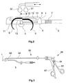
- Figures 1 and 2 show a schematic representation of a bipolar epicardial electrode for a cardiac stimulation device as a first embodiment for the epicardial electrode according to the invention.
- Fig. 1 shows the electrode in supervision, while Fig. 2 shows the electrode in a vertical section.
- the electrode comprises an electrode body 1, for example made of silicone, which is arranged at the distal end of an electrode line 3 and the underside of which Forms stimulation surface 4 of the epicardial electrode with a different pole 5.
- the stimulation signals to the heart.
- the Different pole 5 via an electrical line running through the electrode line 3 6 connected to the stimulation device.
- the indifferent pole 7 is in the embodiment shown as an annular electrode surface on the electrode line 3 arranged.
- the electrode shown in FIGS. 1 and 2 is a bipolar electrode formed, but it can also be designed as a unipolar electrode. In this In this case, there is no indifferent pole 7 on the electrode line. Instead serves then z. B. the housing of the stimulation device or a patch electrode as indifferent pole.
- the epicardial electrode according to the invention comprises four claws 9 as fixing elements (two of which can be seen in Fig. 2), which are opposite one another in pairs are arranged in channels 11 of the electrode body 1.
- the claws 9 can be move along these channels 11 between two end positions, the claws in the one end position, which is shown in Fig. 2, from the electrode body are extended so that their claw tips protrude beyond the stimulation surface 4.
- Eyes 13 are arranged at the end of the claws 9 opposite the claw tips, the sections of the channels running parallel to the stimulation surface are located and the engagement of balls 51, 52 of an introducer 50, which as Actuating elements for actuating the claws allow. Every pair of claws a common eyelet is assigned.
- the claws 9 By moving the balls 51, 52 against one another parallel to the stimulation surface 4 the claws 9 can be retracted and extended. In particular, they can be made from one State in which they are completely within the channels 11, in the extended Bring condition. The condition in which the claws are completely inside the Channels are arranged is by the corresponding end position shown in dashed lines the eyelets 13 'indicated. If the stimulation surface 4 on the heart muscle is present, the claws 9 penetrate into the heart tissue as they extend and anchor them in this way the electrode.
- an additional fixation of the epicardium electrode on the Heart tissue allows is a medical on the underside of the stimulation surface 4 Dacron fabric 14 arranged (not shown in Fig. 2), the one Allows the electrode to adhere to the heart tissue.
- pole 5 is equipped with a steroid reservoir his. The steroid is used to reduce inflammation that occurs when the claws are inserted inhibit the heart tissue.
- the electrode does include fixing elements four claws 9, which lie opposite one another in pairs in the electrode body 1 are arranged, however, any number of fixing elements can be used come.
- the number of fixing elements can, for example, depend on the size the stimulation area or the degree of fixation desired.
- FIG. 3 shows schematically an embodiment for the introducer 50 for Introducing the epicardial electrode according to the invention into the body.
- the Introducer 50 includes a hollow tube 54, one at its distal end Engagement in the eyelets 13 of the claws 9 configured ball 51 is fixed.
- a rod 56 which is in relation to the hollow tube 54 in Can be moved longitudinally.
- a second one designed to engage in the eyelets 13 of the claws 52.
- a handle 58 with two handle parts 60, 62 arranged.
- the two handle parts 60, 62 can be pivoted in this way via a joint 64 arranged to each other and connected to the rod 56 or the tube 54 that itself the balls 51, 52 move towards each other when the two handle parts 60, 62 towards each other to be pivoted, and the two balls 51, 52 away from each other move when the two handle parts 60, 62 are pivoted away from each other.
- the Balls 51, 52, tube 54, rod 56 and handle 58 together form one Actuating mechanism for retracting and extending the claws 9.
- the introducer 50 also serves for placement the electrode, which, for example, by means of the balls 51, 52 on the insertion device 50 is held. Once the electrode is placed in the right place on the heart, it can be attached using the operating mechanism. After this Extending the claws 9, the introducer 50 is removed again.
- the top of the Electrode body 1 two extending in the direction of displacement of the eyelets 13 Have slots or elongated holes, where the eyes 13 in the extended State of the claws 9 are so widened that the balls 51, 52 only on this point, i.e. when the claws are extended, through the slots or Slots can pass through.
- the Balls 51, 52 are inserted into the eyelets 13 when the claws are extended, and then the claws are retracted by actuating the actuating mechanism. there the balls 51, 52 get into those sections of the slots or elongated holes that do not allow balls 51, 52 to pass through. Only after extending the The balls 51, 52 can be clawed, i.e. after the electrode has been fixed pull out of the eyelets 13.
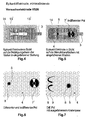
- FIGs 4 to 7 show a second embodiment of the invention Epicardium electrode
- FIG. 4 a view of the electrode body 1
- FIG. 5 show a view of the stimulation surface 4.
- Figure 6 shows an enlarged Representation of a section of the stimulation surface 4, the different and includes indifferent pole 5 or 7 'of the epicardial electrode. 7 is the stimulation area 4 in one showing the different pole 5 and the extended claws 9 shown enlarged view.
- Features of the second embodiment, the do not differ from those of the first embodiment, are with the same reference numerals as in the first embodiment.
- the second embodiment differs from the first only in that the indifferent pole 7 ′ does not form an annular electrode surface on the electrode line 3 is arranged, but just like the different pole 5 on the stimulation surface 4. This allows good contact between the indifferent pole 7 'and the Achieve heart tissue.
- arranging the indifferent increases Electrode 7 'on the stimulation surface 4 because of the distance between the indifferent and the different pole can be approximately 10 mm or more.
- the electrode body 1 is approximately 4.6 mm high, approximately 10 mm wide and approx. 25 mm long.
- the area of the arranged on the stimulation area Dacron fabric is approx. 14 mm x 32 mm.
- the claws 9 can be made of wire, for example, and typically have a diameter of about 0.2 mm.
- the channels for the claws 9 in the electrode body 1 then typically have a diameter of approximately 0.4 mm.
- the differente and the indifferent pole typically have a diameter of approx. 1.8 mm or 4.0 mm, the thickness of the different pole approximately 0.6 mm and that of the indifferent pole is approximately 0.3 mm.
- a steroid reservoir is located in the center of the different pole 8 with a diameter of approx. 1.0 mm, which contains approx. 1 mg of a steroid, e.g. Dexamethasone phosphate.
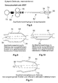
- Figure 8 shows a second embodiment of the invention Introducer.
- the introducer 50 'according to the second embodiment corresponds in principle to that of the first embodiment.
- Features of the introducer according to the second embodiment, which differ from do not differ from those of the first embodiment are in both embodiments with the same reference numerals.
- the second embodiment includes the handle 68 of the actuator to each other Move the balls not two swiveling handle parts but instead two mutually displaceable handle parts 70, 72.
- the introducer also includes 50 'of the second exemplary embodiment, two holding clips 74, 76 for holding the electrode during the insertion and fixing process.
- the retaining clips 74, 76 can optionally in a device provided on the handle 68 in a closed position, in which they have an electrode at the distal end of the introducer hold, or in an open position in which the electrode is not held become.
- Figures 9 and 10 show the distal end of the introducer 50 'in the Configuration that it with extended claws of the electrode and with closed Holding clips 74, 75 has.
- Figure 11 shows the distal end of the introducer however, with the claws retracted and the holding clips 74, 76 open.
- the introducer 50 ' is in accordance with the second exemplary embodiment with closed retaining clips 74, 76 and from retaining clips 74, 76 epicardial electrode shown.
- To hold the epicardial electrode securely to be supported by the retaining clips 74, 76 are in the side walls of the Electrode body 1 grooves 16 into which the retaining clips 74, 76 in intervene closed state.
- 12 to 14 the electrode and the distal end of the introducer 50 'from different angles extended claws 9 and closed retaining clips 74, 76 show the FIGS. 15 and 16 show the electrode and the distal end of the insertion set 50 ' retracted claws 9 and closed retaining clips 74, 76.
- the actuators instead of as balls simple pins suitable for engaging in the eyelets 13 of the claws 9 of the electrode to train because the actuators do not have a holding function for the electrode need.
Landscapes
- Health & Medical Sciences (AREA)
- Heart & Thoracic Surgery (AREA)
- Cardiology (AREA)
- Engineering & Computer Science (AREA)
- Biomedical Technology (AREA)
- Nuclear Medicine, Radiotherapy & Molecular Imaging (AREA)
- Radiology & Medical Imaging (AREA)
- Life Sciences & Earth Sciences (AREA)
- Animal Behavior & Ethology (AREA)
- General Health & Medical Sciences (AREA)
- Public Health (AREA)
- Veterinary Medicine (AREA)
- Electrotherapy Devices (AREA)
Applications Claiming Priority (2)
| Application Number | Priority Date | Filing Date | Title |
|---|---|---|---|
| DE10323016A DE10323016A1 (de) | 2003-05-15 | 2003-05-15 | Epicard-Elektrode |
| DE10323016 | 2003-05-15 |
Publications (3)
| Publication Number | Publication Date |
|---|---|
| EP1477203A2 true EP1477203A2 (fr) | 2004-11-17 |
| EP1477203A3 EP1477203A3 (fr) | 2005-03-16 |
| EP1477203B1 EP1477203B1 (fr) | 2015-09-02 |
Family
ID=33016448
Family Applications (1)
| Application Number | Title | Priority Date | Filing Date |
|---|---|---|---|
| EP04090173.8A Expired - Lifetime EP1477203B1 (fr) | 2003-05-15 | 2004-05-05 | Electrode épicardique |
Country Status (3)
| Country | Link |
|---|---|
| US (1) | US7085606B2 (fr) |
| EP (1) | EP1477203B1 (fr) |
| DE (1) | DE10323016A1 (fr) |
Cited By (3)
| Publication number | Priority date | Publication date | Assignee | Title |
|---|---|---|---|---|
| US11103280B2 (en) | 2012-12-10 | 2021-08-31 | Nevro Corp. | Lead insertion devices and associated systems and methods |
| US11389647B2 (en) | 2020-02-03 | 2022-07-19 | Nevro Corp. | Neurological stimulation lead anchors and associated tools, and methods |
| US11420045B2 (en) | 2018-03-29 | 2022-08-23 | Nevro Corp. | Leads having sidewall openings, and associated systems and methods |
Families Citing this family (123)
| Publication number | Priority date | Publication date | Assignee | Title |
|---|---|---|---|---|
| US8068920B2 (en) | 2006-10-03 | 2011-11-29 | Vincent A Gaudiani | Transcoronary sinus pacing system, LV summit pacing, early mitral closure pacing, and methods therefor |
| US10166066B2 (en) | 2007-03-13 | 2019-01-01 | University Of Virginia Patent Foundation | Epicardial ablation catheter and method of use |
| WO2008118737A1 (fr) | 2007-03-22 | 2008-10-02 | University Of Virginia Patent Foundation | Cathéter à électrode permettant d'effectuer une ablation et procédé associé |
| US9468396B2 (en) | 2007-03-19 | 2016-10-18 | University Of Virginia Patent Foundation | Systems and methods for determining location of an access needle in a subject |
| US11058354B2 (en) | 2007-03-19 | 2021-07-13 | University Of Virginia Patent Foundation | Access needle with direct visualization and related methods |
| WO2008115745A2 (fr) | 2007-03-19 | 2008-09-25 | University Of Virginia Patent Foundation | Dispositif de détection de pression d'aiguille d'accès et son procédé d'utilisation |
| EP2170458A1 (fr) * | 2007-06-13 | 2010-04-07 | E- Pacing, Inc. | Dispositifs implantables et procédés destinés à stimuler des tissus cardiaques ou d'autres tissus |
| US20100241185A1 (en) | 2007-11-09 | 2010-09-23 | University Of Virginia Patent Foundation | Steerable epicardial pacing catheter system placed via the subxiphoid process |
| US8594809B2 (en) * | 2008-04-25 | 2013-11-26 | Medtronic, Inc. | Passive fixation medical electrical lead |
| US8195297B2 (en) * | 2008-10-13 | 2012-06-05 | E-Pacing, Inc. | Devices and methods for electrical stimulation of the diaphragm and nerves |
| US9642534B2 (en) | 2009-09-11 | 2017-05-09 | University Of Virginia Patent Foundation | Systems and methods for determining location of an access needle in a subject |
| EP2537149B1 (fr) | 2010-02-18 | 2017-10-25 | University Of Virginia Patent Foundation | Système, procédé et produit programme d'ordinateur pour la simulation de procédures d'électrophysiologie épicardiques |
| US20110218604A1 (en) * | 2010-03-02 | 2011-09-08 | Sen Ji | Cardiac Lead for Epicardial, Endocardial and Trans-Coronary Sinus Placement |
| US10071243B2 (en) | 2013-07-31 | 2018-09-11 | Medtronic, Inc. | Fixation for implantable medical devices |
| US9480850B2 (en) | 2013-08-16 | 2016-11-01 | Cardiac Pacemakers, Inc. | Leadless cardiac pacemaker and retrieval device |
| US10842993B2 (en) | 2013-08-16 | 2020-11-24 | Cardiac Pacemakers, Inc. | Leadless cardiac pacing devices |
| WO2015023474A1 (fr) | 2013-08-16 | 2015-02-19 | Cardiac Pacemakers, Inc. | Stimulateur cardiaque sans fil et dispositif de récupération |
| EP3033146B1 (fr) | 2013-08-16 | 2018-03-07 | Cardiac Pacemakers, Inc. | Dispositif d'administration destinés à des dispositifs cardiaques sans conducteur |
| US9492674B2 (en) | 2013-08-16 | 2016-11-15 | Cardiac Pacemakers, Inc. | Leadless cardiac pacemaker with delivery and/or retrieval features |
| US10722723B2 (en) | 2013-08-16 | 2020-07-28 | Cardiac Pacemakers, Inc. | Delivery devices and methods for leadless cardiac devices |
| RU2661754C2 (ru) | 2013-08-16 | 2018-07-19 | Кардиак Пейсмейкерз, Инк. | Устройства кардиостимуляции без проводов |
| US9393427B2 (en) | 2013-08-16 | 2016-07-19 | Cardiac Pacemakers, Inc. | Leadless cardiac pacemaker with delivery and/or retrieval features |
| US20150196769A1 (en) | 2014-01-10 | 2015-07-16 | Cardiac Pacemakers, Inc. | Methods and systems for improved communication between medical devices |
| AU2015204701B2 (en) | 2014-01-10 | 2018-03-15 | Cardiac Pacemakers, Inc. | Systems and methods for detecting cardiac arrhythmias |
| US10080887B2 (en) | 2014-04-29 | 2018-09-25 | Cardiac Pacemakers, Inc. | Leadless cardiac pacing devices including tissue engagement verification |
| WO2015168155A1 (fr) | 2014-04-29 | 2015-11-05 | Cardiac Pacemakers, Inc. | Stimulateur cardiaque sans fil à caractéristiques permettant son extraction |
| US9526909B2 (en) | 2014-08-28 | 2016-12-27 | Cardiac Pacemakers, Inc. | Medical device with triggered blanking period |
| EP3827877B1 (fr) | 2015-02-06 | 2024-06-19 | Cardiac Pacemakers, Inc. | Systèmes de traitement d'arythmies cardiaques |
| ES2713231T3 (es) | 2015-02-06 | 2019-05-20 | Cardiac Pacemakers Inc | Sistemas para el suministro seguro de una terapia de estimulación eléctrica |
| WO2016130477A2 (fr) | 2015-02-09 | 2016-08-18 | Cardiac Pacemakers, Inc. | Dispositif médical implantable comportant une étiquette d'identification radio-opaque |
| EP3265172B1 (fr) | 2015-03-04 | 2018-12-19 | Cardiac Pacemakers, Inc. | Systèmes de traitement d'arythmies cardiaques |
| CN107427222B (zh) | 2015-03-18 | 2021-02-09 | 心脏起搏器股份公司 | 使用链路质量评估的医疗设备系统中的通信 |
| US10050700B2 (en) | 2015-03-18 | 2018-08-14 | Cardiac Pacemakers, Inc. | Communications in a medical device system with temporal optimization |
| US9853743B2 (en) | 2015-08-20 | 2017-12-26 | Cardiac Pacemakers, Inc. | Systems and methods for communication between medical devices |
| WO2017031347A1 (fr) | 2015-08-20 | 2017-02-23 | Cardiac Pacemakers, Inc. | Systèmes et procédés de communication entre des dispositifs médicaux |
| US9956414B2 (en) | 2015-08-27 | 2018-05-01 | Cardiac Pacemakers, Inc. | Temporal configuration of a motion sensor in an implantable medical device |
| US9968787B2 (en) | 2015-08-27 | 2018-05-15 | Cardiac Pacemakers, Inc. | Spatial configuration of a motion sensor in an implantable medical device |
| WO2017040115A1 (fr) | 2015-08-28 | 2017-03-09 | Cardiac Pacemakers, Inc. | Système de détection de tamponnade |
| US10137305B2 (en) | 2015-08-28 | 2018-11-27 | Cardiac Pacemakers, Inc. | Systems and methods for behaviorally responsive signal detection and therapy delivery |
| US10226631B2 (en) | 2015-08-28 | 2019-03-12 | Cardiac Pacemakers, Inc. | Systems and methods for infarct detection |
| WO2017044389A1 (fr) | 2015-09-11 | 2017-03-16 | Cardiac Pacemakers, Inc. | Détection et confirmation d'arythmie |
| US10065041B2 (en) | 2015-10-08 | 2018-09-04 | Cardiac Pacemakers, Inc. | Devices and methods for adjusting pacing rates in an implantable medical device |
| US10631840B2 (en) | 2015-11-25 | 2020-04-28 | Talon Medical, LLC | Tissue engagement devices, systems, and methods |
| JP6608063B2 (ja) | 2015-12-17 | 2019-11-20 | カーディアック ペースメイカーズ, インコーポレイテッド | 植込み型医療装置 |
| US10905886B2 (en) | 2015-12-28 | 2021-02-02 | Cardiac Pacemakers, Inc. | Implantable medical device for deployment across the atrioventricular septum |
| WO2017127548A1 (fr) | 2016-01-19 | 2017-07-27 | Cardiac Pacemakers, Inc. | Dispositifs permettant de recharger sans fil une batterie rechargeable d'un dispositif médical implantable |
| US10099050B2 (en) | 2016-01-21 | 2018-10-16 | Medtronic, Inc. | Interventional medical devices, device systems, and fixation components thereof |
| US10463853B2 (en) | 2016-01-21 | 2019-11-05 | Medtronic, Inc. | Interventional medical systems |
| WO2017136548A1 (fr) | 2016-02-04 | 2017-08-10 | Cardiac Pacemakers, Inc. | Système de pose avec capteur de force pour dispositif cardiaque sans fil |
| US11116988B2 (en) | 2016-03-31 | 2021-09-14 | Cardiac Pacemakers, Inc. | Implantable medical device with rechargeable battery |
| US10328272B2 (en) | 2016-05-10 | 2019-06-25 | Cardiac Pacemakers, Inc. | Retrievability for implantable medical devices |
| US10668294B2 (en) | 2016-05-10 | 2020-06-02 | Cardiac Pacemakers, Inc. | Leadless cardiac pacemaker configured for over the wire delivery |
| JP6764956B2 (ja) | 2016-06-27 | 2020-10-07 | カーディアック ペースメイカーズ, インコーポレイテッド | 再同期ペーシング管理に皮下で感知されたp波を使用する心臓治療法システム |
| US11207527B2 (en) | 2016-07-06 | 2021-12-28 | Cardiac Pacemakers, Inc. | Method and system for determining an atrial contraction timing fiducial in a leadless cardiac pacemaker system |
| WO2018009392A1 (fr) | 2016-07-07 | 2018-01-11 | Cardiac Pacemakers, Inc. | Stimulateur cardiaque sans fil utilisant des mesures de pression pour la vérification de la capture de stimulation |
| CN109475743B (zh) | 2016-07-20 | 2022-09-02 | 心脏起搏器股份公司 | 在无引线心脏起搏器系统中利用心房收缩定时基准的系统 |
| WO2018035343A1 (fr) | 2016-08-19 | 2018-02-22 | Cardiac Pacemakers, Inc. | Dispositif médical implantable trans-septal |
| EP3503970B1 (fr) | 2016-08-24 | 2023-01-04 | Cardiac Pacemakers, Inc. | Resynchronisation cardiaque utilisant l'encouragement de la fusion pour la gestion de la synchronisation |
| CN109640809B (zh) | 2016-08-24 | 2021-08-17 | 心脏起搏器股份公司 | 使用p波到起搏定时的集成式多装置心脏再同步治疗 |
| US10758737B2 (en) | 2016-09-21 | 2020-09-01 | Cardiac Pacemakers, Inc. | Using sensor data from an intracardially implanted medical device to influence operation of an extracardially implantable cardioverter |
| WO2018057626A1 (fr) | 2016-09-21 | 2018-03-29 | Cardiac Pacemakers, Inc. | Moniteur cardiaque implantable |
| WO2018057318A1 (fr) | 2016-09-21 | 2018-03-29 | Cardiac Pacemakers, Inc. | Dispositif de stimulation sans fil muni d'un boîtier qui abrite des composants interne du dispositif de stimulation sans fil et fonctionne comme boîtier de batterie et borne d'une batterie interne |
| US10238865B2 (en) | 2016-10-06 | 2019-03-26 | Medtronic, Inc. | Electrode fixation in interventional medical systems |
| AU2017350759B2 (en) | 2016-10-27 | 2019-10-17 | Cardiac Pacemakers, Inc. | Implantable medical device with pressure sensor |
| US10328257B2 (en) * | 2016-10-27 | 2019-06-25 | Medtronic, Inc. | Electrode fixation in interventional medical systems |
| WO2018081237A1 (fr) | 2016-10-27 | 2018-05-03 | Cardiac Pacemakers, Inc. | Utilisation d'un dispositif séparé pour gérer l'énergie d'impulsion de stimulation d'un stimulateur cardiaque |
| WO2018081133A1 (fr) | 2016-10-27 | 2018-05-03 | Cardiac Pacemakers, Inc. | Dispositif médical implantable présentant un canal d'écoute à réglage de rendement |
| US10758724B2 (en) | 2016-10-27 | 2020-09-01 | Cardiac Pacemakers, Inc. | Implantable medical device delivery system with integrated sensor |
| US10413733B2 (en) | 2016-10-27 | 2019-09-17 | Cardiac Pacemakers, Inc. | Implantable medical device with gyroscope |
| WO2018081275A1 (fr) | 2016-10-27 | 2018-05-03 | Cardiac Pacemakers, Inc. | Thérapie de resynchronisation cardiaque à dispositifs multiples avec des améliorations de synchronisation |
| EP3532157B1 (fr) | 2016-10-31 | 2020-08-26 | Cardiac Pacemakers, Inc. | Systèmes de stimulation de niveau d'activité |
| US10434317B2 (en) | 2016-10-31 | 2019-10-08 | Cardiac Pacemakers, Inc. | Systems and methods for activity level pacing |
| WO2018089311A1 (fr) | 2016-11-08 | 2018-05-17 | Cardiac Pacemakers, Inc | Dispositif médical implantable pour déploiement auriculaire |
| WO2018089308A1 (fr) | 2016-11-09 | 2018-05-17 | Cardiac Pacemakers, Inc. | Systèmes, dispositifs et procédés pour régler des paramètres d'impulsion de stimulation cardiaque pour un dispositif de stimulation cardiaque |
| EP3541473B1 (fr) | 2016-11-21 | 2020-11-11 | Cardiac Pacemakers, Inc. | Stimulateur cardiaque sans sonde à communication multimodale |
| EP3541472B1 (fr) | 2016-11-21 | 2023-06-07 | Cardiac Pacemakers, Inc. | Dispositif médical implantable comportant un boîtier magnétiquement perméable et une bobine inductive placée autour du boîtier |
| CN109982746B (zh) | 2016-11-21 | 2023-04-04 | 心脏起搏器股份公司 | 提供心脏再同步治疗的无引线心脏起搏器 |
| US10639486B2 (en) | 2016-11-21 | 2020-05-05 | Cardiac Pacemakers, Inc. | Implantable medical device with recharge coil |
| US10881869B2 (en) | 2016-11-21 | 2021-01-05 | Cardiac Pacemakers, Inc. | Wireless re-charge of an implantable medical device |
| US11207532B2 (en) | 2017-01-04 | 2021-12-28 | Cardiac Pacemakers, Inc. | Dynamic sensing updates using postural input in a multiple device cardiac rhythm management system |
| CN110198759B (zh) | 2017-01-26 | 2023-08-11 | 心脏起搏器股份公司 | 具有可拆卸固定件的无引线可植入装置 |
| JP7000438B2 (ja) | 2017-01-26 | 2022-01-19 | カーディアック ペースメイカーズ, インコーポレイテッド | 冗長メッセージ送信を伴う人体デバイス通信 |
| CN110234392B (zh) | 2017-01-26 | 2023-08-11 | 心脏起搏器股份公司 | 具有被包覆模制的组件的无引线装置 |
| US10905872B2 (en) | 2017-04-03 | 2021-02-02 | Cardiac Pacemakers, Inc. | Implantable medical device with a movable electrode biased toward an extended position |
| US10821288B2 (en) | 2017-04-03 | 2020-11-03 | Cardiac Pacemakers, Inc. | Cardiac pacemaker with pacing pulse energy adjustment based on sensed heart rate |
| WO2019036568A1 (fr) | 2017-08-18 | 2019-02-21 | Cardiac Pacemakers, Inc. | Dispositif médical implantable comprenant un concentrateur de flux et une bobine de réception disposée autour du concentrateur de flux |
| EP3668592B1 (fr) | 2017-08-18 | 2021-11-17 | Cardiac Pacemakers, Inc. | Dispositif médical implantable avec capteur de pression |
| JP6938778B2 (ja) | 2017-09-20 | 2021-09-22 | カーディアック ペースメイカーズ, インコーポレイテッド | 複数の作動モードを備えた移植式医療用装置 |
| US11185703B2 (en) | 2017-11-07 | 2021-11-30 | Cardiac Pacemakers, Inc. | Leadless cardiac pacemaker for bundle of his pacing |
| EP3717063B1 (fr) | 2017-12-01 | 2023-12-27 | Cardiac Pacemakers, Inc. | Systèmes pour détecter des repères de synchronisation de contraction auriculaire et pour déterminer un intervalle cardiaque à partir d'un stimulateur cardiaque sans fil implanté de manière ventriculaire |
| EP3717060B1 (fr) | 2017-12-01 | 2022-10-05 | Cardiac Pacemakers, Inc. | Stimulateur cardiaque sans fil à comportement réversible |
| EP3717059B1 (fr) | 2017-12-01 | 2024-11-20 | Cardiac Pacemakers, Inc. | Systèmes pour détecter des repères de synchronisation de contraction auriculaire dans une fenêtre de recherche à partir d'un stimulateur cardiaque sans fil implanté de manière ventriculaire |
| WO2019108545A1 (fr) | 2017-12-01 | 2019-06-06 | Cardiac Pacemakers, Inc. | Procédés et systèmes pour détecter des repères de synchronisation de contraction auriculaire pendant un remplissage ventriculaire à partir d'un stimulateur cardiaque sans fil implanté de manière ventriculaire |
| US11529523B2 (en) | 2018-01-04 | 2022-12-20 | Cardiac Pacemakers, Inc. | Handheld bridge device for providing a communication bridge between an implanted medical device and a smartphone |
| EP3735293B1 (fr) | 2018-01-04 | 2022-03-09 | Cardiac Pacemakers, Inc. | Stimulation double chambre sans communication battement à battement |
| JP2021518192A (ja) | 2018-03-23 | 2021-08-02 | メドトロニック,インコーポレイテッド | VfA心臓再同期治療 |
| EP3768369A1 (fr) | 2018-03-23 | 2021-01-27 | Medtronic, Inc. | Thérapie cardiaque du ventricule vers l'atrium (vfa) synchrone atrioventriculaire (av) |
| US11058880B2 (en) | 2018-03-23 | 2021-07-13 | Medtronic, Inc. | VFA cardiac therapy for tachycardia |
| US10576291B2 (en) | 2018-07-31 | 2020-03-03 | Manicka Institute Llc | Subcutaneous device |
| US11179571B2 (en) | 2018-07-31 | 2021-11-23 | Manicka Institute Llc | Subcutaneous device for monitoring and/or providing therapies |
| US11660444B2 (en) | 2018-07-31 | 2023-05-30 | Manicka Institute Llc | Resilient body component contact for a subcutaneous device |
| US11433233B2 (en) | 2020-11-25 | 2022-09-06 | Calyan Technologies, Inc. | Electrode contact for a subcutaneous device |
| US10716511B2 (en) | 2018-07-31 | 2020-07-21 | Manicka Institute Llc | Subcutaneous device for monitoring and/or providing therapies |
| US11717674B2 (en) | 2018-07-31 | 2023-08-08 | Manicka Institute Llc | Subcutaneous device for use with remote device |
| EP3856331A1 (fr) | 2018-09-26 | 2021-08-04 | Medtronic, Inc. | Capture dans une thérapie cardiaque du ventricule à partir de l'oreillette |
| US11648397B1 (en) | 2018-10-12 | 2023-05-16 | Vincent Gaudiani | Transcoronary sinus pacing of posteroseptal left ventricular base |
| US11577075B1 (en) | 2018-10-12 | 2023-02-14 | Vincent A. Gaudiani | Transcoronary sinus pacing of his bundle |
| US11951313B2 (en) | 2018-11-17 | 2024-04-09 | Medtronic, Inc. | VFA delivery systems and methods |
| EP3897816B1 (fr) | 2018-12-21 | 2024-03-27 | Medtronic, Inc. | Systèmes de pose pour stimulation ventriculaire gauche |
| US11679265B2 (en) | 2019-02-14 | 2023-06-20 | Medtronic, Inc. | Lead-in-lead systems and methods for cardiac therapy |
| US11759632B2 (en) | 2019-03-28 | 2023-09-19 | Medtronic, Inc. | Fixation components for implantable medical devices |
| US11697025B2 (en) | 2019-03-29 | 2023-07-11 | Medtronic, Inc. | Cardiac conduction system capture |
| US11213676B2 (en) | 2019-04-01 | 2022-01-04 | Medtronic, Inc. | Delivery systems for VfA cardiac therapy |
| US11712188B2 (en) | 2019-05-07 | 2023-08-01 | Medtronic, Inc. | Posterior left bundle branch engagement |
| US11305127B2 (en) | 2019-08-26 | 2022-04-19 | Medtronic Inc. | VfA delivery and implant region detection |
| US11813466B2 (en) | 2020-01-27 | 2023-11-14 | Medtronic, Inc. | Atrioventricular nodal stimulation |
| US12543992B2 (en) | 2020-03-30 | 2026-02-10 | Medtronic, Inc. | Pacing efficacy determination using a representative morphology of external cardiac signals |
| US11911168B2 (en) | 2020-04-03 | 2024-02-27 | Medtronic, Inc. | Cardiac conduction system therapy benefit determination |
| US12605103B2 (en) | 2020-05-21 | 2026-04-21 | Medtronic, Inc. | QRS detection and bracketing |
| US12465770B2 (en) | 2020-07-31 | 2025-11-11 | Medtronic, Inc. | Coronary sinus conduction system pacing and delivery |
| US11813464B2 (en) | 2020-07-31 | 2023-11-14 | Medtronic, Inc. | Cardiac conduction system evaluation |
| US10987060B1 (en) | 2020-09-14 | 2021-04-27 | Calyan Technologies, Inc. | Clip design for a subcutaneous device |
| US12502531B2 (en) | 2021-04-26 | 2025-12-23 | Manicka Institute Llc | Subcutaneous device for preventing and treating atherosclerosis |
Citations (1)
| Publication number | Priority date | Publication date | Assignee | Title |
|---|---|---|---|---|
| US5683447A (en) | 1995-12-19 | 1997-11-04 | Ventritex, Inc. | Lead with septal defibrillation and pacing electrodes |
Family Cites Families (16)
| Publication number | Priority date | Publication date | Assignee | Title |
|---|---|---|---|---|
| US4144890A (en) * | 1975-01-14 | 1979-03-20 | Cordis Corporation | Contact device for muscle stimulation |
| US3999555A (en) * | 1975-10-28 | 1976-12-28 | Medtronic, Inc. | Atrial pinch on lead and insertion tool |
| US4142530A (en) * | 1978-03-06 | 1979-03-06 | Vitatron Medical B. V. | Epicardial lead |
| US4235246A (en) * | 1979-02-05 | 1980-11-25 | Arco Medical Products Company | Epicardial heart lead and assembly and method for optimal fixation of same for cardiac pacing |
| US4282886A (en) * | 1979-11-13 | 1981-08-11 | Medtronic, Inc. | Adhesive bonded positive fixation epicardial lead |
| US4357946A (en) * | 1980-03-24 | 1982-11-09 | Medtronic, Inc. | Epicardial pacing lead with stylet controlled helical fixation screw |
| US4424818A (en) * | 1982-02-18 | 1984-01-10 | Medtronic, Inc. | Electrical lead and insertion tool |
| EP0134367A1 (fr) * | 1983-08-12 | 1985-03-20 | Jean-Pierre Alfandari | Dispositif de stimulation cardiaque comprenant une électrode épicardique distincte d'un moyen de fixation |
| USH356H (en) * | 1985-02-27 | 1987-11-03 | Medtronic, Inc. | Epicardial lead having low threshold, low polarization myocardial electrode |
| US4607644A (en) * | 1985-04-01 | 1986-08-26 | Cordis Corporation | Self-suturing porous epicardial electrode assembly |
| US5314462A (en) * | 1992-05-27 | 1994-05-24 | Cardiac Pacemakers, Inc. | Positive fixation device |
| US5304203A (en) * | 1992-10-20 | 1994-04-19 | Numed Technologies, Inc. | Tissue extracting forceps for laparoscopic surgery |
| US5545207A (en) * | 1994-08-24 | 1996-08-13 | Medtronic, Inc. | Medical electrical lead having stable fixation system |
| US5630831A (en) * | 1995-05-04 | 1997-05-20 | Lahr; Christopher J. | Fingerlike medical instruments for use in laparoscopic procedures |
| US5871532A (en) * | 1997-05-22 | 1999-02-16 | Sulzer Intermedics Inc. | Epicardial lead for minimally invasive implantation |
| SE0201320D0 (sv) * | 2002-04-30 | 2002-04-30 | St Jude Medical | Epicardial pacing lead arrangement |
-
2003
- 2003-05-15 DE DE10323016A patent/DE10323016A1/de not_active Withdrawn
-
2004
- 2004-05-05 EP EP04090173.8A patent/EP1477203B1/fr not_active Expired - Lifetime
- 2004-05-14 US US10/845,686 patent/US7085606B2/en not_active Expired - Lifetime
Patent Citations (1)
| Publication number | Priority date | Publication date | Assignee | Title |
|---|---|---|---|---|
| US5683447A (en) | 1995-12-19 | 1997-11-04 | Ventritex, Inc. | Lead with septal defibrillation and pacing electrodes |
Cited By (4)
| Publication number | Priority date | Publication date | Assignee | Title |
|---|---|---|---|---|
| US11103280B2 (en) | 2012-12-10 | 2021-08-31 | Nevro Corp. | Lead insertion devices and associated systems and methods |
| US11420045B2 (en) | 2018-03-29 | 2022-08-23 | Nevro Corp. | Leads having sidewall openings, and associated systems and methods |
| US11389647B2 (en) | 2020-02-03 | 2022-07-19 | Nevro Corp. | Neurological stimulation lead anchors and associated tools, and methods |
| US12214188B2 (en) | 2020-02-03 | 2025-02-04 | Nevro Corp. | Neurological stimulation lead anchors and associated tools, and methods |
Also Published As
| Publication number | Publication date |
|---|---|
| EP1477203B1 (fr) | 2015-09-02 |
| US7085606B2 (en) | 2006-08-01 |
| US20040267343A1 (en) | 2004-12-30 |
| EP1477203A3 (fr) | 2005-03-16 |
| DE10323016A1 (de) | 2004-12-02 |
Similar Documents
| Publication | Publication Date | Title |
|---|---|---|
| EP1477203B1 (fr) | Electrode épicardique | |
| DE69628663T2 (de) | Minimalinvasive, medizinische, elektrische leitung | |
| DE69213336T2 (de) | Werkzeug zur Einführung und Tunnelung für subkutane Drahtgeflecht-Elektroden | |
| DE2506694C2 (de) | Implantierbare, transvenös einführbare Elektrodenanordnung | |
| DE69514126T2 (de) | Durch Nähen permanent implantierte Elektrode zum Eluieren von Medikamenten | |
| DE69525125T2 (de) | Medizinischer elektrischer Leiter mit verstärkten Zinken | |
| DE69200527T2 (de) | Abnehmbare endocardiale leitung. | |
| DE60311487T2 (de) | Zuführsystem für medizinische vorrichtungen | |
| DE4335098B4 (de) | Elektrodenzuleitung mit Halteelement für einen Führungsstab und deren Verwendung | |
| DE69029564T2 (de) | Geflochtene Elektrodenleitungen und Katheter für ihre Benutzung | |
| DE69826546T2 (de) | Medizinische elektrische Leitung | |
| EP2589348B1 (fr) | Dispositif destiné à l'explantation de dérivations d'électrodes | |
| DE2643956A1 (de) | Elektrodensystem zur behandlung des herzkammerflatterns und verfahren zu seiner anwendung | |
| EP2123323B1 (fr) | Fil d'électrode implantable | |
| DE60013893T2 (de) | System und elektrode zur perkutanen elektrischen therapie | |
| DE69009193T2 (de) | Steroideluierende intramuskuläre leitung. | |
| EP0951920A2 (fr) | Electrode destinée à être fixée à la paroi d'un vaisseau | |
| DE60114291T2 (de) | Vorrichtung zum Implantieren von einer Herzstimulationsleitung in Koronargefässen | |
| DE2743431A1 (de) | Verfahren und vorrichtung zur einpflanzung einer oder mehrerer schrittmacher-elektroden in ein herz | |
| DE10034097A1 (de) | System zum Bereitstellen medizinischer, elektrischer Stimulation an Nervengewebe | |
| DE202010017584U1 (de) | Gastrointestinale Vorrichtung | |
| DE102015223541A1 (de) | Implantierbares Fluidpumpensystem | |
| DE69328256T2 (de) | Vorrichtung zur implantierung von defibrillations-elektroden | |
| EP2767306B1 (fr) | Applicateur chirurgical d'implantation de fil d'électrode | |
| DE29909082U1 (de) | Stimulations-, Sensing- und/oder Defibrillationselektrode sowie Ballon-Katheter zum Einbringen der Elektrode |
Legal Events
| Date | Code | Title | Description |
|---|---|---|---|
| PUAI | Public reference made under article 153(3) epc to a published international application that has entered the european phase |
Free format text: ORIGINAL CODE: 0009012 |
|
| AK | Designated contracting states |
Kind code of ref document: A2 Designated state(s): AT BE BG CH CY CZ DE DK EE ES FI FR GB GR HU IE IT LI LU MC NL PL PT RO SE SI SK TR |
|
| AX | Request for extension of the european patent |
Extension state: AL HR LT LV MK |
|
| PUAL | Search report despatched |
Free format text: ORIGINAL CODE: 0009013 |
|
| AK | Designated contracting states |
Kind code of ref document: A3 Designated state(s): AT BE BG CH CY CZ DE DK EE ES FI FR GB GR HU IE IT LI LU MC NL PL PT RO SE SI SK TR |
|
| AX | Request for extension of the european patent |
Extension state: AL HR LT LV MK |
|
| 17P | Request for examination filed |
Effective date: 20050916 |
|
| AKX | Designation fees paid |
Designated state(s): AT BE BG CH CY CZ DE DK EE ES FI FR GB GR HU IE IT LI LU MC NL PL PT RO SE SI SK TR |
|
| RAP1 | Party data changed (applicant data changed or rights of an application transferred) |
Owner name: BIOTRONIK SE & CO. KG |
|
| RAP1 | Party data changed (applicant data changed or rights of an application transferred) |
Owner name: BIOTRONIK SE & CO. KG |
|
| GRAP | Despatch of communication of intention to grant a patent |
Free format text: ORIGINAL CODE: EPIDOSNIGR1 |
|
| INTG | Intention to grant announced |
Effective date: 20150528 |
|
| GRAS | Grant fee paid |
Free format text: ORIGINAL CODE: EPIDOSNIGR3 |
|
| GRAA | (expected) grant |
Free format text: ORIGINAL CODE: 0009210 |
|
| AK | Designated contracting states |
Kind code of ref document: B1 Designated state(s): AT BE BG CH CY CZ DE DK EE ES FI FR GB GR HU IE IT LI LU MC NL PL PT RO SE SI SK TR |
|
| REG | Reference to a national code |
Ref country code: GB Ref legal event code: FG4D Free format text: NOT ENGLISH |
|
| REG | Reference to a national code |
Ref country code: AT Ref legal event code: REF Ref document number: 746151 Country of ref document: AT Kind code of ref document: T Effective date: 20150915 Ref country code: CH Ref legal event code: EP |
|
| REG | Reference to a national code |
Ref country code: IE Ref legal event code: FG4D Free format text: LANGUAGE OF EP DOCUMENT: GERMAN |
|
| REG | Reference to a national code |
Ref country code: DE Ref legal event code: R096 Ref document number: 502004015012 Country of ref document: DE |
|
| PG25 | Lapsed in a contracting state [announced via postgrant information from national office to epo] |
Ref country code: GR Free format text: LAPSE BECAUSE OF FAILURE TO SUBMIT A TRANSLATION OF THE DESCRIPTION OR TO PAY THE FEE WITHIN THE PRESCRIBED TIME-LIMIT Effective date: 20151203 Ref country code: FI Free format text: LAPSE BECAUSE OF FAILURE TO SUBMIT A TRANSLATION OF THE DESCRIPTION OR TO PAY THE FEE WITHIN THE PRESCRIBED TIME-LIMIT Effective date: 20150902 |
|
| REG | Reference to a national code |
Ref country code: NL Ref legal event code: MP Effective date: 20150902 |
|
| PG25 | Lapsed in a contracting state [announced via postgrant information from national office to epo] |
Ref country code: ES Free format text: LAPSE BECAUSE OF FAILURE TO SUBMIT A TRANSLATION OF THE DESCRIPTION OR TO PAY THE FEE WITHIN THE PRESCRIBED TIME-LIMIT Effective date: 20150902 Ref country code: SE Free format text: LAPSE BECAUSE OF FAILURE TO SUBMIT A TRANSLATION OF THE DESCRIPTION OR TO PAY THE FEE WITHIN THE PRESCRIBED TIME-LIMIT Effective date: 20150902 Ref country code: PL Free format text: LAPSE BECAUSE OF FAILURE TO SUBMIT A TRANSLATION OF THE DESCRIPTION OR TO PAY THE FEE WITHIN THE PRESCRIBED TIME-LIMIT Effective date: 20150902 |
|
| PG25 | Lapsed in a contracting state [announced via postgrant information from national office to epo] |
Ref country code: NL Free format text: LAPSE BECAUSE OF FAILURE TO SUBMIT A TRANSLATION OF THE DESCRIPTION OR TO PAY THE FEE WITHIN THE PRESCRIBED TIME-LIMIT Effective date: 20150902 Ref country code: IT Free format text: LAPSE BECAUSE OF FAILURE TO SUBMIT A TRANSLATION OF THE DESCRIPTION OR TO PAY THE FEE WITHIN THE PRESCRIBED TIME-LIMIT Effective date: 20150902 Ref country code: CZ Free format text: LAPSE BECAUSE OF FAILURE TO SUBMIT A TRANSLATION OF THE DESCRIPTION OR TO PAY THE FEE WITHIN THE PRESCRIBED TIME-LIMIT Effective date: 20150902 Ref country code: SK Free format text: LAPSE BECAUSE OF FAILURE TO SUBMIT A TRANSLATION OF THE DESCRIPTION OR TO PAY THE FEE WITHIN THE PRESCRIBED TIME-LIMIT Effective date: 20150902 Ref country code: EE Free format text: LAPSE BECAUSE OF FAILURE TO SUBMIT A TRANSLATION OF THE DESCRIPTION OR TO PAY THE FEE WITHIN THE PRESCRIBED TIME-LIMIT Effective date: 20150902 |
|
| PG25 | Lapsed in a contracting state [announced via postgrant information from national office to epo] |
Ref country code: PT Free format text: LAPSE BECAUSE OF FAILURE TO SUBMIT A TRANSLATION OF THE DESCRIPTION OR TO PAY THE FEE WITHIN THE PRESCRIBED TIME-LIMIT Effective date: 20160104 Ref country code: RO Free format text: LAPSE BECAUSE OF FAILURE TO SUBMIT A TRANSLATION OF THE DESCRIPTION OR TO PAY THE FEE WITHIN THE PRESCRIBED TIME-LIMIT Effective date: 20150902 |
|
| REG | Reference to a national code |
Ref country code: DE Ref legal event code: R097 Ref document number: 502004015012 Country of ref document: DE |
|
| PLBE | No opposition filed within time limit |
Free format text: ORIGINAL CODE: 0009261 |
|
| STAA | Information on the status of an ep patent application or granted ep patent |
Free format text: STATUS: NO OPPOSITION FILED WITHIN TIME LIMIT |
|
| 26N | No opposition filed |
Effective date: 20160603 |
|
| PG25 | Lapsed in a contracting state [announced via postgrant information from national office to epo] |
Ref country code: DK Free format text: LAPSE BECAUSE OF FAILURE TO SUBMIT A TRANSLATION OF THE DESCRIPTION OR TO PAY THE FEE WITHIN THE PRESCRIBED TIME-LIMIT Effective date: 20150902 Ref country code: BE Free format text: LAPSE BECAUSE OF NON-PAYMENT OF DUE FEES Effective date: 20160531 Ref country code: SI Free format text: LAPSE BECAUSE OF FAILURE TO SUBMIT A TRANSLATION OF THE DESCRIPTION OR TO PAY THE FEE WITHIN THE PRESCRIBED TIME-LIMIT Effective date: 20150902 |
|
| PG25 | Lapsed in a contracting state [announced via postgrant information from national office to epo] |
Ref country code: LU Free format text: LAPSE BECAUSE OF FAILURE TO SUBMIT A TRANSLATION OF THE DESCRIPTION OR TO PAY THE FEE WITHIN THE PRESCRIBED TIME-LIMIT Effective date: 20160505 |
|
| GBPC | Gb: european patent ceased through non-payment of renewal fee |
Effective date: 20160505 |
|
| REG | Reference to a national code |
Ref country code: FR Ref legal event code: ST Effective date: 20170131 |
|
| PG25 | Lapsed in a contracting state [announced via postgrant information from national office to epo] |
Ref country code: FR Free format text: LAPSE BECAUSE OF NON-PAYMENT OF DUE FEES Effective date: 20160531 |
|
| PG25 | Lapsed in a contracting state [announced via postgrant information from national office to epo] |
Ref country code: GB Free format text: LAPSE BECAUSE OF NON-PAYMENT OF DUE FEES Effective date: 20160505 |
|
| REG | Reference to a national code |
Ref country code: AT Ref legal event code: MM01 Ref document number: 746151 Country of ref document: AT Kind code of ref document: T Effective date: 20160505 |
|
| PG25 | Lapsed in a contracting state [announced via postgrant information from national office to epo] |
Ref country code: AT Free format text: LAPSE BECAUSE OF NON-PAYMENT OF DUE FEES Effective date: 20160505 |
|
| PG25 | Lapsed in a contracting state [announced via postgrant information from national office to epo] |
Ref country code: CY Free format text: LAPSE BECAUSE OF FAILURE TO SUBMIT A TRANSLATION OF THE DESCRIPTION OR TO PAY THE FEE WITHIN THE PRESCRIBED TIME-LIMIT Effective date: 20150902 Ref country code: HU Free format text: LAPSE BECAUSE OF FAILURE TO SUBMIT A TRANSLATION OF THE DESCRIPTION OR TO PAY THE FEE WITHIN THE PRESCRIBED TIME-LIMIT; INVALID AB INITIO Effective date: 20040505 |
|
| PG25 | Lapsed in a contracting state [announced via postgrant information from national office to epo] |
Ref country code: TR Free format text: LAPSE BECAUSE OF FAILURE TO SUBMIT A TRANSLATION OF THE DESCRIPTION OR TO PAY THE FEE WITHIN THE PRESCRIBED TIME-LIMIT Effective date: 20150902 Ref country code: MC Free format text: LAPSE BECAUSE OF FAILURE TO SUBMIT A TRANSLATION OF THE DESCRIPTION OR TO PAY THE FEE WITHIN THE PRESCRIBED TIME-LIMIT Effective date: 20150902 |
|
| PG25 | Lapsed in a contracting state [announced via postgrant information from national office to epo] |
Ref country code: BG Free format text: LAPSE BECAUSE OF FAILURE TO SUBMIT A TRANSLATION OF THE DESCRIPTION OR TO PAY THE FEE WITHIN THE PRESCRIBED TIME-LIMIT Effective date: 20150902 |
|
| PGFP | Annual fee paid to national office [announced via postgrant information from national office to epo] |
Ref country code: DE Payment date: 20190529 Year of fee payment: 16 Ref country code: IE Payment date: 20190520 Year of fee payment: 16 |
|
| PGFP | Annual fee paid to national office [announced via postgrant information from national office to epo] |
Ref country code: CH Payment date: 20190523 Year of fee payment: 16 |
|
| REG | Reference to a national code |
Ref country code: DE Ref legal event code: R119 Ref document number: 502004015012 Country of ref document: DE |
|
| PG25 | Lapsed in a contracting state [announced via postgrant information from national office to epo] |
Ref country code: LI Free format text: LAPSE BECAUSE OF NON-PAYMENT OF DUE FEES Effective date: 20200531 Ref country code: CH Free format text: LAPSE BECAUSE OF NON-PAYMENT OF DUE FEES Effective date: 20200531 |
|
| PG25 | Lapsed in a contracting state [announced via postgrant information from national office to epo] |
Ref country code: IE Free format text: LAPSE BECAUSE OF NON-PAYMENT OF DUE FEES Effective date: 20200505 |
|
| PG25 | Lapsed in a contracting state [announced via postgrant information from national office to epo] |
Ref country code: DE Free format text: LAPSE BECAUSE OF NON-PAYMENT OF DUE FEES Effective date: 20201201 |