EP1477238B1 - Appareil pour nettoyer et/ou désinfecter des corps creux allongés, en particulier tubes médicaux et catheters - Google Patents
Appareil pour nettoyer et/ou désinfecter des corps creux allongés, en particulier tubes médicaux et catheters Download PDFInfo
- Publication number
- EP1477238B1 EP1477238B1 EP04007482A EP04007482A EP1477238B1 EP 1477238 B1 EP1477238 B1 EP 1477238B1 EP 04007482 A EP04007482 A EP 04007482A EP 04007482 A EP04007482 A EP 04007482A EP 1477238 B1 EP1477238 B1 EP 1477238B1
- Authority
- EP
- European Patent Office
- Prior art keywords
- piston
- pressure
- water channel
- sleeve
- pressure sensor
- Prior art date
- Legal status (The legal status is an assumption and is not a legal conclusion. Google has not performed a legal analysis and makes no representation as to the accuracy of the status listed.)
- Expired - Lifetime
Links
Images

Classifications
-
- B—PERFORMING OPERATIONS; TRANSPORTING
- B08—CLEANING
- B08B—CLEANING IN GENERAL; PREVENTION OF FOULING IN GENERAL
- B08B9/00—Cleaning hollow articles by methods or apparatus specially adapted thereto
- B08B9/02—Cleaning pipes or tubes or systems of pipes or tubes
- B08B9/027—Cleaning the internal surfaces; Removal of blockages
- B08B9/032—Cleaning the internal surfaces; Removal of blockages by the mechanical action of a moving fluid, e.g. by flushing
- B08B9/0321—Cleaning the internal surfaces; Removal of blockages by the mechanical action of a moving fluid, e.g. by flushing using pressurised, pulsating or purging fluid
-
- A—HUMAN NECESSITIES
- A61—MEDICAL OR VETERINARY SCIENCE; HYGIENE
- A61B—DIAGNOSIS; SURGERY; IDENTIFICATION
- A61B1/00—Instruments for performing medical examinations of the interior of cavities or tubes of the body by visual or photographical inspection, e.g. endoscopes; Illuminating arrangements therefor
- A61B1/00002—Operational features of endoscopes
- A61B1/00057—Operational features of endoscopes provided with means for testing or calibration
-
- A—HUMAN NECESSITIES
- A61—MEDICAL OR VETERINARY SCIENCE; HYGIENE
- A61B—DIAGNOSIS; SURGERY; IDENTIFICATION
- A61B1/00—Instruments for performing medical examinations of the interior of cavities or tubes of the body by visual or photographical inspection, e.g. endoscopes; Illuminating arrangements therefor
- A61B1/12—Instruments for performing medical examinations of the interior of cavities or tubes of the body by visual or photographical inspection, e.g. endoscopes; Illuminating arrangements therefor with cooling or rinsing arrangements
- A61B1/121—Instruments for performing medical examinations of the interior of cavities or tubes of the body by visual or photographical inspection, e.g. endoscopes; Illuminating arrangements therefor with cooling or rinsing arrangements provided with means for cleaning post-use
- A61B1/125—Instruments for performing medical examinations of the interior of cavities or tubes of the body by visual or photographical inspection, e.g. endoscopes; Illuminating arrangements therefor with cooling or rinsing arrangements provided with means for cleaning post-use using fluid circuits
-
- A—HUMAN NECESSITIES
- A61—MEDICAL OR VETERINARY SCIENCE; HYGIENE
- A61B—DIAGNOSIS; SURGERY; IDENTIFICATION
- A61B90/00—Instruments, implements or accessories specially adapted for surgery or diagnosis and not covered by any of the groups A61B1/00 - A61B50/00, e.g. for luxation treatment or for protecting wound edges
- A61B90/70—Cleaning devices specially adapted for surgical instruments
-
- A—HUMAN NECESSITIES
- A61—MEDICAL OR VETERINARY SCIENCE; HYGIENE
- A61L—METHODS OR APPARATUS FOR STERILISING MATERIALS OR OBJECTS IN GENERAL; DISINFECTION, STERILISATION OR DEODORISATION OF AIR; CHEMICAL ASPECTS OF BANDAGES, DRESSINGS, ABSORBENT PADS OR SURGICAL ARTICLES; MATERIALS FOR BANDAGES, DRESSINGS, ABSORBENT PADS OR SURGICAL ARTICLES
- A61L2/00—Disinfection or sterilisation of materials or objects, in general; Accessories therefor
- A61L2/16—Disinfection or sterilisation of materials or objects, in general; Accessories therefor using chemical substances
- A61L2/18—Liquid substances
-
- A—HUMAN NECESSITIES
- A61—MEDICAL OR VETERINARY SCIENCE; HYGIENE
- A61L—METHODS OR APPARATUS FOR STERILISING MATERIALS OR OBJECTS IN GENERAL; DISINFECTION, STERILISATION OR DEODORISATION OF AIR; CHEMICAL ASPECTS OF BANDAGES, DRESSINGS, ABSORBENT PADS OR SURGICAL ARTICLES; MATERIALS FOR BANDAGES, DRESSINGS, ABSORBENT PADS OR SURGICAL ARTICLES
- A61L2/00—Disinfection or sterilisation of materials or objects, in general; Accessories therefor
- A61L2/26—Accessories
- A61L2/28—Devices for testing the effectiveness or completeness of sterilisation or disinfection, e.g. indicators which change colour
-
- B—PERFORMING OPERATIONS; TRANSPORTING
- B08—CLEANING
- B08B—CLEANING IN GENERAL; PREVENTION OF FOULING IN GENERAL
- B08B9/00—Cleaning hollow articles by methods or apparatus specially adapted thereto
- B08B9/02—Cleaning pipes or tubes or systems of pipes or tubes
- B08B9/027—Cleaning the internal surfaces; Removal of blockages
- B08B9/032—Cleaning the internal surfaces; Removal of blockages by the mechanical action of a moving fluid, e.g. by flushing
- B08B9/0321—Cleaning the internal surfaces; Removal of blockages by the mechanical action of a moving fluid, e.g. by flushing using pressurised, pulsating or purging fluid
- B08B9/0325—Control mechanisms therefor
-
- G—PHYSICS
- G01—MEASURING; TESTING
- G01L—MEASURING FORCE, STRESS, TORQUE, WORK, MECHANICAL POWER, MECHANICAL EFFICIENCY, OR FLUID PRESSURE
- G01L7/00—Measuring the steady or quasi-steady pressure of a fluid or a fluent solid material by mechanical or fluid pressure-sensitive elements
- G01L7/16—Measuring the steady or quasi-steady pressure of a fluid or a fluent solid material by mechanical or fluid pressure-sensitive elements in the form of pistons
- G01L7/166—Measuring the steady or quasi-steady pressure of a fluid or a fluent solid material by mechanical or fluid pressure-sensitive elements in the form of pistons with mechanical transmitting or indicating means
-
- A—HUMAN NECESSITIES
- A61—MEDICAL OR VETERINARY SCIENCE; HYGIENE
- A61B—DIAGNOSIS; SURGERY; IDENTIFICATION
- A61B90/00—Instruments, implements or accessories specially adapted for surgery or diagnosis and not covered by any of the groups A61B1/00 - A61B50/00, e.g. for luxation treatment or for protecting wound edges
- A61B90/70—Cleaning devices specially adapted for surgical instruments
- A61B2090/701—Cleaning devices specially adapted for surgical instruments for flexible tubular instruments, e.g. endoscopes
-
- A—HUMAN NECESSITIES
- A61—MEDICAL OR VETERINARY SCIENCE; HYGIENE
- A61C—DENTISTRY; APPARATUS OR METHODS FOR ORAL OR DENTAL HYGIENE
- A61C1/00—Dental machines for boring or cutting ; General features of dental machines or apparatus, e.g. hand-piece design
- A61C1/0061—Air and water supply systems; Valves specially adapted therefor
- A61C1/0076—Sterilising operating fluids or fluid supply elements such as supply lines, filters
-
- A—HUMAN NECESSITIES
- A61—MEDICAL OR VETERINARY SCIENCE; HYGIENE
- A61L—METHODS OR APPARATUS FOR STERILISING MATERIALS OR OBJECTS IN GENERAL; DISINFECTION, STERILISATION OR DEODORISATION OF AIR; CHEMICAL ASPECTS OF BANDAGES, DRESSINGS, ABSORBENT PADS OR SURGICAL ARTICLES; MATERIALS FOR BANDAGES, DRESSINGS, ABSORBENT PADS OR SURGICAL ARTICLES
- A61L2103/00—Materials or objects being the target of disinfection or sterilisation
- A61L2103/15—Laboratory, medical or dentistry appliances, e.g. catheters or sharps
-
- A—HUMAN NECESSITIES
- A61—MEDICAL OR VETERINARY SCIENCE; HYGIENE
- A61L—METHODS OR APPARATUS FOR STERILISING MATERIALS OR OBJECTS IN GENERAL; DISINFECTION, STERILISATION OR DEODORISATION OF AIR; CHEMICAL ASPECTS OF BANDAGES, DRESSINGS, ABSORBENT PADS OR SURGICAL ARTICLES; MATERIALS FOR BANDAGES, DRESSINGS, ABSORBENT PADS OR SURGICAL ARTICLES
- A61L2202/00—Aspects relating to methods or apparatus for disinfecting or sterilising materials or objects
- A61L2202/10—Apparatus features
- A61L2202/14—Means for controlling sterilisation processes, data processing, presentation and storage means, e.g. sensors, controllers, programs
-
- A—HUMAN NECESSITIES
- A61—MEDICAL OR VETERINARY SCIENCE; HYGIENE
- A61L—METHODS OR APPARATUS FOR STERILISING MATERIALS OR OBJECTS IN GENERAL; DISINFECTION, STERILISATION OR DEODORISATION OF AIR; CHEMICAL ASPECTS OF BANDAGES, DRESSINGS, ABSORBENT PADS OR SURGICAL ARTICLES; MATERIALS FOR BANDAGES, DRESSINGS, ABSORBENT PADS OR SURGICAL ARTICLES
- A61L2202/00—Aspects relating to methods or apparatus for disinfecting or sterilising materials or objects
- A61L2202/10—Apparatus features
- A61L2202/17—Combination with washing or cleaning means
Definitions
- the invention relates to a device for cleaning and / or disinfecting elongated hollow bodies, in particular of medical tubing and catheters.
- the older, not pre-published EP 1 338 237 A2 suggests, for the validation of the cleaning of multiple channels of endoscopes, to assign to each channel a liquid container of a predetermined volume and to check whether this volume has flowed through the channel within a given time.
- the liquid containers are closed by a flow constriction to a compressed air source.
- a pressure sensor connected to the compressed air circuit measures the air pressure and, if the pressure drops sharply, detects that the fluid reservoirs are empty.
- the EP 0 709 056 A1 which is considered to be the closest prior art for the subject matter of claim 1, describes a method and apparatus for cleaning and disinfecting endoscopes, comprising at least one coupling connected to a water channel for connecting the endoscope Flow direction before the clutch, a pressure sensor for detecting the resulting pressure in the hollow body is arranged.
- the EP 0 711 529 A1 describes a method for testing and cleaning endoscopes, wherein each fluid channel is connectable via a manifold with valves to a fluid source.
- a fluid source By means of a Humanflußprüfauss the permeability of the channels individually or in groups is checked successively by the channels fluid is supplied from the fluid source. To check the permeability, it is checked whether a certain volume of fluid in a certain time unit is passed through the respective channel. The measurement of the flow rate per unit time is effected in that the fluid is pressed under pressure through the channel and the time course of the pressure drop is evaluated, from which it is possible to determine the volume flowed through. On the basis of the determined volume per time unit, the specific endoscope is then to be identified by comparing the measured value with device-specific values.
- the DE 296 20 011 U1 proposes to install several slip-on nozzles for cleaning a plurality of catheters or tubes on a water channel, which have a fastening device permanently connected to it, which hold the outside of the object to be cleaned in a form-fitting or non-positive manner.
- These slip-on nozzles serve as a coupling for connecting the hose to the water channel.
- the DE 36 01 395 A1 describes a device for displaying abnormal operating conditions in an endoscope washing machine.
- Certain parameters e.g. Levels of cleaning fluid, measured or monitored and determined from whether there is a fault or an abnormal operating state.
- the object of the invention is therefore to improve the known device to the effect that can be checked with simplified technical effort, whether a hollow body has been cleaned.
- the basic principle of the invention is to arrange a flow constriction and a pressure sensor with a memory function in the water channel before the coupling to the hollow body, the pressure sensor consisting of a sleeve connected to the water channel and a piston displaceable in the sleeve.
- the pressure sensor consisting of a sleeve connected to the water channel and a piston displaceable in the sleeve.
- the pressure sensor must according to an advantageous embodiment of the invention only measure and store whether the measured pressure has exceeded a predetermined value.
- the pressure sensor can thus be designed as a kind of switch that only measures and stores the two states "predetermined pressure exceeded” or "not exceeding specified pressure”.
- the piston is by its own weight in the direction is pressed to the water channel. If the predetermined pressure is exceeded, this piston is completely pushed out of the sleeve. The storage function is then that the piston is no longer in the sleeve.
- the connected to the water channel sleeve acts as a pressure relief valve, which ensures that the pressure in a completely or partially clogged hollow body does not exceed a certain limit.
- the piston is captively attached to the water channel or sleeve by an elastic retainer. It may be a simple rope-like attachment.
- the piston may also be biased by a spring in the direction of the water channel, then means are provided to hold the piston in a predetermined upper position, even if the pressure drops again later, whereby the storage function is obtained.
- This device may, for example, consist in that a latching groove is provided on the piston and a spring is mounted on the sleeve, which engages in the latching groove upon reaching a predetermined limit position.
- Another possibility is to attach magnets to the piston and the sleeve, which also hold the piston in a predetermined position, if this was achieved by the measured pressure. After completion of the cleaning process can then also very easily detect whether one of the pistons is held in the upper limit position, which indicates that the cleaning result was not satisfactory.
- the flow constriction which lies in the flow direction in front of the pressure sensor, designed as an adjustable nozzle, which consists in the simplest case of a screwed into the water channel screw.
- an adjustable nozzle which consists in the simplest case of a screwed into the water channel screw.
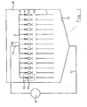
- Fig. 1 shows a water inlet 1, which branches via a manifold 2 to a plurality of water channels 3.
- the objects mentioned are located in a washroom 8 of a cleaning and disinfecting machine, in which cleaning liquid is conveyed by a circulating pump 9 from the sump 10 of the machine via a return channel 11 to the water inlet 1.
- the remaining parts of a commercial cleaning and disinfecting machine such as fresh water inlet, control device, metering device for cleaning and disinfecting agents, etc., are omitted for clarity.
- the flow constriction 4, the pressure sensor 5 and the coupling 6 can be formed as a coherent module 12 and connected to the respective water channel 3.
- the coupling 6 may be self-closing such that it is closed when not connected hollow body 7 and automatically opens by connecting a hollow body.
- each module 12 with an unillustrated shut-off valve.
- the coupling 6 can - as shown - be a so-called. Luer connection.
- the operation of the device is as follows: It is assumed that a hollow body is connected to each module 12 shown.
- liquid is supplied with an inlet pressure P 0 via the manifold 2 the individual water channels 3.
- This inlet pressure P 0 is substantially greater than the pressure with which the individual hollow body 7 are cleaned. It is for example in the order of 1 to 1.5 bar. If the flow path is substantially open, a pressure drop will occur at the respective flow constriction 4, so that a lower pressure P 1 is present at the flow-side outlet of the flow constriction 4, which is for example at 300 mbar.
- This pressure P 1 acts on the respective sensor 5.
- the sensor 5 is equipped with a memory function which stores whether the measured pressure P 1 has exceeded a predetermined value.
- This value can be, for example, 600 mbar and is significant for the fact that the respective hollow body is completely or partially blocked.
- the pressure sensor stores whether this increased value has been exceeded once and then emits a permanent signal, which is maintained even after falling below this increased pressure value again. This can be read after completion of the cleaning process to the individual pressure sensors, whether there the increased pressure value has occurred.
- the associated hollow body can then be sorted out, while the remaining hollow body considered to be properly cleaned.
- Fig. 2 shows a preferred embodiment of a module 12 with a flow restriction or nozzle 4, a pressure sensor 5 with memory function and a clutch 6.
- pressure sensors of the type used here can be implemented in a variety of ways, such as electromechanical sensors with electronic storage, however, the expensive and are sensitive to heat and humidity as well as need a power supply, via sensors with mechanical hold function ( Fig. 3 ) or magnetic holding function ( Fig. 4 ).
- sensors with mechanical hold function Fig. 3
- magnetic holding function Fig. 4
- sensors that uniquely limit the storage function and the function of a safety valve with respect to the maximum pressure that is applied to the hollow body.
- the design of the sensor should be as inexpensive as possible, robust against the effects of temperature and moisture as well as easily adaptable to different input and cleaning pressures P 0 and P 1 .
- the flow constriction 4 is designed as a threaded screw 13 which is screwed into a threaded sleeve 14 which is connected to the water channel 3, and thus projects into the interior of the water channel 13.
- a manually operable rotary handle 15 allows the screwing in and out of the screw 13.
- the pressure P 1 can be adapted quickly and flexibly to the respective requirements arising from the dimensioning of the individual lumens of the hollow bodies 7.
- a very simple embodiment of a pressure sensor 5 consists of a sleeve 16 connected to the water channel and a piston 17 slidingly slidable therein, the end face 18 of which is acted upon by the pressure P 1 in the water channel 3.
- a weight 19 is attached to the piston 17, whose diameter is greater than the diameter of the sleeve 16 and which loads the piston 17 with its own weight.
- the piston 17 and the weight 19 may be integrally formed.
- a disc 20 may be attached, which as Support for the weight 19 is used.
- the weight 19 is fixed by a flexible support 21, which may be, for example, a plastic thread, a metal chain or other, to the sleeve or the water channel 3 and secured against loss.
- the piston 17 and the weight 19 are pressed against the force of gravity along the sleeve 16 by the water channel 3. If the pressure reaches a predetermined limit, the piston 17 is completely pushed out of the sleeve 16 and the sleeve 16 thus acts as an opening of the water channel 13 and thus as a pressure relief valve. The piston 17 with weight 19 is secured by the holder 21 against loss.
- the seal between sleeve 16 and piston 17 is to be chosen so that a movement of the piston 17 is not inhibited, but still can escape only very small amounts of liquid.
- a very compact and simple pressure sensor can be realized, which preferably consists of stainless steel and can be designed for the pressures of interest here in the order of 100 mbar to 1 bar.
- the responsiveness of the sensor is given by the total weight of the weight 19 and the piston 17 and the end face 18.
- Fig. 3 shows an embodiment of a pressure sensor, which also has the sleeve 16, the piston 17 and the weight 19, wherein the weight optionally also by a spring 22 may be loaded.
- the weight is in this case accommodated in a housing 23 which has on its upper side a viewing window 24 made of flexible material.
- the weight has at its radial outer periphery a groove 25.
- In the housing at least one radially inwardly biased against the weight spring 26 is arranged, which has a latching nose 27. If the piston 17 and the weight 19 are raised so far that the locking lug 27 engages in the groove 25, this position of piston and weight remains stored, even if the pressure in the water channel 3 drops again.
- the piston 17 and the weight 19 are in their upper limit position, so the corresponding pressure value has been exceeded. Since the viewing window is flexible, the weight can be pushed back by hand, for example, back down towards the water channel 3 in its normal measuring position.
- the memory function is realized by magnets 28 and 29 which are mounted on the one hand on the piston and on the other hand on the housing 23.
Landscapes
- Health & Medical Sciences (AREA)
- Life Sciences & Earth Sciences (AREA)
- Surgery (AREA)
- Animal Behavior & Ethology (AREA)
- Engineering & Computer Science (AREA)
- Veterinary Medicine (AREA)
- Public Health (AREA)
- General Health & Medical Sciences (AREA)
- Heart & Thoracic Surgery (AREA)
- Biomedical Technology (AREA)
- Molecular Biology (AREA)
- Medical Informatics (AREA)
- Physics & Mathematics (AREA)
- Nuclear Medicine, Radiotherapy & Molecular Imaging (AREA)
- Pathology (AREA)
- Mechanical Engineering (AREA)
- Biophysics (AREA)
- Optics & Photonics (AREA)
- Radiology & Medical Imaging (AREA)
- Epidemiology (AREA)
- Chemical & Material Sciences (AREA)
- General Physics & Mathematics (AREA)
- Chemical Kinetics & Catalysis (AREA)
- General Chemical & Material Sciences (AREA)
- Oral & Maxillofacial Surgery (AREA)
- Infusion, Injection, And Reservoir Apparatuses (AREA)
- External Artificial Organs (AREA)
- Apparatus For Disinfection Or Sterilisation (AREA)
- Measuring Volume Flow (AREA)
- Measuring Fluid Pressure (AREA)
- Endoscopes (AREA)
Claims (9)
- Dispositif de nettoyage et/ou de désinfection de corps creux (7), en particulier, de tubes médicaux et de cathéters, comportant au moins un couplage (6) raccordé à au moins un canal d'eau (3) pour relier le canal d'eau (3) au corps creux (7), dans lequel on prévoit un rétrécissement d'écoulement (4) raccordé, dans le sens de l'écoulement, au canal d'eau (3) avant le couplage (6), et un capteur de pression (5) pour saisir et enregistrer la pression observée dans le corps creux (7), et dans lequel le capteur de pression (5) présente une gaine (16) raccordée au canal d'eau (3) et un piston (17) pouvant être poussé dans la gaine (16).
- Dispositif selon la revendication 1, caractérisé en ce que le capteur de pression (5) est conçu de telle sorte qu'il enregistre, de façon durablement lisible, si la pression saisie a dépassé une valeur prédéterminée.
- Dispositif selon la revendication 2, caractérisé en ce
que le piston (17) est poussé par son propre poids et éventuellement par un poids supplémentaire (19) dans le sens du canal d'eau (3) et sort complètement de la gaine (16) par la pression prédéterminée. - Dispositif selon la revendication 3, caractérisé en ce
que le piston est fixé avec un support flexible (21) au canal d'eau (3) ou à la gaine (16). - Dispositif selon la revendication 4, caractérisé en ce
que le piston (16) est poussé par un ressort (22) dans le sens du canal d'eau (3). - Dispositif selon l'une des revendications 2, 4 ou 5, caractérisé en ce
qu'une encoche d'arrêt (25) est aménagée sur le piston (17, 19), et sur un boîtier (23) se trouve un ressort (26) qui est encliqueté lorsqu'une position limite prédéterminée est atteinte dans l'encoche d'arrêt (25). - Dispositif selon l'une des revendications 2, 4 ou 5, caractérisé en ce
que sur le piston on prévoit au moins un aimant (27), et sur le boîtier (23) dans lequel le piston (17) peut être engagé de façon déplaçable on prévoit un contre-aimant (28). - Dispositif selon l'une des revendications 1 à 7, caractérisé en ce
que le rétrécissement d'écoulement (4) est réglable. - Dispositif selon la revendication 8, caractérisé en ce
que le rétrécissement d'écoulement (4) est une vis (13) pouvant être vissée dans le canal d'eau (3).
Priority Applications (1)
| Application Number | Priority Date | Filing Date | Title |
|---|---|---|---|
| SI200431605T SI1477238T1 (sl) | 2003-05-16 | 2004-03-27 | Naprava za čiščenje in/ali dezinficiranje podolgovatih votlih teles, še zlasti medicinskih gibkih cevi in katetrov |
Applications Claiming Priority (2)
| Application Number | Priority Date | Filing Date | Title |
|---|---|---|---|
| DE10321991 | 2003-05-16 | ||
| DE10321991A DE10321991B3 (de) | 2003-05-16 | 2003-05-16 | Vorrichtung zum Reinigen und/oder Desinfizieren von langgestreckten Hohlkörpern, insbesondere von medizinischen Schläuchen und Kathetern |
Publications (3)
| Publication Number | Publication Date |
|---|---|
| EP1477238A2 EP1477238A2 (fr) | 2004-11-17 |
| EP1477238A3 EP1477238A3 (fr) | 2005-11-30 |
| EP1477238B1 true EP1477238B1 (fr) | 2010-11-17 |
Family
ID=32115635
Family Applications (1)
| Application Number | Title | Priority Date | Filing Date |
|---|---|---|---|
| EP04007482A Expired - Lifetime EP1477238B1 (fr) | 2003-05-16 | 2004-03-27 | Appareil pour nettoyer et/ou désinfecter des corps creux allongés, en particulier tubes médicaux et catheters |
Country Status (5)
| Country | Link |
|---|---|
| EP (1) | EP1477238B1 (fr) |
| AT (1) | ATE488308T1 (fr) |
| DE (2) | DE10321991B3 (fr) |
| DK (1) | DK1477238T3 (fr) |
| SI (1) | SI1477238T1 (fr) |
Cited By (1)
| Publication number | Priority date | Publication date | Assignee | Title |
|---|---|---|---|---|
| DE102013226637A1 (de) | 2013-12-19 | 2015-06-25 | Meiko Maschinenbau Gmbh & Co. Kg | Reinigungsvorrichtung und Verfahren zur Reinigung von Reinigungsgut |
Families Citing this family (15)
| Publication number | Priority date | Publication date | Assignee | Title |
|---|---|---|---|---|
| DE102004040734B3 (de) * | 2004-08-20 | 2005-09-15 | Bht Hygienetechnik Gmbh | Vorrichtung zum Reinigen und/oder Desinfizieren von langgestreckten Hohlkörpern, insbesondere von medizinischen Schläuchen und Kathetern |
| US7901349B2 (en) * | 2005-11-02 | 2011-03-08 | Minntech Corporation | Endoscope reprocessor connectivity apparatus and method |
| DE102006031918A1 (de) * | 2006-07-10 | 2008-01-17 | Christian Kluge | Transportable Vorrichtung zur Beseitigung von Mikroorganismen |
| DE102009036564A1 (de) * | 2009-08-10 | 2011-02-17 | Olympus Winter & Ibe Gmbh | Verbindungsvorrichtung zur Verwendung in einem Reinigungsraum in einer Reinigungsvorrichtung zur Reinigung von chirurgischen Instrumenten |
| US8673212B2 (en) * | 2010-05-28 | 2014-03-18 | Steris Corporation | Apparatus to decontaminate equipment containing internal channels |
| DE102011082776A1 (de) * | 2011-09-15 | 2013-03-21 | Olympus Winter & Ibe Gmbh | Verfahren und Vorrichtung zum Spülen von Endoskopkanälen |
| DE102012020934B4 (de) | 2012-10-25 | 2014-08-21 | SciCan GmbH | Verfahren zum Reinigen und Desinfizieren von Endoskopen |
| DE102013204038B4 (de) | 2013-03-08 | 2016-10-27 | Melag Medizintechnik Ohg | Trägersystem zur Aufnahme von medizinischen oder zahnmedizinischen Instrumenten und Verfahren zur Bestimmung einer Flüssigkeitsdurchlässigkeit eines Filters eines solchen Trägersystems |
| CN105499223A (zh) * | 2015-12-30 | 2016-04-20 | 天津市鑫思汇智科技发展有限公司 | 一种医疗器械循环灌流清洗装置 |
| CN110976410A (zh) * | 2019-11-19 | 2020-04-10 | 老肯医疗科技股份有限公司 | 一种用于清洗管腔器械的清洗管路系统及其使用方法 |
| CN111804678A (zh) * | 2020-07-17 | 2020-10-23 | 提技贸易(上海)有限公司 | 一种中央排管自动清扫系统及控制方法 |
| EP4344609B1 (fr) | 2022-09-30 | 2025-10-01 | Hammann GmbH | Procédé et appareil de nettoyage d'instruments médicaux au moyen d'impulsions de gaz sous pression modulantes |
| CN115722500A (zh) * | 2022-11-30 | 2023-03-03 | 山东黄河三角洲纺织科技研究院有限公司 | 一种编织型人造血管的清洗装置及其清洗方法 |
| CN115655589B (zh) * | 2022-12-05 | 2023-03-14 | 常州瑞迈医疗科技有限公司 | 一种管状医疗器械用密封性测试装置 |
| CN117816664B (zh) * | 2023-12-28 | 2025-11-07 | 中铁十四局集团有限公司 | 一种泥水盾构机冲刷管路清堵装置及方法 |
Family Cites Families (5)
| Publication number | Priority date | Publication date | Assignee | Title |
|---|---|---|---|---|
| JPS61257624A (ja) * | 1985-01-18 | 1986-11-15 | オリンパス光学工業株式会社 | 内視鏡洗浄機の異常表示装置 |
| NL9401788A (nl) | 1994-10-27 | 1996-06-03 | Fujinon Medical Holland B V | Werkwijze en inrichting voor het reinigen en desinfecteren van endoscopen. |
| DE4440363C2 (de) * | 1994-11-11 | 1997-10-02 | Netzsch Newamatic Gmbh | Verfahren zum Prüfen und Reinigen von Instrumenten für die minimal invasive Chirurgie oder minimal invasive Untersuchung von Körperhöhlen |
| DE29620011U1 (de) * | 1996-11-18 | 1997-01-09 | Biermaier, Hans, 86316 Friedberg | Vorrichtung zur Innenreinigung hohler medizinischer Gegenstände, insbesondere von Kathetern oder Schläuchen |
| DE10208035B4 (de) | 2002-02-26 | 2005-10-06 | Bht Hygiene Technik Gmbh | Vorrichtung zum Überprüfen der Durchgängigkeit von Endoskopkanälen |
-
2003
- 2003-05-16 DE DE10321991A patent/DE10321991B3/de not_active Expired - Fee Related
-
2004
- 2004-03-27 DK DK04007482.5T patent/DK1477238T3/da active
- 2004-03-27 EP EP04007482A patent/EP1477238B1/fr not_active Expired - Lifetime
- 2004-03-27 SI SI200431605T patent/SI1477238T1/sl unknown
- 2004-03-27 AT AT04007482T patent/ATE488308T1/de active
- 2004-03-27 DE DE502004011888T patent/DE502004011888D1/de not_active Expired - Lifetime
Cited By (3)
| Publication number | Priority date | Publication date | Assignee | Title |
|---|---|---|---|---|
| DE102013226637A1 (de) | 2013-12-19 | 2015-06-25 | Meiko Maschinenbau Gmbh & Co. Kg | Reinigungsvorrichtung und Verfahren zur Reinigung von Reinigungsgut |
| WO2015091750A1 (fr) | 2013-12-19 | 2015-06-25 | Meiko Maschinenbau Gmbh & Co. Kg | Dispositif de nettoyage et procédé pour le nettoyage d'objets à nettoyer |
| US10561294B2 (en) | 2013-12-19 | 2020-02-18 | Meiko Maschinenbau Gmbh & Co., Kg | Cleaning appliance and method for cleaning articles to be cleaned |
Also Published As
| Publication number | Publication date |
|---|---|
| SI1477238T1 (sl) | 2011-06-30 |
| DK1477238T3 (da) | 2011-03-07 |
| DE502004011888D1 (de) | 2010-12-30 |
| ATE488308T1 (de) | 2010-12-15 |
| EP1477238A3 (fr) | 2005-11-30 |
| EP1477238A2 (fr) | 2004-11-17 |
| DE10321991B3 (de) | 2004-05-19 |
Similar Documents
| Publication | Publication Date | Title |
|---|---|---|
| EP1477238B1 (fr) | Appareil pour nettoyer et/ou désinfecter des corps creux allongés, en particulier tubes médicaux et catheters | |
| EP1749549B1 (fr) | Système de drainage de fluide cephalo-rachidien | |
| EP2020198B1 (fr) | Procédé et dispositif destinés à transporter des produits alimentaires | |
| EP2981306B1 (fr) | Dispositif doté d'un conduit d'écoulement | |
| EP2617286B1 (fr) | Pulvérisateur agricole à cultures | |
| EP1593345B1 (fr) | Appareil de contrôle automatique du débit d'un fluide, en particulier d'urine | |
| DE3706338A1 (de) | Membranpumpvorrichtung | |
| DE2754809A1 (de) | Vorrichtung zur periodischen spuelung von koerperhoehlen, insbesondere der bauchhoehle | |
| EP1950281B1 (fr) | Dispositif de mesure destiné à la détermination de l'activité d'un processus de fermentation | |
| DE3440848C2 (fr) | ||
| EP0143294B1 (fr) | Dispositif pour le dosage d'un composé à un solvant ou diluant | |
| DE10208035B4 (de) | Vorrichtung zum Überprüfen der Durchgängigkeit von Endoskopkanälen | |
| DE3041593A1 (de) | Automatische sprueheinrichtung | |
| DE102005058012B4 (de) | Verfahren zum Freiblasen eines benetzten Hydrophobfilters und Vorrichtung zur Durchführung des Verfahrens | |
| EP1627693B1 (fr) | Dispositif de nettoyage et/ou de désinfection des corps creux, en particulier des tubes médicaux et des cathéters | |
| DE69927652T2 (de) | Dosiervorrichtung für nicht-gasförmiges fliessfähiges Material | |
| DE102014103071A1 (de) | Sterilisationsapparat | |
| DE102018106790A1 (de) | Container sowie Verfahren zu dessen Betrieb | |
| DE10352198B4 (de) | Verfahren zur Analyse von Kanälen, insbesondere Endoskopkanälen, und Vorrichtung zur Durchführung des Verfahrens | |
| WO2014086554A2 (fr) | Procédé et dispositif permettant d'indiquer la position d'accessoires de robinetterie à commande hydraulique | |
| EP3449804B1 (fr) | Procédé et dispositif de vérification simultanée de connection d'un adaptateur et de l'ouverture des canaux de l'endoscope | |
| DE102020202951A1 (de) | Dosiervorrichtung und Verfahren zum Betreiben einer Dosiervorrichtung | |
| EP3221195B1 (fr) | Système d'air comprimé à capteur hygroscopique | |
| DE102017123829A1 (de) | Durchflussanzeigevorrichtung zum Anzeigen eines Durchflusses von Fluid durch in einem Reinigungsgerät angeordnetes Spülgut und Reinigungsgerät | |
| DE3306922A1 (de) | Steuerungseinrichtung zum abfuellen von fluessigkeiten |
Legal Events
| Date | Code | Title | Description |
|---|---|---|---|
| PUAI | Public reference made under article 153(3) epc to a published international application that has entered the european phase |
Free format text: ORIGINAL CODE: 0009012 |
|
| AK | Designated contracting states |
Kind code of ref document: A2 Designated state(s): AT BE BG CH CY CZ DE DK EE ES FI FR GB GR HU IE IT LI LU MC NL PL PT RO SE SI SK TR |
|
| AX | Request for extension of the european patent |
Extension state: AL LT LV MK |
|
| PUAL | Search report despatched |
Free format text: ORIGINAL CODE: 0009013 |
|
| AK | Designated contracting states |
Kind code of ref document: A3 Designated state(s): AT BE BG CH CY CZ DE DK EE ES FI FR GB GR HU IE IT LI LU MC NL PL PT RO SE SI SK TR |
|
| AX | Request for extension of the european patent |
Extension state: AL LT LV MK |
|
| 17P | Request for examination filed |
Effective date: 20060329 |
|
| AKX | Designation fees paid |
Designated state(s): AT BE BG CH CY CZ DE DK EE ES FI FR GB GR HU IE IT LI LU MC NL PL PT RO SE SI SK TR |
|
| 17Q | First examination report despatched |
Effective date: 20070111 |
|
| GRAP | Despatch of communication of intention to grant a patent |
Free format text: ORIGINAL CODE: EPIDOSNIGR1 |
|
| GRAJ | Information related to disapproval of communication of intention to grant by the applicant or resumption of examination proceedings by the epo deleted |
Free format text: ORIGINAL CODE: EPIDOSDIGR1 |
|
| GRAP | Despatch of communication of intention to grant a patent |
Free format text: ORIGINAL CODE: EPIDOSNIGR1 |
|
| GRAC | Information related to communication of intention to grant a patent modified |
Free format text: ORIGINAL CODE: EPIDOSCIGR1 |
|
| GRAJ | Information related to disapproval of communication of intention to grant by the applicant or resumption of examination proceedings by the epo deleted |
Free format text: ORIGINAL CODE: EPIDOSDIGR1 |
|
| RTI1 | Title (correction) |
Free format text: APPARATUS FOR CLEANING AND/OR DESINFECTING ELONGATED HOLLOW BODIES, IN PARTICULAR MEDICAL TUBES AND CATHETERS |
|
| GRAP | Despatch of communication of intention to grant a patent |
Free format text: ORIGINAL CODE: EPIDOSNIGR1 |
|
| GRAS | Grant fee paid |
Free format text: ORIGINAL CODE: EPIDOSNIGR3 |
|
| GRAA | (expected) grant |
Free format text: ORIGINAL CODE: 0009210 |
|
| AK | Designated contracting states |
Kind code of ref document: B1 Designated state(s): AT BE BG CH CY CZ DE DK EE ES FI FR GB GR HU IE IT LI LU MC NL PL PT RO SE SI SK TR |
|
| REG | Reference to a national code |
Ref country code: GB Ref legal event code: FG4D Free format text: NOT ENGLISH |
|
| REG | Reference to a national code |
Ref country code: CH Ref legal event code: EP |
|
| REG | Reference to a national code |
Ref country code: IE Ref legal event code: FG4D |
|
| REF | Corresponds to: |
Ref document number: 502004011888 Country of ref document: DE Date of ref document: 20101230 Kind code of ref document: P |
|
| REG | Reference to a national code |
Ref country code: DK Ref legal event code: T3 |
|
| REG | Reference to a national code |
Ref country code: NL Ref legal event code: VDEP Effective date: 20101117 |
|
| PG25 | Lapsed in a contracting state [announced via postgrant information from national office to epo] |
Ref country code: PT Free format text: LAPSE BECAUSE OF FAILURE TO SUBMIT A TRANSLATION OF THE DESCRIPTION OR TO PAY THE FEE WITHIN THE PRESCRIBED TIME-LIMIT Effective date: 20110317 Ref country code: NL Free format text: LAPSE BECAUSE OF FAILURE TO SUBMIT A TRANSLATION OF THE DESCRIPTION OR TO PAY THE FEE WITHIN THE PRESCRIBED TIME-LIMIT Effective date: 20101117 Ref country code: CY Free format text: LAPSE BECAUSE OF FAILURE TO SUBMIT A TRANSLATION OF THE DESCRIPTION OR TO PAY THE FEE WITHIN THE PRESCRIBED TIME-LIMIT Effective date: 20101117 Ref country code: SE Free format text: LAPSE BECAUSE OF FAILURE TO SUBMIT A TRANSLATION OF THE DESCRIPTION OR TO PAY THE FEE WITHIN THE PRESCRIBED TIME-LIMIT Effective date: 20101117 Ref country code: BG Free format text: LAPSE BECAUSE OF FAILURE TO SUBMIT A TRANSLATION OF THE DESCRIPTION OR TO PAY THE FEE WITHIN THE PRESCRIBED TIME-LIMIT Effective date: 20110217 Ref country code: FI Free format text: LAPSE BECAUSE OF FAILURE TO SUBMIT A TRANSLATION OF THE DESCRIPTION OR TO PAY THE FEE WITHIN THE PRESCRIBED TIME-LIMIT Effective date: 20101117 |
|
| REG | Reference to a national code |
Ref country code: IE Ref legal event code: FD4D |
|
| PG25 | Lapsed in a contracting state [announced via postgrant information from national office to epo] |
Ref country code: GR Free format text: LAPSE BECAUSE OF FAILURE TO SUBMIT A TRANSLATION OF THE DESCRIPTION OR TO PAY THE FEE WITHIN THE PRESCRIBED TIME-LIMIT Effective date: 20110218 |
|
| PG25 | Lapsed in a contracting state [announced via postgrant information from national office to epo] |
Ref country code: IE Free format text: LAPSE BECAUSE OF FAILURE TO SUBMIT A TRANSLATION OF THE DESCRIPTION OR TO PAY THE FEE WITHIN THE PRESCRIBED TIME-LIMIT Effective date: 20101117 Ref country code: ES Free format text: LAPSE BECAUSE OF FAILURE TO SUBMIT A TRANSLATION OF THE DESCRIPTION OR TO PAY THE FEE WITHIN THE PRESCRIBED TIME-LIMIT Effective date: 20110228 Ref country code: CZ Free format text: LAPSE BECAUSE OF FAILURE TO SUBMIT A TRANSLATION OF THE DESCRIPTION OR TO PAY THE FEE WITHIN THE PRESCRIBED TIME-LIMIT Effective date: 20101117 Ref country code: EE Free format text: LAPSE BECAUSE OF FAILURE TO SUBMIT A TRANSLATION OF THE DESCRIPTION OR TO PAY THE FEE WITHIN THE PRESCRIBED TIME-LIMIT Effective date: 20101117 |
|
| PG25 | Lapsed in a contracting state [announced via postgrant information from national office to epo] |
Ref country code: PL Free format text: LAPSE BECAUSE OF FAILURE TO SUBMIT A TRANSLATION OF THE DESCRIPTION OR TO PAY THE FEE WITHIN THE PRESCRIBED TIME-LIMIT Effective date: 20101117 Ref country code: RO Free format text: LAPSE BECAUSE OF FAILURE TO SUBMIT A TRANSLATION OF THE DESCRIPTION OR TO PAY THE FEE WITHIN THE PRESCRIBED TIME-LIMIT Effective date: 20101117 Ref country code: SK Free format text: LAPSE BECAUSE OF FAILURE TO SUBMIT A TRANSLATION OF THE DESCRIPTION OR TO PAY THE FEE WITHIN THE PRESCRIBED TIME-LIMIT Effective date: 20101117 |
|
| PLBE | No opposition filed within time limit |
Free format text: ORIGINAL CODE: 0009261 |
|
| STAA | Information on the status of an ep patent application or granted ep patent |
Free format text: STATUS: NO OPPOSITION FILED WITHIN TIME LIMIT |
|
| BERE | Be: lapsed |
Owner name: BHT HYGIENETECHNIK G.M.B.H. Effective date: 20110331 |
|
| 26N | No opposition filed |
Effective date: 20110818 |
|
| PG25 | Lapsed in a contracting state [announced via postgrant information from national office to epo] |
Ref country code: MC Free format text: LAPSE BECAUSE OF NON-PAYMENT OF DUE FEES Effective date: 20110331 |
|
| REG | Reference to a national code |
Ref country code: DE Ref legal event code: R097 Ref document number: 502004011888 Country of ref document: DE Effective date: 20110818 |
|
| PG25 | Lapsed in a contracting state [announced via postgrant information from national office to epo] |
Ref country code: IT Free format text: LAPSE BECAUSE OF FAILURE TO SUBMIT A TRANSLATION OF THE DESCRIPTION OR TO PAY THE FEE WITHIN THE PRESCRIBED TIME-LIMIT Effective date: 20101117 Ref country code: BE Free format text: LAPSE BECAUSE OF NON-PAYMENT OF DUE FEES Effective date: 20110331 |
|
| PGFP | Annual fee paid to national office [announced via postgrant information from national office to epo] |
Ref country code: CH Payment date: 20130319 Year of fee payment: 10 Ref country code: DK Payment date: 20130320 Year of fee payment: 10 Ref country code: GB Payment date: 20130318 Year of fee payment: 10 Ref country code: FR Payment date: 20130329 Year of fee payment: 10 |
|
| PG25 | Lapsed in a contracting state [announced via postgrant information from national office to epo] |
Ref country code: LU Free format text: LAPSE BECAUSE OF NON-PAYMENT OF DUE FEES Effective date: 20110327 |
|
| PGFP | Annual fee paid to national office [announced via postgrant information from national office to epo] |
Ref country code: SI Payment date: 20130320 Year of fee payment: 10 |
|
| PGFP | Annual fee paid to national office [announced via postgrant information from national office to epo] |
Ref country code: AT Payment date: 20130318 Year of fee payment: 10 |
|
| PG25 | Lapsed in a contracting state [announced via postgrant information from national office to epo] |
Ref country code: TR Free format text: LAPSE BECAUSE OF FAILURE TO SUBMIT A TRANSLATION OF THE DESCRIPTION OR TO PAY THE FEE WITHIN THE PRESCRIBED TIME-LIMIT Effective date: 20101117 |
|
| PG25 | Lapsed in a contracting state [announced via postgrant information from national office to epo] |
Ref country code: HU Free format text: LAPSE BECAUSE OF FAILURE TO SUBMIT A TRANSLATION OF THE DESCRIPTION OR TO PAY THE FEE WITHIN THE PRESCRIBED TIME-LIMIT Effective date: 20101117 |
|
| REG | Reference to a national code |
Ref country code: DK Ref legal event code: EBP Effective date: 20140331 |
|
| REG | Reference to a national code |
Ref country code: CH Ref legal event code: PL |
|
| REG | Reference to a national code |
Ref country code: AT Ref legal event code: MM01 Ref document number: 488308 Country of ref document: AT Kind code of ref document: T Effective date: 20140327 |
|
| GBPC | Gb: european patent ceased through non-payment of renewal fee |
Effective date: 20140327 |
|
| REG | Reference to a national code |
Ref country code: FR Ref legal event code: ST Effective date: 20141128 |
|
| REG | Reference to a national code |
Ref country code: SI Ref legal event code: KO00 Effective date: 20141104 |
|
| PG25 | Lapsed in a contracting state [announced via postgrant information from national office to epo] |
Ref country code: FR Free format text: LAPSE BECAUSE OF NON-PAYMENT OF DUE FEES Effective date: 20140331 Ref country code: CH Free format text: LAPSE BECAUSE OF NON-PAYMENT OF DUE FEES Effective date: 20140331 Ref country code: LI Free format text: LAPSE BECAUSE OF NON-PAYMENT OF DUE FEES Effective date: 20140331 Ref country code: GB Free format text: LAPSE BECAUSE OF NON-PAYMENT OF DUE FEES Effective date: 20140327 |
|
| PG25 | Lapsed in a contracting state [announced via postgrant information from national office to epo] |
Ref country code: SI Free format text: LAPSE BECAUSE OF NON-PAYMENT OF DUE FEES Effective date: 20140328 Ref country code: AT Free format text: LAPSE BECAUSE OF NON-PAYMENT OF DUE FEES Effective date: 20140327 |
|
| PG25 | Lapsed in a contracting state [announced via postgrant information from national office to epo] |
Ref country code: DK Free format text: LAPSE BECAUSE OF NON-PAYMENT OF DUE FEES Effective date: 20140331 |
|
| PGFP | Annual fee paid to national office [announced via postgrant information from national office to epo] |
Ref country code: DE Payment date: 20230329 Year of fee payment: 20 |
|
| P01 | Opt-out of the competence of the unified patent court (upc) registered |
Effective date: 20230513 |
|
| REG | Reference to a national code |
Ref country code: DE Ref legal event code: R071 Ref document number: 502004011888 Country of ref document: DE |