EP1477253B1 - System zum Abgiessen vom Metallschmelze - Google Patents
System zum Abgiessen vom Metallschmelze Download PDFInfo
- Publication number
- EP1477253B1 EP1477253B1 EP03101083A EP03101083A EP1477253B1 EP 1477253 B1 EP1477253 B1 EP 1477253B1 EP 03101083 A EP03101083 A EP 03101083A EP 03101083 A EP03101083 A EP 03101083A EP 1477253 B1 EP1477253 B1 EP 1477253B1
- Authority
- EP
- European Patent Office
- Prior art keywords
- container
- molten material
- wall
- moving
- pouring
- Prior art date
- Legal status (The legal status is an assumption and is not a legal conclusion. Google has not performed a legal analysis and makes no representation as to the accuracy of the status listed.)
- Expired - Lifetime
Links
- 229910052751 metal Inorganic materials 0.000 title claims abstract description 23
- 239000002184 metal Substances 0.000 title claims abstract description 23
- 238000010079 rubber tapping Methods 0.000 title claims abstract description 14
- 150000002739 metals Chemical class 0.000 title claims description 5
- 239000012768 molten material Substances 0.000 claims abstract description 65
- 238000002844 melting Methods 0.000 claims description 9
- 230000008018 melting Effects 0.000 claims description 9
- 239000000463 material Substances 0.000 claims description 7
- 229910045601 alloy Inorganic materials 0.000 claims description 5
- 239000000956 alloy Substances 0.000 claims description 5
- 239000007788 liquid Substances 0.000 abstract description 20
- 230000005484 gravity Effects 0.000 abstract description 3
- 230000008901 benefit Effects 0.000 description 10
- 230000007246 mechanism Effects 0.000 description 4
- 230000004075 alteration Effects 0.000 description 3
- 238000011109 contamination Methods 0.000 description 3
- 238000004512 die casting Methods 0.000 description 2
- 238000000034 method Methods 0.000 description 2
- 230000005855 radiation Effects 0.000 description 2
- ATJFFYVFTNAWJD-UHFFFAOYSA-N Tin Chemical compound [Sn] ATJFFYVFTNAWJD-UHFFFAOYSA-N 0.000 description 1
- 239000004411 aluminium Substances 0.000 description 1
- 229910052782 aluminium Inorganic materials 0.000 description 1
- XAGFODPZIPBFFR-UHFFFAOYSA-N aluminium Chemical compound [Al] XAGFODPZIPBFFR-UHFFFAOYSA-N 0.000 description 1
- 230000008859 change Effects 0.000 description 1
- 238000004891 communication Methods 0.000 description 1
- 238000010276 construction Methods 0.000 description 1
- 230000007423 decrease Effects 0.000 description 1
- 238000005516 engineering process Methods 0.000 description 1
- 230000006872 improvement Effects 0.000 description 1
- 239000006060 molten glass Substances 0.000 description 1
- 230000003647 oxidation Effects 0.000 description 1
- 238000007254 oxidation reaction Methods 0.000 description 1
- 230000008569 process Effects 0.000 description 1
- 239000002699 waste material Substances 0.000 description 1
Images


Classifications
-
- B—PERFORMING OPERATIONS; TRANSPORTING
- B22—CASTING; POWDER METALLURGY
- B22D—CASTING OF METALS; CASTING OF OTHER SUBSTANCES BY THE SAME PROCESSES OR DEVICES
- B22D17/00—Pressure die casting or injection die casting, i.e. casting in which the metal is forced into a mould under high pressure
- B22D17/20—Accessories: Details
- B22D17/30—Accessories for supplying molten metal, e.g. in rations
-
- B—PERFORMING OPERATIONS; TRANSPORTING
- B22—CASTING; POWDER METALLURGY
- B22D—CASTING OF METALS; CASTING OF OTHER SUBSTANCES BY THE SAME PROCESSES OR DEVICES
- B22D39/00—Equipment for supplying molten metal in rations
- B22D39/02—Equipment for supplying molten metal in rations having means for controlling the amount of molten metal by volume
-
- B—PERFORMING OPERATIONS; TRANSPORTING
- B22—CASTING; POWDER METALLURGY
- B22D—CASTING OF METALS; CASTING OF OTHER SUBSTANCES BY THE SAME PROCESSES OR DEVICES
- B22D41/00—Casting melt-holding vessels, e.g. ladles, tundishes, cups or the like
Definitions
- the invention relates to a system for tapping and pouring molten material having a melting point above 0 Celsius degrees, comprising a first container and a second container capable of being introduced into the first container.
- One way to perform this operation is to make use of a ladle capable of being plunged into a bath of molten material, and further capable of taking out a particular amount of said molten material, transporting it for instance on top of a mould to be filled and pouring the molten material into the mould, either by tilting the ladle and by letting the molten material going through a spout or by opening a valve and letting the molten material to drain away through said valve.
- a system using the above principle is the "Hodler system", as illustrated in Fig. 219 of page 126 of "Technologie de la Fonderie en Moules Metalliques, Fonderie sous pression", Edition techniques des industries de la fonderie, Paris 1968.
- a container is plunged into a crucible which contains molten metal. Said container is then filled up with molten metal. The container is then removed from the crucible by mechanical means and carried to a place above a mould or a channel leading to a mould. A valve located on the bottom of the mobile container is opened to let the liquid drain away towards the mould.
- the system according to the invention is such that, in operation, the first container is filled with molten material.
- the second container is arranged inside the first container and executes in operation a movement inside the first container, i.e. the second container remains inside the first container, thus not causing dripping of molten material outside the system and causing less alteration of the molten material, for instance less oxidation and contamination of the molten metal.
- This is a first advantage over the systems known in the prior art in which molten material often drips from the mobile container, which results in needless loss of material and safety problems.
- This is the case of the "Hodler system” which also presents the propensity to cause important alteration to the molten material, due to the relatively long transportation time mainly outside the crucible.
- the system according to the invention significantly improves this situation since the transportation of the molten material before pouring is simplified in a significant way.
- a second advantage of the system according to the invention is that pouring can easily be controlled and stopped by reversing or stopping the movement of the second container without loss or risk of alteration of the molten material since the molten material which is not poured remains inside the second container and thus inside the first container.
- a third advantage is that the system is very compact, since the second container does not leave the first container. It means, firstly, that the occupied area on the floor is smaller and, secondly, that the system is much cleaner since the elements of said system are concentrated in a relatively smaller volume, thus requiring less protecting means to constrain to a particular area the high temperatures, the heat radiation, the polluted atmosphere, the molten material ejection and the like.
- a fourth advantage is that the heat remains subtantially inside the system up until the metal is actually poured, because no molten metal is transported outside the first container until it is poured.
- the mobile container is transported away from the crucible in such a way as to lead to a larger loss of energy and to subject a larger area to safety hazard.
- a fifth advantage of the system according to the invention is that only relatively small and simple movements are involved in the tapping and pouring operations since the second container remains inside the first container. No complex movement is required since the second container moves with respect to the common element and thus the movement is at least to some extent guided, i.e. for instance only a certain type or certain types of movement, such as a translation or a rotation of the second container with respect to the first container, are possible. Moreover, the system may be totally automatized without complex mechanisms thanks to its simplicity.
- the characteritics of the invention provide an at least partial solution to the mentioned problems of the prior art tapping and pouring systems, said problems being very specific to molten materials having a melting point above 0 Celsius degrees. Indeed, the circumstances in which these systems are used are very particular, due to the extreme temperatures, the intense radiation, the polluted surrounding atmosphere, the molten metal ejections and so forth. Many normal material and devices cannot be used in these circumstances and any new improvement must be designed keeping in mind the specific context involved.
- system according to the invention is simpler, more compact, cleaner, less expensive and easier to install and maintain but yet provides for greater accuracy in pouring amounts of molten material, surprising though it may seem.
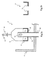
- Fig. 1a shows a schematic cross-section representation of an example of the system (2) according to the invention, in operation, while the second container (6) is entirely plunged into the first container bath (8).
- the first container (4) or crucible contains indeed a bath (8) of molten material, for instance a molten metal, which communicates through a first channel (20) for instance with another crucible, although it will be clear for the person skilled in the art that such a communication channel (20) is neither essential nor compulsory to the invention.
- a second channel (18) or hollow inner tube is located substantially inside the first container (4) and extends from above the level L B of the first container bath (8) to below the bottom of the first container (4), thus forming a inner wall (26), common to both the first container (4) and the second container (6).
- Said second channel (18) may have a cylindrical shape and may be surrounded by the liquid bath (8).
- a second container (6) is arranged inside, i.e. fit in, the first container (4) in such a way as, first, to be substantially in contact through a joint (22) or not with the wall (26), secondly, to extend around the second channel (18), for instance to form a cylindrical shape around said channel (18) if said channel (18) has a cylindrical shape, and, thirdly, to be capable of moving vertically only.
- some means for lifting the second container (6) are provided in order to produce the vertical movement of the second container (6), i.e. in order to lift it and to lift it down.
- a jack (16) is represented and controls the second container's (6) movement via some rods (14). Nonetheless, it will be clear for the person skilled in the art that some other means may be used without departing from the invention.
- Fig. 1b shows the system (2) of Fig. 1a while the second container liquid level is slightly above the overflow limit, i.e. the level L A .
- Fig. 1b is a schematic representation of the system (2) of Fig. 1a at an instant just before some liquid of the second container liquid bath (10) goes through the aperture (12).
- Fig. 1a shows the second container (6) at the filling position
- Fig. 1b shows said second container (6) at the pouring position, just before the pouring step actually occurs.
- Fig. 1c shows the system (2) of Fig. 1a while the second container liquid level is above the level L A and while the exceeding molten material (24) is flowing over the brim of the aperture (12). It will be clear from the person skilled in the art that there may be no aperture (10) and that the exceeding molten material (24) may flow through an overflow outlet system, over the brim of the top of the second channel (18) or via any means of letting the liquid flow without departing from the invention.
- Fig. 1d shows a top view of the system (2) of Fig. 1c. Both containers (4, 6) are shown and the exceeding molten material (24) is also shown when falling with gravity through the second channel (18).
- the dashed line A represents the plan according to which the cross-section of Fig. 1c is made.
- the means (16) for lifting the second container (6) is not shown in Fig. 1d in order to keep said figure as clear as possible.
- the successive steps shown in the Fig. 1a, 1b and 1c illustrate an example of a way of operating the system (2) according to the invention in order to tap a particular amount or volume of molten material from the bath (8), lift it in a second container (6) and pour it through an aperture (12) in a channel leading for instance to a mould.
- the volume it is capable to hold is reduced and depends on said particular level.
- the overflowing molten material (24) that will may be poured into the mould depends on the level to which the second container (6) is lifted.
- the system (2) may be used for tapping and pouring different volumes or quantities without having to alter the components of said system (2).
- the molten material that is poured into e.g. a mould may consequently be controlled by the level to which the second container (6) is lifted.
- means for stopping the means (16) for lifting the second container (6) may be provided.
- a jack (16) with a carriage stop (32) may be used.
- Said means for stopping the lifting movement for instance an adjustable carriage stop (32), may be such that it is possible to adapt said means in order to change the volume of liquid to be poured.
- an adjustable carriage stop 32
- this is an important advantage over the tapping and pouring systems as known in the art.
- One notable advantage of the embodiment of the system (2) shown in Fig. 1a, 1b and 1c is that, during the operation, the molten material stays, at least for some time heated by the molten material surrounding the inner tube (18), thus creating less heat and less contamination.
- Fig. 2a shows a schematic cross-section representation of an example of the system (2) according to the invention, while not in operation, i.e. without any liquid in the containers (4, 6).
- a first maximum volume V 1 is shown, this is the volume that can be contained by the second container (6) while fit into the first container (4).
- the volume V 1 is delimited by the wall (26), the walls of the first container (6) and the dashed line that would be the level of liquid in the second container (6) if it was full to the brim, for instance at the filling position.
- FIG. 2b shows the second container (6) of the system (2) of Fig. 2a, while said second container (6) is completely separated from the first container (4), but, nonetheless, in the same orientation and configuration as the orientation and configuration shown in Fig. 2a.
- the second maximum volume V 2 is represented and is the volume that can be contained by the second container (6) while completely separated from the first container (4).
- the second maximum volume V 2 is different from the first maximum volume V 1 .
- the volume V 2 is smaller than volume V 1 and the volume V 1 is larger than 0.
- the difference of volume highlighted here is a characteristic of a class of systems (2) according to the invention, the class of systems (2) in which, in operation, the second container (6) only translates with respect to the common element, i.e. the wall (26). In operation, during the process of lifting the second container (6) out of the bath (8), from a certain moment on, the volume that can be contained by the second container (6) is not anymore equal to V 1 and decreases towards V 2 .
- the third volume V 3 is defined as the maximum volume of molten material which can be contained into the second container (6) while the means (16) for moving said container bumps into the adjustable carriage stop (32) when said carriage stop (32) is at its highest position.
- the fourth volume V 4 is shown on Fig. 1c and 4 and is defined as the maximum volume of molten material which can be contained into the second container (6) while the means (16) for moving said container bumps into the adjustable carriage stop (32), said carriage stop (32) being in a particular intermediate position.
- the difference between the first maximum volume V 1 and the third volume V 3 and the difference between said first maximum volume V 1 and the fourth volume V 4 represent, for a particular system according to the invention, the maximum volume of exceeding molten material that may exit the containers, respectively while the carriage stop (32) is at its highest position and while the carriage stop (32) is at a particular intermediate position.
- the accurate exceeding volumes that may exit the containers as explained, one must subtract from these differences of volume the possible small quantity of molten material which may leak through the joint (22), said quantity being controlled and independent of the level of molten material L B of the first container (4).
- the second container (6) shown in Fig. 2b is disassembled from the system (2) according to the invention. Indeed, as explained above, in operation, the system (2) according to the invention is such that the second container (6) is arranged inside the first container (4) and remains in it throughout the entire operation of tapping and pouring.
- the second maximum volume V 2 is substantially equal to zero.
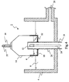
- the exceeding molten material (24) flows through an exit in a third channel (28), which starts in an inner wall common to the first container (4) and to the second container (6), said exit being formed by a brim, an edge or a part of an edge of said wall, the means (16) for moving being then for moving the second container (6) up and down said wall.
- a schematic cross-section representation of said system (2), in operation, is shown in Fig. 3a.
- the second container liquid level is above the overflow limit and the exceeding molten material (24) is flowing through the third channel (28).
- the second container (6) is fit into the first container (4) in such a way as to be substantially in contact via the joint (22) with said first container (4), to be capable of moving vertically in respect to the first container (4) and to be also capable of holding a bath of liquid (10).
- the second container (6) has a shape which may be generated by the rotation of a "L" around an vertical axis, even though it will be clear for the person skilled in the art that the second container's (6) shape may be different without departing from the invention.
- Fig. 3b shows a top view of the system of Fig. 3a.
- the dashed line B represents the plan according to which the cross-section of Fig. 3a is made.
- the means (16) for lifting the second container (6) is not shown in Fig. 1d in order to keep said figure as clear as possible.
- One notable advantage of the embodiment of the system (2) shown in Fig. 3a is that the construction is simple, i.e. there is no need of installing an inner tube (18) in the first container (4).
- the second container (6) executes a rotation with respect to a rotation axis linking both containers.
- the rotation axis is the common element mentionned above.
- the characteristic stating that the common element (26) comprises an exit must be understood by the following meaning: said exit may be formed in the common element (26) or located in the vicinity of said common element (26) with departing from the system (2) according to the invention.
- Fig. 4 shows another embodiment of the system (2) according to the invention while the exit (12) is an aperture in the inner wall (26). This embodiment is very similar to the system (2) shown in Fig. 1a, 1b, 1c and 1d.
- the high-temperature molten material in operation, is a molten metal, such as aluminium, tin, lead or any other metal or alloy of metals. It may also be a molten glass.
- high-temperature molten material it must be understood that the concerned material has a melting point above about 0 Celsius degrees.
- the material is a metal or an alloy of metals having a melting point comprised between 0 Celsius degrees and 1000 Celsius degrees.
- the alloy is, in a particular embodiment, an alloy of metals having a low melting point.
- the molten material is a molten metal and the joint (22) is generally entirely plunged in the bath (8) at any time of the operation of tapping and pouring molten material.
- the system (2) in operation, is such that the level L A is only slightly higher than the level L B . This slight difference between the level L A and the level L B guarantees that the difference between the pressure at the vicinity of the joint (22) in the second container (6) and the pressure at the vicinity of the joint (22) in the first container (4) stays relatively small, thus reducing the pressure on said joint (22) and the quantity of molten material leaking through said joint (22).
- System (2) for tapping a molten material having a melting point above 0 Celsius degrees, especially a molten metal, from a bath (8) and pouring it into a mould comprising a mobile container (6) capable of moving with respect to an wall (26) in such a way as, on the one hand, said container (6) may be plunged into the bath (8) to take some liquid and, on the other hand, lift the container (6) above a particular level for forcing the liquid to fall down with gravity through an aperture (10) along the wall.
- the system (2) does not imply high costs and allows to pour accurate volumes of molten material.
Landscapes
- Engineering & Computer Science (AREA)
- Mechanical Engineering (AREA)
- Furnace Charging Or Discharging (AREA)
- Casting Support Devices, Ladles, And Melt Control Thereby (AREA)
- Investigating And Analyzing Materials By Characteristic Methods (AREA)
Claims (8)
- System (2) zum Abziehen und Gießen von schmelzflüssigen Stoffen, deren Schmelzpunkt über 0° Celsius liegt, bestehend aus:einem ersten Behälter (4) und einem zweiten Behälter (6), der in den ersten Behälter (04) passt; der sich dadurch auszeichnet, dasssich der zweite Behälter (6) innerhalb des ersten Behälters (4) befindet und während des Betriebs innerhalb des ersten Behälters verbleibt und diesen berührt;der erste (4) und der zweite Behälter (6) eine gemeinsame Innenwand (26) mit einem Austritt (12) haben, durch den die schmelzflüssigen Stoffe aus dem System (2) abfließen können; unddas System über Vorrichtungen (16) verfügt, mit denen der zweite Behälter (6) in Bezug auf die gemeinsame Innenwand (26) in eine bzw. von einer Füllposition zum Füllen des zweiten Behälters (6) mit einem schmelzflüssigen Stoff, der im ersten Behälter (4) enthalten ist, verschoben werden kann sowie in eine Gießposition, in der ein schmelzflüssiger Stoff durch den Austritt (12) aus dem zweiten Behälter (6) gegossen werden kann.
- System (2) gemäß Anspruch 1, das sich dadurch auszeichnet, dass die gemeinsame Innenwand (26) durch ein vertikal ausgerichtetes, hohles Innenrohr (18) gebildet wird, das sich innerhalb des ersten Behälters (4) befindet, wobei sich der Austritt (12) in der Nähe eines freien Endes des Innenrohrs (18) befindet, der zweite Behälter (6) um das Innenrohr (18) herum angeordnet ist und die Verschiebevorrichtungen (16) dem Verschieben des zweiten Behälters (6) entlang des Innenrohrs (18) dienen.
- System (2) gemäß Anspruch 1, das sich dadurch auszeichnet, dass die gemeinsame Innenwand durch eine Innenwand des ersten Behälters (4) gebildet wird und der Austritt durch einen Rand, eine Kante oder den Teil einer Kante der besagten Wand gebildet wird und die Verschiebevorrichtungen (16) dem Verschieben des zweiten Behälters (6) entlang der besagten Wand dienen.
- System (2) gemäß Anspruch 1, 2 oder 3, das sich dadurch auszeichnet, dass sich der erste Behälter (4) und der zweite Behälter (6) an einem Punkt berühren, der bei Eintauchen in das Tauchbad (8) in Betrieb bleibt.
- System (2) gemäß Anspruch 1, 2, 4 oder 4, das sich dadurch auszeichnet, dass sich der erste Behälter (4) und der zweite Behälter (6) an einem Punkt berühren, in dessen Nähe sich eine Verbindungsstelle (22) befindet.
- System (2) gemäß einem der vorangegangenen Ansprüche, das sich zusätzlich durch eine verstellbare Vorschubsperre auszeichnet, die dazu dient, den zweiten Behälter (6) auf eine bestimmte Höhe zu verschieben.
- System (2) gemäß einem der vorangegangenen Ansprüche, das sich dadurch auszeichnet, dass es sich bei dem schmelzflüssigen Stoff um ein Metall oder eine Metalllegierung handelt.
- System (2) gemäß Anspruch 7, das sich dadurch auszeichnet, dass der Schmelzpunkt des Stoffs zwischen 0° und 1.000° Celsius liegt.
Priority Applications (8)
| Application Number | Priority Date | Filing Date | Title |
|---|---|---|---|
| AT03101083T ATE299768T1 (de) | 2003-04-18 | 2003-04-18 | System zum abgiessen vom metallschmelze |
| DE60301056T DE60301056T2 (de) | 2003-04-18 | 2003-04-18 | System zum Abgiessen vom Metallschmelze |
| ES03101083T ES2246458T3 (es) | 2003-04-18 | 2003-04-18 | Sistema para extraer y verter material fundido. |
| EP03101083A EP1477253B1 (de) | 2003-04-18 | 2003-04-18 | System zum Abgiessen vom Metallschmelze |
| AU2004230277A AU2004230277A1 (en) | 2003-04-18 | 2004-04-15 | Tapping and pouring system for molten metals |
| PCT/EP2004/050531 WO2004091831A1 (en) | 2003-04-18 | 2004-04-15 | Tapping and pouring system for molten metals |
| CA002522000A CA2522000A1 (en) | 2003-04-18 | 2004-04-15 | Tapping and pouring system for molten metals |
| US11/253,034 US20060113058A1 (en) | 2003-04-18 | 2005-10-17 | Tapping and pouring system for molten metals |
Applications Claiming Priority (1)
| Application Number | Priority Date | Filing Date | Title |
|---|---|---|---|
| EP03101083A EP1477253B1 (de) | 2003-04-18 | 2003-04-18 | System zum Abgiessen vom Metallschmelze |
Publications (2)
| Publication Number | Publication Date |
|---|---|
| EP1477253A1 EP1477253A1 (de) | 2004-11-17 |
| EP1477253B1 true EP1477253B1 (de) | 2005-07-20 |
Family
ID=33016991
Family Applications (1)
| Application Number | Title | Priority Date | Filing Date |
|---|---|---|---|
| EP03101083A Expired - Lifetime EP1477253B1 (de) | 2003-04-18 | 2003-04-18 | System zum Abgiessen vom Metallschmelze |
Country Status (8)
| Country | Link |
|---|---|
| US (1) | US20060113058A1 (de) |
| EP (1) | EP1477253B1 (de) |
| AT (1) | ATE299768T1 (de) |
| AU (1) | AU2004230277A1 (de) |
| CA (1) | CA2522000A1 (de) |
| DE (1) | DE60301056T2 (de) |
| ES (1) | ES2246458T3 (de) |
| WO (1) | WO2004091831A1 (de) |
Families Citing this family (1)
| Publication number | Priority date | Publication date | Assignee | Title |
|---|---|---|---|---|
| DE102006027252A1 (de) * | 2006-06-09 | 2007-12-13 | Volkswagen Ag | Vorrichtung und Verfahren zum Giessen von Schmelzen |
Family Cites Families (7)
| Publication number | Priority date | Publication date | Assignee | Title |
|---|---|---|---|---|
| US3261060A (en) * | 1963-09-05 | 1966-07-19 | Winkel Machine Co Inc | Precise pouring apparatus |
| GB1375520A (de) * | 1973-08-31 | 1974-11-27 | ||
| US4174190A (en) * | 1977-06-30 | 1979-11-13 | The United States Of America As Represented By The United States Department Of Energy | Annular linear induction pump with an externally supported duct |
| JPH058017A (ja) * | 1991-07-03 | 1993-01-19 | Kubota Corp | 溶湯搬送装置 |
| JPH08117972A (ja) * | 1994-10-19 | 1996-05-14 | Hitachi Metals Ltd | 鋳造用掛堰 |
| JPH10272550A (ja) * | 1997-03-31 | 1998-10-13 | Ryobi Ltd | 溶湯給湯方法及び溶湯給湯装置 |
| JP2001239357A (ja) * | 2000-02-29 | 2001-09-04 | Aisin Seiki Co Ltd | 給湯装置 |
-
2003
- 2003-04-18 DE DE60301056T patent/DE60301056T2/de not_active Expired - Fee Related
- 2003-04-18 AT AT03101083T patent/ATE299768T1/de not_active IP Right Cessation
- 2003-04-18 EP EP03101083A patent/EP1477253B1/de not_active Expired - Lifetime
- 2003-04-18 ES ES03101083T patent/ES2246458T3/es not_active Expired - Lifetime
-
2004
- 2004-04-15 WO PCT/EP2004/050531 patent/WO2004091831A1/en not_active Ceased
- 2004-04-15 CA CA002522000A patent/CA2522000A1/en not_active Abandoned
- 2004-04-15 AU AU2004230277A patent/AU2004230277A1/en not_active Abandoned
-
2005
- 2005-10-17 US US11/253,034 patent/US20060113058A1/en not_active Abandoned
Also Published As
| Publication number | Publication date |
|---|---|
| EP1477253A1 (de) | 2004-11-17 |
| WO2004091831A1 (en) | 2004-10-28 |
| DE60301056D1 (de) | 2005-08-25 |
| CA2522000A1 (en) | 2004-10-28 |
| AU2004230277A1 (en) | 2004-10-28 |
| US20060113058A1 (en) | 2006-06-01 |
| ATE299768T1 (de) | 2005-08-15 |
| DE60301056T2 (de) | 2006-06-01 |
| ES2246458T3 (es) | 2006-02-16 |
Similar Documents
| Publication | Publication Date | Title |
|---|---|---|
| JP5039782B2 (ja) | 溶融モールドフラックスを用いた連続鋳造装置及び方法 | |
| CZ20004642A3 (cs) | Způsob a zařízení k utěsňování odpichového otvoru v metalurgických nádobách | |
| EP0697577A1 (de) | Induktionsofen zum Vakuumschmelzen und Druckgiessen | |
| JP3061641B2 (ja) | 永久型の中に溶融金属を充填する方法及び装置 | |
| AU655674B2 (en) | A method and apparatus for the manufacture of a metal strip with near net shape | |
| EP1477253B1 (de) | System zum Abgiessen vom Metallschmelze | |
| JP2001511241A (ja) | 真空を用いてチャンバから溶融物質を除去する方法および装置 | |
| CA1099477A (en) | Method and a device for unchoking the casting outlet of a metallurgical vessel | |
| DE19821946A1 (de) | Verfahren und Vorrichtungen zum automatischen Gießen von Bauteilen durch quantifiziertes Füllen eines Raumes mit geschmolzenem Metall | |
| US6460604B1 (en) | Apparatus for uphill low pressure casting of molten metal | |
| JPH037468B2 (de) | ||
| EP0401988B1 (de) | Vorrichtung zur Halterung und/oder zum Ausgiessen für Behälter für Metallschmelzbäder | |
| DE102012017576A1 (de) | Verfahren und Vorrichtungen zum automatischen Entleeren und Dosieren von Schmelzebehältern | |
| US20030021328A1 (en) | Induction melting furnace with metered discharge | |
| CA2770823A1 (en) | Pour ladle for molten metal | |
| WO2021044111A1 (en) | Casting apparatus | |
| RU1449U1 (ru) | Устройство для заливки жидкого металла в литейные формы | |
| US5916473A (en) | Steel pouring nozzle | |
| JPH02241650A (ja) | 溶湯注湯装置 | |
| DE2835229C2 (de) | Verfahren zum kontinuierlichen Schmelzen und Vergüten von Metall in einem drehbaren Schmelzofen und Gefäß zum kontinuierlichen Abziehen von geschmolzenem Metall aus einem derartigen Schmelzofen | |
| HU196497B (en) | Discharge pipe for furthering liquid metal from tank containing smelting bath into receiving tank and apparatus and method for furthering metal of prescribed amount by use of discharge pipe | |
| KR20210114210A (ko) | 주조용 용탕주입장치 | |
| CN108746577B (zh) | 一种用于防止开浇喷钢的装置及其方法 | |
| JP2001138033A (ja) | 注湯装置 | |
| WO2025220630A1 (ja) | 出湯炉、出湯管および出湯方法 |
Legal Events
| Date | Code | Title | Description |
|---|---|---|---|
| PUAI | Public reference made under article 153(3) epc to a published international application that has entered the european phase |
Free format text: ORIGINAL CODE: 0009012 |
|
| GRAP | Despatch of communication of intention to grant a patent |
Free format text: ORIGINAL CODE: EPIDOSNIGR1 |
|
| 17P | Request for examination filed |
Effective date: 20040505 |
|
| AK | Designated contracting states |
Kind code of ref document: A1 Designated state(s): AT BE BG CH CY CZ DE DK EE ES FI FR GB GR HU IE IT LI LU MC NL PT RO SE SI SK TR |
|
| AX | Request for extension of the european patent |
Extension state: AL LT LV MK |
|
| GRAS | Grant fee paid |
Free format text: ORIGINAL CODE: EPIDOSNIGR3 |
|
| GRAA | (expected) grant |
Free format text: ORIGINAL CODE: 0009210 |
|
| AK | Designated contracting states |
Kind code of ref document: B1 Designated state(s): AT BE BG CH CY CZ DE DK EE ES FI FR GB GR HU IE IT LI LU MC NL PT RO SE SI SK TR |
|
| AX | Request for extension of the european patent |
Extension state: AL LT LV MK |
|
| PG25 | Lapsed in a contracting state [announced via postgrant information from national office to epo] |
Ref country code: FI Free format text: LAPSE BECAUSE OF FAILURE TO SUBMIT A TRANSLATION OF THE DESCRIPTION OR TO PAY THE FEE WITHIN THE PRESCRIBED TIME-LIMIT Effective date: 20050720 Ref country code: SK Free format text: LAPSE BECAUSE OF FAILURE TO SUBMIT A TRANSLATION OF THE DESCRIPTION OR TO PAY THE FEE WITHIN THE PRESCRIBED TIME-LIMIT Effective date: 20050720 Ref country code: SI Free format text: LAPSE BECAUSE OF FAILURE TO SUBMIT A TRANSLATION OF THE DESCRIPTION OR TO PAY THE FEE WITHIN THE PRESCRIBED TIME-LIMIT Effective date: 20050720 Ref country code: EE Free format text: LAPSE BECAUSE OF FAILURE TO SUBMIT A TRANSLATION OF THE DESCRIPTION OR TO PAY THE FEE WITHIN THE PRESCRIBED TIME-LIMIT Effective date: 20050720 Ref country code: CZ Free format text: LAPSE BECAUSE OF FAILURE TO SUBMIT A TRANSLATION OF THE DESCRIPTION OR TO PAY THE FEE WITHIN THE PRESCRIBED TIME-LIMIT Effective date: 20050720 Ref country code: RO Free format text: LAPSE BECAUSE OF FAILURE TO SUBMIT A TRANSLATION OF THE DESCRIPTION OR TO PAY THE FEE WITHIN THE PRESCRIBED TIME-LIMIT Effective date: 20050720 Ref country code: TR Free format text: LAPSE BECAUSE OF FAILURE TO SUBMIT A TRANSLATION OF THE DESCRIPTION OR TO PAY THE FEE WITHIN THE PRESCRIBED TIME-LIMIT Effective date: 20050720 Ref country code: CH Free format text: LAPSE BECAUSE OF FAILURE TO SUBMIT A TRANSLATION OF THE DESCRIPTION OR TO PAY THE FEE WITHIN THE PRESCRIBED TIME-LIMIT Effective date: 20050720 Ref country code: LI Free format text: LAPSE BECAUSE OF FAILURE TO SUBMIT A TRANSLATION OF THE DESCRIPTION OR TO PAY THE FEE WITHIN THE PRESCRIBED TIME-LIMIT Effective date: 20050720 |
|
| REG | Reference to a national code |
Ref country code: GB Ref legal event code: FG4D |
|
| REG | Reference to a national code |
Ref country code: CH Ref legal event code: EP |
|
| AKX | Designation fees paid |
Designated state(s): AT BE BG CH CY CZ DE DK EE ES FI FR GB GR HU IE IT LI LU MC NL PT RO SE SI SK TR |
|
| REG | Reference to a national code |
Ref country code: IE Ref legal event code: FG4D |
|
| REF | Corresponds to: |
Ref document number: 60301056 Country of ref document: DE Date of ref document: 20050825 Kind code of ref document: P |
|
| PG25 | Lapsed in a contracting state [announced via postgrant information from national office to epo] |
Ref country code: DK Free format text: LAPSE BECAUSE OF FAILURE TO SUBMIT A TRANSLATION OF THE DESCRIPTION OR TO PAY THE FEE WITHIN THE PRESCRIBED TIME-LIMIT Effective date: 20051020 Ref country code: GR Free format text: LAPSE BECAUSE OF FAILURE TO SUBMIT A TRANSLATION OF THE DESCRIPTION OR TO PAY THE FEE WITHIN THE PRESCRIBED TIME-LIMIT Effective date: 20051020 Ref country code: SE Free format text: LAPSE BECAUSE OF FAILURE TO SUBMIT A TRANSLATION OF THE DESCRIPTION OR TO PAY THE FEE WITHIN THE PRESCRIBED TIME-LIMIT Effective date: 20051020 Ref country code: BG Free format text: LAPSE BECAUSE OF FAILURE TO SUBMIT A TRANSLATION OF THE DESCRIPTION OR TO PAY THE FEE WITHIN THE PRESCRIBED TIME-LIMIT Effective date: 20051020 |
|
| PG25 | Lapsed in a contracting state [announced via postgrant information from national office to epo] |
Ref country code: PT Free format text: LAPSE BECAUSE OF FAILURE TO SUBMIT A TRANSLATION OF THE DESCRIPTION OR TO PAY THE FEE WITHIN THE PRESCRIBED TIME-LIMIT Effective date: 20051221 |
|
| PG25 | Lapsed in a contracting state [announced via postgrant information from national office to epo] |
Ref country code: HU Free format text: LAPSE BECAUSE OF FAILURE TO SUBMIT A TRANSLATION OF THE DESCRIPTION OR TO PAY THE FEE WITHIN THE PRESCRIBED TIME-LIMIT Effective date: 20060121 |
|
| REG | Reference to a national code |
Ref country code: CH Ref legal event code: PL |
|
| REG | Reference to a national code |
Ref country code: ES Ref legal event code: FG2A Ref document number: 2246458 Country of ref document: ES Kind code of ref document: T3 |
|
| PG25 | Lapsed in a contracting state [announced via postgrant information from national office to epo] |
Ref country code: IE Free format text: LAPSE BECAUSE OF NON-PAYMENT OF DUE FEES Effective date: 20060418 |
|
| PG25 | Lapsed in a contracting state [announced via postgrant information from national office to epo] |
Ref country code: MC Free format text: LAPSE BECAUSE OF NON-PAYMENT OF DUE FEES Effective date: 20060430 |
|
| ET | Fr: translation filed | ||
| PLBE | No opposition filed within time limit |
Free format text: ORIGINAL CODE: 0009261 |
|
| STAA | Information on the status of an ep patent application or granted ep patent |
Free format text: STATUS: NO OPPOSITION FILED WITHIN TIME LIMIT |
|
| 26N | No opposition filed |
Effective date: 20060421 |
|
| REG | Reference to a national code |
Ref country code: IE Ref legal event code: MM4A |
|
| PGFP | Annual fee paid to national office [announced via postgrant information from national office to epo] |
Ref country code: DE Payment date: 20080514 Year of fee payment: 6 Ref country code: ES Payment date: 20080527 Year of fee payment: 6 Ref country code: LU Payment date: 20080423 Year of fee payment: 6 |
|
| PGFP | Annual fee paid to national office [announced via postgrant information from national office to epo] |
Ref country code: AT Payment date: 20080520 Year of fee payment: 6 |
|
| PGFP | Annual fee paid to national office [announced via postgrant information from national office to epo] |
Ref country code: IT Payment date: 20080428 Year of fee payment: 6 Ref country code: BE Payment date: 20080513 Year of fee payment: 6 |
|
| PGFP | Annual fee paid to national office [announced via postgrant information from national office to epo] |
Ref country code: NL Payment date: 20080424 Year of fee payment: 6 |
|
| PG25 | Lapsed in a contracting state [announced via postgrant information from national office to epo] |
Ref country code: CY Free format text: LAPSE BECAUSE OF FAILURE TO SUBMIT A TRANSLATION OF THE DESCRIPTION OR TO PAY THE FEE WITHIN THE PRESCRIBED TIME-LIMIT Effective date: 20050720 |
|
| PGFP | Annual fee paid to national office [announced via postgrant information from national office to epo] |
Ref country code: GB Payment date: 20080520 Year of fee payment: 6 |
|
| BERE | Be: lapsed |
Owner name: S.A. *ALM Effective date: 20090430 |
|
| GBPC | Gb: european patent ceased through non-payment of renewal fee |
Effective date: 20090418 |
|
| NLV4 | Nl: lapsed or anulled due to non-payment of the annual fee |
Effective date: 20091101 |
|
| REG | Reference to a national code |
Ref country code: FR Ref legal event code: ST Effective date: 20091231 |
|
| PG25 | Lapsed in a contracting state [announced via postgrant information from national office to epo] |
Ref country code: DE Free format text: LAPSE BECAUSE OF NON-PAYMENT OF DUE FEES Effective date: 20091103 Ref country code: AT Free format text: LAPSE BECAUSE OF NON-PAYMENT OF DUE FEES Effective date: 20090418 |
|
| PG25 | Lapsed in a contracting state [announced via postgrant information from national office to epo] |
Ref country code: NL Free format text: LAPSE BECAUSE OF NON-PAYMENT OF DUE FEES Effective date: 20091101 |
|
| PG25 | Lapsed in a contracting state [announced via postgrant information from national office to epo] |
Ref country code: GB Free format text: LAPSE BECAUSE OF NON-PAYMENT OF DUE FEES Effective date: 20090418 Ref country code: FR Free format text: LAPSE BECAUSE OF NON-PAYMENT OF DUE FEES Effective date: 20091222 |
|
| PGFP | Annual fee paid to national office [announced via postgrant information from national office to epo] |
Ref country code: FR Payment date: 20080430 Year of fee payment: 6 |
|
| PG25 | Lapsed in a contracting state [announced via postgrant information from national office to epo] |
Ref country code: BE Free format text: LAPSE BECAUSE OF NON-PAYMENT OF DUE FEES Effective date: 20090430 |
|
| REG | Reference to a national code |
Ref country code: ES Ref legal event code: FD2A Effective date: 20090420 |
|
| PG25 | Lapsed in a contracting state [announced via postgrant information from national office to epo] |
Ref country code: ES Free format text: LAPSE BECAUSE OF NON-PAYMENT OF DUE FEES Effective date: 20090420 |
|
| PG25 | Lapsed in a contracting state [announced via postgrant information from national office to epo] |
Ref country code: IT Free format text: LAPSE BECAUSE OF NON-PAYMENT OF DUE FEES Effective date: 20090418 |
|
| PG25 | Lapsed in a contracting state [announced via postgrant information from national office to epo] |
Ref country code: LU Free format text: LAPSE BECAUSE OF NON-PAYMENT OF DUE FEES Effective date: 20090418 |
|
| P01 | Opt-out of the competence of the unified patent court (upc) registered |
Effective date: 20230519 |