EP1477254A1 - Griff Anordnung für Kupplungskappe und vordere oder hintere Büchse - Google Patents
Griff Anordnung für Kupplungskappe und vordere oder hintere Büchse Download PDFInfo
- Publication number
- EP1477254A1 EP1477254A1 EP04011380A EP04011380A EP1477254A1 EP 1477254 A1 EP1477254 A1 EP 1477254A1 EP 04011380 A EP04011380 A EP 04011380A EP 04011380 A EP04011380 A EP 04011380A EP 1477254 A1 EP1477254 A1 EP 1477254A1
- Authority
- EP
- European Patent Office
- Prior art keywords
- grip
- ribs
- sleeve
- cover
- assembly
- Prior art date
- Legal status (The legal status is an assumption and is not a legal conclusion. Google has not performed a legal analysis and makes no representation as to the accuracy of the status listed.)
- Withdrawn
Links
- 230000002093 peripheral effect Effects 0.000 claims abstract description 35
- 230000007246 mechanism Effects 0.000 claims abstract description 32
- 239000013536 elastomeric material Substances 0.000 claims description 19
- 239000000463 material Substances 0.000 description 16
- 239000004033 plastic Substances 0.000 description 6
- -1 polypropylene Polymers 0.000 description 6
- 230000000295 complement effect Effects 0.000 description 5
- 239000004743 Polypropylene Substances 0.000 description 4
- 229920001155 polypropylene Polymers 0.000 description 4
- 230000000712 assembly Effects 0.000 description 3
- 238000000429 assembly Methods 0.000 description 3
- 239000002184 metal Substances 0.000 description 3
- 238000000034 method Methods 0.000 description 3
- 239000011521 glass Substances 0.000 description 2
- 238000001746 injection moulding Methods 0.000 description 2
- 239000000203 mixture Substances 0.000 description 2
- 229920003052 natural elastomer Polymers 0.000 description 2
- 229920001194 natural rubber Polymers 0.000 description 2
- 239000004417 polycarbonate Substances 0.000 description 2
- 229920000515 polycarbonate Polymers 0.000 description 2
- 229920003031 santoprene Polymers 0.000 description 2
- 229920003051 synthetic elastomer Polymers 0.000 description 2
- 238000005520 cutting process Methods 0.000 description 1
- 230000001419 dependent effect Effects 0.000 description 1
- 238000002347 injection Methods 0.000 description 1
- 239000007924 injection Substances 0.000 description 1
- 238000004519 manufacturing process Methods 0.000 description 1
- 238000012986 modification Methods 0.000 description 1
- 230000004048 modification Effects 0.000 description 1
- 238000000465 moulding Methods 0.000 description 1
- 238000003825 pressing Methods 0.000 description 1
Images


Classifications
-
- B—PERFORMING OPERATIONS; TRANSPORTING
- B23—MACHINE TOOLS; METAL-WORKING NOT OTHERWISE PROVIDED FOR
- B23B—TURNING; BORING
- B23B31/00—Chucks; Expansion mandrels; Adaptations thereof for remote control
- B23B31/02—Chucks
- B23B31/10—Chucks characterised by the retaining or gripping devices or their immediate operating means
- B23B31/12—Chucks with simultaneously-acting jaws, whether or not also individually adjustable
- B23B31/1207—Chucks with simultaneously-acting jaws, whether or not also individually adjustable moving obliquely to the axis of the chuck in a plane containing this axis
-
- B—PERFORMING OPERATIONS; TRANSPORTING
- B23—MACHINE TOOLS; METAL-WORKING NOT OTHERWISE PROVIDED FOR
- B23B—TURNING; BORING
- B23B2226/00—Materials of tools or workpieces not comprising a metal
- B23B2226/33—Elastomers, e.g. rubber
-
- B—PERFORMING OPERATIONS; TRANSPORTING
- B23—MACHINE TOOLS; METAL-WORKING NOT OTHERWISE PROVIDED FOR
- B23B—TURNING; BORING
- B23B2231/00—Details of chucks, toolholder shanks or tool shanks
- B23B2231/38—Keyless chucks for hand tools
-
- B—PERFORMING OPERATIONS; TRANSPORTING
- B29—WORKING OF PLASTICS; WORKING OF SUBSTANCES IN A PLASTIC STATE IN GENERAL
- B29C—SHAPING OR JOINING OF PLASTICS; SHAPING OF MATERIAL IN A PLASTIC STATE, NOT OTHERWISE PROVIDED FOR; AFTER-TREATMENT OF THE SHAPED PRODUCTS, e.g. REPAIRING
- B29C45/00—Injection moulding, i.e. forcing the required volume of moulding material through a nozzle into a closed mould; Apparatus therefor
- B29C45/14—Injection moulding, i.e. forcing the required volume of moulding material through a nozzle into a closed mould; Apparatus therefor incorporating preformed parts or layers, e.g. injection moulding around inserts or for coating articles
- B29C45/14598—Coating tubular articles
- B29C45/14614—Joining tubular articles
-
- Y—GENERAL TAGGING OF NEW TECHNOLOGICAL DEVELOPMENTS; GENERAL TAGGING OF CROSS-SECTIONAL TECHNOLOGIES SPANNING OVER SEVERAL SECTIONS OF THE IPC; TECHNICAL SUBJECTS COVERED BY FORMER USPC CROSS-REFERENCE ART COLLECTIONS [XRACs] AND DIGESTS
- Y10—TECHNICAL SUBJECTS COVERED BY FORMER USPC
- Y10S—TECHNICAL SUBJECTS COVERED BY FORMER USPC CROSS-REFERENCE ART COLLECTIONS [XRACs] AND DIGESTS
- Y10S279/00—Chucks or sockets
- Y10S279/902—Keyless type socket
-
- Y—GENERAL TAGGING OF NEW TECHNOLOGICAL DEVELOPMENTS; GENERAL TAGGING OF CROSS-SECTIONAL TECHNOLOGIES SPANNING OVER SEVERAL SECTIONS OF THE IPC; TECHNICAL SUBJECTS COVERED BY FORMER USPC CROSS-REFERENCE ART COLLECTIONS [XRACs] AND DIGESTS
- Y10—TECHNICAL SUBJECTS COVERED BY FORMER USPC
- Y10T—TECHNICAL SUBJECTS COVERED BY FORMER US CLASSIFICATION
- Y10T279/00—Chucks or sockets
- Y10T279/17—Socket type
- Y10T279/17615—Obliquely guided reciprocating jaws
- Y10T279/17623—Threaded sleeve and jaw
- Y10T279/17632—Conical sleeve
-
- Y—GENERAL TAGGING OF NEW TECHNOLOGICAL DEVELOPMENTS; GENERAL TAGGING OF CROSS-SECTIONAL TECHNOLOGIES SPANNING OVER SEVERAL SECTIONS OF THE IPC; TECHNICAL SUBJECTS COVERED BY FORMER USPC CROSS-REFERENCE ART COLLECTIONS [XRACs] AND DIGESTS
- Y10—TECHNICAL SUBJECTS COVERED BY FORMER USPC
- Y10T—TECHNICAL SUBJECTS COVERED BY FORMER US CLASSIFICATION
- Y10T408/00—Cutting by use of rotating axially moving tool
- Y10T408/65—Means to drive tool
Definitions
- the present invention relates to a soft grip cap for a rotatable torque adjusting device of a rotary tool and to soft grip keyless chuck assemblies for use with the rotary tool.
- adjustable chucks are used for holding a tool such as a drill bit.
- a conventional chuck has a conical body threaded onto the drive shaft of the rotary tool.
- Three jaws spaced circumferentially 120° apart from each other are constrained in passageways defined by the chuck body. The spacing between the jaws is adjusted by rotating an adjustment ring, which encircles the chuck body.
- Such a chuck is keyless when the adjustment ring is rotated by hand.
- Keyless chucks typically have a front sleeve and a rear sleeve.
- most tool drivers are provided with a torque adjusting device to allow the user to adjust the output torque provided by the rotation tool.
- the torque adjusting device is usually formed with a clutch cap or ring, which the user grasps to rotate and to adjust the torque.
- the torque adjusting device cooperates with the chuck such that when the torque adjusting device is adjusted the output provided to the chuck is likewise adjusted. Indications may be provided on the clutch cap to indict the torque set by the adjusting device.
- the present invention includes a grip assembly for one of a clutch cap for a clutch mechanism, a rear sleeve or front sleeve for a chuck assembly having a chuck mechanism with a plurality of adjustable jaws.
- the grip assembly includes an inner sleeve having open top and an open bottom opposite the top and defining a longitudinal axis with a peripheral wall disposed between the first end and the second end and an elastomeric grip comprising a plurality of spaced apart ribs extending generally circumferentially about an outer surface of the front sleeve
- An optional a cover may encircle the inner sleeve and have a plurality of spaced apart apertures to receive respective ribs.
- a grip for one of a clutch cap, rear sleeve, or front sleeve for a rotary tool includes an open top and a open bottom opposite the top defining a longitudinal axis, a radial wall connecting the open top and the open bottom, the wall having an outer surface, wherein the radial wall is formed from an elastomeric material and, a plurality ribs extending outward from the' outer surface and parallel with the longitudinal axis to provide a gripping surface.
- a cover having a plurality of apertures to receive the respective ribs may be provided to protect the elastomeric material.
- a grip for one of a clutch cap, rear sleeve, or front sleeve for a rotary tool includes an open top and an open bottom opposite the top defining a longitudinal axis, and a radial wall connecting the open top and the open bottom.
- the wall has a plurality of apertures to receive respective ribs of elastomeric material extending outward through the apertures.
- the present invention also relates to a method of making a grip for one of a clutch cap, rear sleeve, or front sleeve for a rotary tool.
- the method includes providing a sleeve having an open top and an open bottom opposite the top defining a longitudinal axis and a radial wall connecting the open top and the open bottom and having a plurality of apertures.
- An elastomeric material is provided on the inner surface of the sleeve under conditions such that the elastomeric material flows through the apertures and such that the elastomeric material bonds to the inner surface of the sleeve.
- the sleeve may be made from an injection moldable plastic so that the sleeve and the elastomeric material may be simultaneously molded.
- FIG. 1 is a rotary tool in the form of a drill having a clutch cap and a chuck in accordance with one embodiment of the present invention.
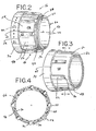
- FIG. 2 is a side perspective view of a clutch cap according to one embodiment of the present invention.
- FIG. 3 is side perspective view of a clutch cap according to another embodiment of the present invention.
- FIG. 4 ts a cross-sectional view of the clutch cap of FIG. 3 taken along line 4-4 of FIG. 3.
- FIG. 5 is a perspective view of a front sleeve according to one embodiment of the present invention.
- FIG. 6 is an exploded view of another embodiment of the front sleeve according to the present invention.
- FIG. 7 is a perspective view of a front sleeve according to another embodiment of the present invention.
- FIG. 8 is an enlarged view of a portion of the front sleeve of FIG. 7.
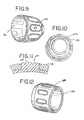
- FIG. 9 is a side perspective view of another embodiment of the front sleeve according to the present invention.
- FIG. 10 is a rear view of the sleeve of FIG. 9.
- FIG. 11 is an enlarged view of a portion of the front sleeve of FIG. 9.
- FIG. 12 is a perspective view of a rear sleeve according to one embodiment of the present invention.
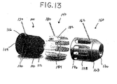
- FIG. 13 6 is an exploded view of another embodiment of the front sleeve according to the present invention.
- a rotary tool in the form of a drill is generally indicated at 10.
- the drill 10 includes a motor disposed in a housing.
- the motor is operable to drive a drive shaft.
- the drill 10 is battery-powered.
- the drill 10 may be powered by a conventional AC power source. Power is selectively supplied to the motor by pressing the trigger.
- the drill is conventional and does not form part of the present invention, except to the extent that the clutch cap and chuck assembly of the present invention are useful with a rotary tool such as the drill shown in FIG. 1.
- a clutch assembly is located at a position to with respect to the drive shaft to adjust the output torque.
- Clutch assemblies are known and the function and operation of the clutch assembly is not material to the clutch cap of the present invention.
- the clutch assembly includes a clutch mechanism 12 operatively associated with the drive shaft to adjust the output torque and a clutch cap 20 that surrounds at least a portion of the clutch mechanism 12.
- the clutch cap 20 is operatively associated with the clutch mechanism 12 such that rotation of the clutch cap 20 will adjust the output torque of the drive shaft.
- the clutch cap 20 is provided with indicia 22 to assist the user in adjusting the desired torque.
- the clutch cap 20 and grip assembly 16 will be described in more detail below.
- the drill also includes a chuck assembly 14 that is mounted to the drive shaft. It is to be understood that the chuck assembly 14 of the present invention may be used with other rotary-driven tools, and that the drill 10 illustrated in FIG. 1 is one example of such tools. For example, screw drivers, nut drivers, burrs, mounted grinding stones, and other cutting or abrading tools may employ embodiments of the present invention.
- the chuck assembly 14 includes a typical chuck mechanism having a chuck body member. It is believed that one skilled in the art can practice the subject application with any suitable mechanical chuck mechanism.
- the chuck body includes a forward section and a rearward section.
- a front sleeve 100 and a rear sleeve 190 incorporating the grip assembly 16 of the present invention surrounds the chuck mechanism.
- An axial bore is formed in the forward section of the chuck body.
- the axial bore is somewhat larger than the largest tool shank that the chuck mechanism is designed to accommodate.
- a threaded bore is formed in the rearward section of the chuck body, and is sized to mate with a threaded end of drive shaft. If desired, a tapered unthreaded bore sized to mate with a tapered drive shaft may replace the threaded bore.
- a plurality of jaws extends through passageways formed in the chuck body. Typically, three jaws are used and each jaw is separated from the adjacent jaws by an arc of 120°.
- the axes of the passageways and the jaws are angled with respect to the chuck body axis, and intersect the chuck body axis at a common point ahead of the chuck body.
- Each jaw has a tool-engaging surface that is generally parallel to the axis of the chuck body. Threads are located on the outer surface of each jaw.
- An adjustment ring encircles the chuck body and cooperates with the jaws.
- the threads are provided on the inner surface of the adjustment ring to mate with the threads on the jaw outer surfaces.
- the grip assembly 16 is defined by a clutch cap 20, a grip 40, and an optional cover 60.
- the clutch cap 20 is typically cylindrically shaped to surround the clutch mechanism 12 and conform to the overall appearance of the rotary tool 10.
- the clutch cap 20 includes inner sleeve 24 that may be formed by injection molding a hard plastic material such as a structural plastic such as polycarbonate, a filled polypropylene, e.g., glass-filled polypropylene, or a blend of structural materials.
- the inner sleeve 24 may be formed from stamped or formed metal.
- the inner sleeve 24 has a first end 26, a second end 28, and a peripheral wall 30 connecting the first 26 and second end 28.
- the first end 26 and the second end 28 define a longitudinal axis that extends through the first 26 and second ends 28.
- the first end 26 and the second end 28 are open to allow portions of the rotary tool such as the drive shaft to extend into and/or through the inner sleeve 24.
- the inner sleeve 24 has a diameter of a size sufficient to surround the clutch mechanism 12 (not shown).
- the first end 26 has a ledge 34 that has an outer periphery 36 with a diameter that is greater than the outer periphery 32 of the peripheral wall 30.
- the ledge 34 acts to stop longitudinal movement of the grip 40.
- the grip 40 is shown as cylindrically shaped. Although the grip 40 may have any suitable shape, typically it will be cylindrical to fit the cylindrical shape of the inner sleeve 24, which surrounds the clutch mechanism 12.
- the grip 40 has an open top 42 and an open bottom 44 opposite the open top 42 and defining a longitudinal axis 46 that is parallel to the longitudinal axis of the inner sleeve 24.
- a peripheral wall 48 connects the open top 42 and the open bottom 44. In the instance where the grip 40 is cylindrical, the peripheral wall 48 will be radial.
- the peripheral wall 48 has an outer surface 50 and ribs 52 that extend outward from the outer surface 50 to provide a gripping surface.
- the ribs 52 are shown as elongate members parallel to the longitudinal axis 46.
- the ribs 52 are located around at least a portion of the peripheral wall 48 and desirably are located around the entire portion of the peripheral wall 48.
- the ribs 52 are spaced apart to define a valley 54 between adjacent ribs. By providing alternating ribs 52 to define a valley 54, a better grip surface may be provided.
- the ribs 52 extend a portion of the distance from the bottom 44 to the top 42. As shown in FIG. 2, the ribs 52 extend the entire distance from the bottom 44 to the top 42. As shown in FIG. 3, the ribs 52 extend only a portion of the distance from the bottom 44 to the top 42.
- the bottom 44 of the grip 40 is adjacent the ledge 34.
- the ribs 52 do not extend radially outward a distance greater than the diameter of the outer surface 336 of the ledge 34 so that the clutch cap 20 presents a substantially uniform appearance.
- a 60 cover may be provided to cooperate with the grip 40 and to provide protection from wear to a substantial amount of the grip 40.
- the cover 60 is provided with an open top 62, an open bottom 64 and a peripheral wall 66 connecting the top 62 and the bottom 64.
- the bottom 64 is adjacent the first end 26 of the inner sleeve 24 and when the inner sleeve 24 is provided with a ledge 34, the bottom 64 of the cover 60 is adjacent the ledge 34.
- the wall 66 is provided with a plurality of spaced apart apertures 70 that receive respective ribs 52 of the grip 40.
- the ribs 52 may extend radially outward a distance beyond the top surface 68 of the cover 60, as best seen in FIG. 4.
- the ribs 52 may be sized such that they extend radially outward a distance that is substantially flush with the top surface 68 of the cover 60.
- the ribs 52 may be sized such that they extend radially outward a distance just below the top surface 68 of the cover 60.
- the top surface 53 of the ribs may have a concave shape to provide a depression to enhance the grippability of the clutch cap 20.
- the grip 40 is formed of a material that is softer than the material that is used for the tool housing so that the user can obtain a suitable grip to rotate the clutch cap 20. Where a cover 60 is provided, the grip 40 will likewise be formed of a material that is softer than the material is used for the cover 60. Desirably, the grip 40 is formed of an elastomeric material such as a natural or synthetic elastomer such as santoprene or vyram. The elastomeric material may have a hardness from Shore 45A durometer to Shore 50D durometer. A desirable hardness is about Shore 80A durometer.
- FIGs. 5-12 the grip assembly 16 for use with sleeves for a chuck assembly is shown.
- a grip assembly 16 for use as a front sleeve 100 of a chuck assembly 14 is shown.
- This grip assembly 16 includes a front sleeve 100 and a grip 140.
- FIG. 6 shows an exploded view of a grip assembly 16 useful for the front sleeve 100 of a chuck assembly 14.
- FIG. 7 shows an alternative grip assembly 16 in an assembled condition.
- the grip assembly 16 includes a front sleeve 100, a grip 140, and optionally, a cover 160.
- the front sleeve 100 is affixed to the chuck mechanism (not shown) or at least a portion of the chuck mechanism of the chuck assembly 14.
- the front sleeve 100 may be formed by injection molding a hard plastic material such as a structural plastic such as polycarbonate, a filled polypropylene, e.g., glass-filled polypropylene, or a blend of structural materials.
- the front sleeve 100 includes a first end 102 and a second end 108 with a peripheral wall 114 extending between the first end 102 and the second end 108.
- a longitudinal axis 122 is defined from the first end 102 to the second end 108.
- the first end 102 may be provided with a ledge 104 that has an outer periphery 106 with a diameter that is greater than the outer periphery 116 of the peripheral wall 114.
- the ledge 104 acts to stop longitudinal movement of the grip 140.
- the second end 108 may have a leading edge 110 that is tapered to define a nose 112.
- the outer surface 118 of the front sleeve 100 may be provided with a plurality of grooves 124 that are open at the second end 108 to receive complementary ribs 152 provided on the grip 140, as will be explained in more detail below.
- the grooves 124 need not be open at either end, and the complementary ribs 152 will be received within the grooves 124.
- the grooves 124 extend at least a portion from the second end 108 toward the first end 102.
- the grip 140 is shown as cylindrically shaped. Although the grip 140 may have any suitable shape, typically it will be cylindrical to fit the cylindrical shape of the front sleeve 100, which surrounds the chuck mechanism (not shown).
- the grip 140 is desirably formed of a material that is softer than the material of the front sleeve 100.
- the grip 140 is formed from an elastomeric material that may be formed of a natural or synthetic elastomer such as santoprene or vyram.
- the elastomeric material may have a hardness from Shore 45A durometer to Shore 50D durometer. A desirable hardness is about Shore 80A durometer.
- the grip 140 has an open top 142 and an open bottom 144 opposite the open top 142 and defining a longitudinal axis 146 that is parallel to the longitudinal axis of the front 100 sleeve.
- a peripheral wall 148 connects the open top 142 and the open bottom 144. In the instance where the grip 140 is cylindrical, the peripheral wall 148 will be radial.
- the distance between the top 142 and the bottom 144 of the grip 140 is such that the grip 140 covers a substantial portion of the front sleeve 100 from the first end 102 of the sleeve to the leading edge 110 at the second end 108 of the sleeve. It is to be understood, however, that the grip 140 may have any suitable length to provide a grip surface.
- the peripheral wall 148 has an outer surface 150 with ribs 152 that extend outward from the outer surface 150 to provide a gripping surface.
- the ribs 152 are shown as elongate members parallel to the longitudinal axis 146.
- the ribs 152 are located around at least a portion of the peripheral wall 148 and desirably are located around the entire portion of the peripheral wall 148.
- the ribs 152 are spaced apart such that adjacent ribs 152 define a valley 154. By providing alternating ribs 152 to define a valley 154 a better grip surface may be provided.
- the ribs 152 extend a portion of the distance from the bottom 144 to the top 142. As shown in FIG. 6, the ribs 152 extend the entire distance from the bottom 144 to the top 142.
- the ribs 152 may further be shaped to define a peripheral surface 156 that extends radially outward a distance greater than a top surface 153 of the ribs 152.
- the peripheral surface 156 of the ribs 152 defines a depression 157 within the peripheral surface 156 that will provide a gripping surface.
- the grip 140 has an inner surface 151 with a diameter about the same size as the diameter of the outer surface 118 of the front sleevel 00. Because the grip 140 is made of an elastomeric material, it can be stretched somewhat to place the grip 140 onto the outer surface 118 of the front sleeve 100. When in place, the elasticity of the grip 140 will position and hold the grip 140 onto the front sleeve 100. Alternatively, the grip 140 may be co-molded with the front sleeve 100 such that the grip 140 is integrally formed with the sleeve 100.
- the inner surface 151 of the grip 140 is provided with a plurality of complementary ribs 158 that will engage respective plurality of grooves 124 provided on the outer surface 118 of the front sleeve 100.
- the complementary ribs 158 and grooves 124 when engaged with each other, will minimize or limit rotational movement of the grip 140 with respect to the front sleeve 100.
- the grip 140 can be removed from the sleeve 100 when the grip is worn.
- the grip assembly 16 for sleeves optionally includes a cover 160.
- the cover 160 is made of a material that is harder than the material of the grip 140 to protect the grip 140 if the grip assembly 16 contacts a work surface or the like.
- the cover 160 may be made of relatively hard structural plastic or metal.
- the cover 160 may be formed from stamped metal.
- the cover 160 is shown with a first end 164 and a second end 166 with a peripheral wall 172 extending between the first end 164 and the second end 166.
- a longitudinal axis 174 is defined from the first end 164 to the second end 168.
- the peripheral wall 172 of the.cover 160 is provided with a plurality of apertures 176 to receive the ribs 152 of the grip 140 and through which the ribs 152 of the grip 140 may extend.
- the cover 160 surrounds the front sleeve 100 and is dimensioned such that the first end 164 of the cover 160 is adjacent the first end 102 of the front sleeve 100.
- the second end 166 of the cover 160 may have a leading edge 168 that is tapered to define a nose 170 that is adjacent to the nose 112 of the front sleeve 100.
- the first end 164 of the cover 160 may be provided with tabs or recesses (not shown) to engage with cooperating tabs or recesses 126 provided the first end 102 or on the ledge 104 to removably secure the cover 160 to the front sleeve 100.
- the exact configuration of such cooperating tabs or recesses is not important so long as the cover 160 can be removably secured to the front sleeve 100.
- the cover 160 is provided with apertures 128 that receive the ribs 152 of the grip 140.
- the ribs 152 may extend radially outward a distance beyond the top surface 162 of the cover 160.
- the ribs 152 and their peripheral sides 156 may extend radially outward such that they are substantially flush with the top surface 162 of the cover 160, as seen in FIG. 11.
- the ribs 152 may have a concave top surface 153, as best seen in FIG. 8 so that only the peripheral sides 156 are substantially flush with the top surface 162 of the cover 160.
- alternating sections of harder and softer material is provided (due to the alternating sections of the cover 160 and the ribs 152) to define a gripping surface.
- FIGs. 9-11 a unitary integrally molded front sleeve 100 according to one embodiment of the present invention is shown, with like reference numbers referring to like elements.
- the front sleeve 100 surrounds the grip.140.
- the front sleeve 100 is similar to that shown in FIG. 6, except it does not have grooves 124 to receive the grip. Instead, the front sleeve is provided with a plurality of apertures 128 to receive the ribs 152 of the grip 140 such the ribs 152 extend in a radially outward direction.
- the ribs 152 may extend outward in the same manner as described above.
- the ribs 152 may extend beyond the outer surface 118 of the sleeve 100, they may be flush with the cuter surface 118 of the sleeve 100, or they may be just below the outer surface 118 of the sleeve 100.
- the front sleeve 100 of this embodiment may be co-molded or made in a manner such that the grip 140, which is formed from an elastomeric material, can be applied to the inner surface 120 of the front sleeve 100 under conditions and in a manner such that the elastomeric material will flow into the apertures 128 of the sleeve 100.
- FIG. 13 shows another embodiment of the grip assembly 16 of the present invention as incorporated on a front sleeve 100 for a chuck assembly 14.
- the front sleeve 100 is provided with a plurality of depressions 130 about the circumference of the peripheral wall114.
- the depressions 130 receive complementary shaped ribs 180 that define a grip 140 with spaced apart ribs 180 extending generally circumferentially about the peripheral wall 114 of the front sleeve 140.
- the ribs 180 may be adhered or attached to the front sleeve such as by molding or other methods.
- the ribs 180 may also be provided with a flange 186 that surrounds the periphery of the ribs 180.
- the ribs may have a peripheral side wall 182 that defines a closed shape within which a valley 184 is defined. Surrounding the peripheral side wall of the ribs is a flange 186.
- a cover 160 surrounds the front sleeve 100 and is provided with apertures 176 such that a portion of the ribs 180 are received by the apertures 176 and another portion is contacted by the area surrounding the apertures 178 to assist in locating and maintaining the ribs 152 in place.
- the portion of the cover adjacent the aperture 178 will contact the flange 186 to hold the rib 180 in place.
- An optional rear sleeve 190 may be affixed to the chuck mechanism of the chuck assembly 14. If desired, the rear sleeve 190 may be omitted and the front sleeve 100 can extend to the rearward section of the chuck body. This alternative is feasible when a spindle lock is provided on the driver or when the driver motor is used to tighten or loosen the jaws.
- a rear sleeve 190 may incorporate the grip assembly 16 of the present invention in the same manner as described above with respect to the front sleeve 100 and the clutch cap 20.
- FIG. 12 shows an exemplary rear sleeve 190 incorporating the grip assembly 16 of the present invention.
- grip assembly 16 While certain embodiments of the grip assembly 16 have been described with respect to either the clutch cap 20 or the front sleeve 100, it should be understood that each embodiment can be used either with the clutch cap 20, the front sleeve 100, the rear sleeve 190, and any combination of them or all of them.
- the grip assembly 16 shown in FIG. 13 can be used with the clutch cap 20, the rear sleeve 190, or any combination of the front sleeve 100, the rear sleeve 190, the clutch cap 20, or all of them.
Landscapes
- Engineering & Computer Science (AREA)
- Mechanical Engineering (AREA)
- Golf Clubs (AREA)
- Manipulator (AREA)
- Dental Tools And Instruments Or Auxiliary Dental Instruments (AREA)
Applications Claiming Priority (2)
| Application Number | Priority Date | Filing Date | Title |
|---|---|---|---|
| US10/439,186 US7325812B2 (en) | 2003-05-14 | 2003-05-14 | Grip assembly for clutch cap, front sleeve, rear sleeve and method of making |
| US439186 | 2003-05-14 |
Publications (1)
| Publication Number | Publication Date |
|---|---|
| EP1477254A1 true EP1477254A1 (de) | 2004-11-17 |
Family
ID=33029810
Family Applications (1)
| Application Number | Title | Priority Date | Filing Date |
|---|---|---|---|
| EP04011380A Withdrawn EP1477254A1 (de) | 2003-05-14 | 2004-05-13 | Griff Anordnung für Kupplungskappe und vordere oder hintere Büchse |
Country Status (6)
| Country | Link |
|---|---|
| US (1) | US7325812B2 (de) |
| EP (1) | EP1477254A1 (de) |
| CN (1) | CN100486742C (de) |
| AU (1) | AU2004202031A1 (de) |
| CA (1) | CA2467219A1 (de) |
| NZ (1) | NZ532873A (de) |
Cited By (2)
| Publication number | Priority date | Publication date | Assignee | Title |
|---|---|---|---|---|
| GB2425279A (en) * | 2005-04-19 | 2006-10-25 | Jacobs Chuck Mfg Co | Chuck with a polymeric sleeve |
| US7222862B2 (en) * | 2001-10-26 | 2007-05-29 | Black & Decker Inc. | Tool holder |
Families Citing this family (8)
| Publication number | Priority date | Publication date | Assignee | Title |
|---|---|---|---|---|
| US7270910B2 (en) * | 2003-10-03 | 2007-09-18 | Black & Decker Inc. | Thermal management systems for battery packs |
| JP4153924B2 (ja) * | 2005-04-28 | 2008-09-24 | 株式会社ホンダアクセス | グリップ |
| DE102006005241A1 (de) * | 2006-02-06 | 2007-08-09 | Röhm Gmbh | Bohrfutter |
| US8011444B2 (en) * | 2009-04-03 | 2011-09-06 | Ingersoll Rand Company | Spindle locking assembly |
| CN101804626B (zh) * | 2010-03-30 | 2011-12-14 | 奇瑞汽车股份有限公司 | 自动变速箱离合器组件抓取工具及其专用检测工具 |
| US10226315B2 (en) * | 2015-06-30 | 2019-03-12 | Braun Gmbh | Multi-component plastic housing |
| US10583625B2 (en) * | 2015-06-30 | 2020-03-10 | Braun Gmbh | Plurality of mass-produced multi-component plastic housings |
| CN119655557B (zh) * | 2025-01-14 | 2026-04-03 | 山东亿福金业珠宝首饰有限公司 | 珠仔链车花机及珠仔链加工方法 |
Citations (3)
| Publication number | Priority date | Publication date | Assignee | Title |
|---|---|---|---|---|
| EP0495416A1 (de) * | 1991-01-18 | 1992-07-22 | Jacobs Chuck Technology Corporation | Verbesserte Schlüssellose Spannfutterhülse |
| US5882016A (en) * | 1997-07-17 | 1999-03-16 | Ryobi North America, Inc. | Soft grip keyless chuck assembly |
| US20020041072A1 (en) * | 1998-08-14 | 2002-04-11 | Larry Wilson | Chuck with locking sleeve |
Family Cites Families (50)
| Publication number | Priority date | Publication date | Assignee | Title |
|---|---|---|---|---|
| US911012A (en) * | 1908-03-16 | 1909-01-26 | Jacobs Mfg Co | Chuck. |
| US3189069A (en) * | 1963-12-06 | 1965-06-15 | Stanley Works | Tool handle with resilient gripping means |
| US3834252A (en) * | 1973-06-11 | 1974-09-10 | Black & Decker Mfg Co | Adjustable positive clutch screwdriver |
| US4460296A (en) * | 1981-06-04 | 1984-07-17 | Sivertson Jr Wilford E | Keyless chuck gripping device |
| US4575108A (en) * | 1983-09-28 | 1986-03-11 | Whitehead Dennis M | Drill chuck attachments |
| DE3418882A1 (de) * | 1984-05-21 | 1985-11-21 | Hilti Ag, Schaan | Staubschutzkappe |
| JPS6299007A (ja) * | 1985-10-25 | 1987-05-08 | Matsushita Electric Works Ltd | 締め付け具 |
| JPS62166906A (ja) * | 1986-01-21 | 1987-07-23 | Matsushita Electric Works Ltd | 締め付け具 |
| US4844488A (en) * | 1987-07-16 | 1989-07-04 | Flynn Jerome R | Chuck actuator system and method |
| US4817971A (en) * | 1987-07-16 | 1989-04-04 | Flynn Jerome R | Chuck actuator device and method |
| US5097566A (en) * | 1987-10-07 | 1992-03-24 | Bettcher Industries, Inc. | Slip-resistant cushioning covers for handles |
| US5476273A (en) * | 1989-12-11 | 1995-12-19 | Power Tool Holders Incorporated | Plastic grip boots for chucks |
| US5573254A (en) * | 1989-12-11 | 1996-11-12 | Power Tool Holders Incorporated | Non-impact keyless chuck |
| US5452906B1 (en) * | 1989-12-11 | 1997-07-29 | Power Tool Holders Inc | Non-impact keyless chuck |
| US5125673A (en) * | 1989-12-11 | 1992-06-30 | Huff Robert O | Non-impact keyless chuck |
| US5253879A (en) * | 1989-12-11 | 1993-10-19 | Jacobs Chuck Technology Corporation | Non-impact keyless chuck |
| US5025903A (en) * | 1990-01-09 | 1991-06-25 | Black & Decker Inc. | Dual mode rotary power tool with adjustable output torque |
| DE4038598C1 (de) * | 1990-12-04 | 1991-11-28 | Klaus 7312 Kirchheim De Lenhart | |
| US5261665A (en) * | 1992-02-11 | 1993-11-16 | Robert A. Paley, Inc. | Golf club grip formed of a plurality of materials and method of manufacture thereof |
| JP2721768B2 (ja) * | 1992-03-12 | 1998-03-04 | リョービ株式会社 | バッテリー式スクリュードライバー |
| US5280735A (en) * | 1992-05-01 | 1994-01-25 | Kuipers Raymond J | Two piece slip resistant grip |
| US5215317A (en) * | 1992-05-18 | 1993-06-01 | Jacobs Chuck Technology Corp. | Keyless chuck |
| DE4219253C2 (de) * | 1992-06-12 | 2001-04-26 | Werner Hermann Wera Werke | Heft für Werkzeuge, insbesondere Schraubendreher |
| US5341704A (en) * | 1993-01-15 | 1994-08-30 | Milwaukee Electric Tool Corporation | Depth adjustment assembly for power tool |
| US5531461A (en) * | 1993-09-27 | 1996-07-02 | Jacobs Chuck Technology Corporation | Chuck with torque limiting mechanism and inclined plane for final tightening |
| US5476019A (en) * | 1994-03-07 | 1995-12-19 | Sram Corporation | Rotatable handgrip actuating system |
| US5437524A (en) * | 1994-06-02 | 1995-08-01 | Huang; Jin-Tarn | Torque-adjustment controller |
| US5784935A (en) * | 1994-11-29 | 1998-07-28 | Gb Electrical, Inc. | Power operated torque driver for screw-on wire connectors |
| JP3152131B2 (ja) * | 1995-11-02 | 2001-04-03 | 日立工機株式会社 | 電池工具 |
| US5823069A (en) * | 1996-01-04 | 1998-10-20 | Harley-Davidson Motor Company | Resilient hand grip |
| USD386662S (en) * | 1996-01-16 | 1997-11-25 | Makita Corporation | Portable electric screwdriver |
| US5839163A (en) * | 1996-02-21 | 1998-11-24 | Vereinigte Stahlwarenfabrik Gebr. Richartz & Sohne GmbH | Grip-shell arrangement |
| USD382457S (en) * | 1996-03-14 | 1997-08-19 | Snap-On Technologies, Inc. | Cordless drill |
| US5730662A (en) * | 1996-10-21 | 1998-03-24 | Rens; Peter J. | Grip assembly and method |
| US6763747B1 (en) * | 1997-04-09 | 2004-07-20 | Emerson Electric Co. | Shock absorbing hammer and handle assembly |
| US6101895A (en) * | 1997-07-25 | 2000-08-15 | Shimano, Inc. | Grip for a bicycle shift control device |
| US6053675A (en) * | 1998-06-26 | 2000-04-25 | Black & Decker Inc. | Quick-acting tool bit holder |
| US6045303A (en) * | 1998-12-02 | 2000-04-04 | Chung; Lee Hsin-Chih | Rotatable torque adjusting device of rotation tool |
| USD429134S (en) * | 1999-08-13 | 2000-08-08 | S-B Power Tool Company | Powered hand-held drill driver |
| USD433909S (en) * | 1999-12-23 | 2000-11-21 | Ryobi North America, Inc. | Keyless drill chuck |
| USD434629S (en) * | 1999-12-23 | 2000-12-05 | Ryobi North America, Inc. | Keyless drill chuck |
| US20020054798A1 (en) * | 2000-02-10 | 2002-05-09 | One World Technologies, Inc. | Hand-held tool containing a removably attachable object sensor |
| USD440850S1 (en) * | 2000-03-09 | 2001-04-24 | Hitachi Koki Co., Ltd. | Portable electric screw driver |
| USD441268S1 (en) * | 2000-03-15 | 2001-05-01 | Choon Nang Electrical Appliance Mfy. Ltd. | Electric drill |
| US6408524B1 (en) * | 2000-06-16 | 2002-06-25 | Yin-Chu Lai | Tableware grip structure with comfortable touch feeling |
| US6488286B2 (en) * | 2000-08-21 | 2002-12-03 | Theodore G. Yaksich | Chuck and power driver having improved interface assembly |
| US6676557B2 (en) * | 2001-01-23 | 2004-01-13 | Black & Decker Inc. | First stage clutch |
| USD467481S1 (en) * | 2001-08-16 | 2002-12-24 | Black & Decker Inc. | Multi-purpose drill/driver |
| USD469675S1 (en) * | 2001-12-07 | 2003-02-04 | One World Technologies Limited | Cordless drill |
| JP4155751B2 (ja) * | 2002-03-20 | 2008-09-24 | 日立工機株式会社 | 電動工具 |
-
2003
- 2003-05-14 US US10/439,186 patent/US7325812B2/en not_active Expired - Fee Related
-
2004
- 2004-05-11 NZ NZ532873A patent/NZ532873A/en unknown
- 2004-05-13 CN CN200410044507.3A patent/CN100486742C/zh not_active Expired - Fee Related
- 2004-05-13 EP EP04011380A patent/EP1477254A1/de not_active Withdrawn
- 2004-05-13 AU AU2004202031A patent/AU2004202031A1/en not_active Abandoned
- 2004-05-13 CA CA002467219A patent/CA2467219A1/en not_active Abandoned
Patent Citations (3)
| Publication number | Priority date | Publication date | Assignee | Title |
|---|---|---|---|---|
| EP0495416A1 (de) * | 1991-01-18 | 1992-07-22 | Jacobs Chuck Technology Corporation | Verbesserte Schlüssellose Spannfutterhülse |
| US5882016A (en) * | 1997-07-17 | 1999-03-16 | Ryobi North America, Inc. | Soft grip keyless chuck assembly |
| US20020041072A1 (en) * | 1998-08-14 | 2002-04-11 | Larry Wilson | Chuck with locking sleeve |
Cited By (3)
| Publication number | Priority date | Publication date | Assignee | Title |
|---|---|---|---|---|
| US7222862B2 (en) * | 2001-10-26 | 2007-05-29 | Black & Decker Inc. | Tool holder |
| GB2425279A (en) * | 2005-04-19 | 2006-10-25 | Jacobs Chuck Mfg Co | Chuck with a polymeric sleeve |
| GB2425279B (en) * | 2005-04-19 | 2011-02-16 | Jacobs Chuck Mfg Co | Chuck with improved sleeve |
Also Published As
| Publication number | Publication date |
|---|---|
| AU2004202031A1 (en) | 2004-12-02 |
| US7325812B2 (en) | 2008-02-05 |
| US20040227308A1 (en) | 2004-11-18 |
| NZ532873A (en) | 2005-11-25 |
| CA2467219A1 (en) | 2004-11-14 |
| CN100486742C (zh) | 2009-05-13 |
| CN1589996A (zh) | 2005-03-09 |
Similar Documents
| Publication | Publication Date | Title |
|---|---|---|
| US9221105B2 (en) | Drill chuck | |
| US6196554B1 (en) | Locking chuck | |
| EP0722800B1 (de) | Schlüsselloses Futter | |
| US9358617B2 (en) | Chuck | |
| US5913524A (en) | Chuck with gripping mechanism stop | |
| US6045141A (en) | Molded chuck | |
| US20020014749A1 (en) | Non-impact keyless chuck | |
| US20090114410A1 (en) | Power tool guard | |
| US7325812B2 (en) | Grip assembly for clutch cap, front sleeve, rear sleeve and method of making | |
| US20030026670A1 (en) | Self-cleaning drill chuck | |
| US20090045594A1 (en) | Locking chuck | |
| US10556276B2 (en) | Locking chuck | |
| US5882016A (en) | Soft grip keyless chuck assembly | |
| US6168170B1 (en) | Chuck with jaw blade rotational stop | |
| US6505840B2 (en) | Quick change chuck | |
| US6648341B1 (en) | Chuck with helical jaw bite | |
| WO2002045890A2 (en) | Chuck with spring leg dust cover | |
| EP3525968A1 (de) | Spannfutter mit schlupfsicherung |
Legal Events
| Date | Code | Title | Description |
|---|---|---|---|
| PUAI | Public reference made under article 153(3) epc to a published international application that has entered the european phase |
Free format text: ORIGINAL CODE: 0009012 |
|
| AK | Designated contracting states |
Kind code of ref document: A1 Designated state(s): AT BE BG CH CY CZ DE DK EE ES FI FR GB GR HU IE IT LI LU MC NL PL PT RO SE SI SK TR |
|
| AX | Request for extension of the european patent |
Extension state: AL HR LT LV MK |
|
| 17P | Request for examination filed |
Effective date: 20050317 |
|
| AKX | Designation fees paid |
Designated state(s): AT BE BG CH CY CZ DE DK EE ES FI FR GB GR HU IE IT LI LU MC NL PL PT RO SE SI SK TR |
|
| 17Q | First examination report despatched |
Effective date: 20090519 |
|
| STAA | Information on the status of an ep patent application or granted ep patent |
Free format text: STATUS: THE APPLICATION IS DEEMED TO BE WITHDRAWN |
|
| 18D | Application deemed to be withdrawn |
Effective date: 20110428 |