EP1477285A2 - Kantenanleimmaschine für Holzpaneele oder dergleichen - Google Patents
Kantenanleimmaschine für Holzpaneele oder dergleichen Download PDFInfo
- Publication number
- EP1477285A2 EP1477285A2 EP04102143A EP04102143A EP1477285A2 EP 1477285 A2 EP1477285 A2 EP 1477285A2 EP 04102143 A EP04102143 A EP 04102143A EP 04102143 A EP04102143 A EP 04102143A EP 1477285 A2 EP1477285 A2 EP 1477285A2
- Authority
- EP
- European Patent Office
- Prior art keywords
- edging
- tank
- assembly
- withdrawing
- similar
- Prior art date
- Legal status (The legal status is an assumption and is not a legal conclusion. Google has not performed a legal analysis and makes no representation as to the accuracy of the status listed.)
- Withdrawn
Links
Images


Classifications
-
- B—PERFORMING OPERATIONS; TRANSPORTING
- B27—WORKING OR PRESERVING WOOD OR SIMILAR MATERIAL; NAILING OR STAPLING MACHINES IN GENERAL
- B27D—WORKING VENEER OR PLYWOOD
- B27D5/00—Other working of veneer or plywood specially adapted to veneer or plywood
- B27D5/003—Other working of veneer or plywood specially adapted to veneer or plywood securing a veneer strip to a panel edge
-
- B—PERFORMING OPERATIONS; TRANSPORTING
- B27—WORKING OR PRESERVING WOOD OR SIMILAR MATERIAL; NAILING OR STAPLING MACHINES IN GENERAL
- B27G—ACCESSORY MACHINES OR APPARATUS FOR WORKING WOOD OR SIMILAR MATERIALS; TOOLS FOR WORKING WOOD OR SIMILAR MATERIALS; SAFETY DEVICES FOR WOOD WORKING MACHINES OR TOOLS
- B27G11/00—Applying adhesives or glue to surfaces of wood to be joined
- B27G11/02—Glue vessels; Apparatus for warming or heating glue
Definitions
- the present invention relates to an edging assembly for edging wood panels or similar.
- the present invention relates to an edging assembly located at an edging station of an edging machine, and comprising a tank for containing glue; withdrawing means for withdrawing glue from the tank; and supporting means for supporting the tank beneath the withdrawing means.
- the withdrawing means are generally movable, with respect to the tank and in a substantially vertical direction, to and from a raised position, in which the withdrawing means release the tank to enable removal of the tank from the supporting means.
- the tank Since the tank is normally fairly heavy and located in a part of the edging machine which is difficult to reach, and since the glue must be kept at relatively high temperature, removing the tank from the supporting means is an extremely difficult job, so that the edging assembly takes a relatively long time to set up.
- an edging assembly for edging wood panels or similar, the assembly comprising a tank for containing glue; withdrawing means for withdrawing glue from said tank; and supporting means for supporting the tank in a work position in which the tank is located beneath said withdrawing means; and being characterized in that said supporting means are movable supporting means for moving the tank to and from said work position.
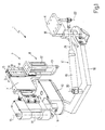
- Number 1 in the accompanying drawings indicates as a whole an edging assembly for edging wood panels or similar (not shown) and located at an edging station 2 of an edging machine (not shown), which also comprises a conveying device (not shown) for feeding the panels (not shown) successively through station 2 in a substantially horizontal direction 3, and a feed device (not shown) for feeding an edge (not shown) to station 2.
- Assembly 1 comprises a fixed frame 4 having a guide 5, which extends in a substantially vertical direction 6 crosswise to direction 3, and supports a slide 7 fitted in known manner to guide 5 to move linearly in direction 6 along guide 5 under the control of an actuating device 8 described in detail later on.
- Slide 7 supports a known withdrawal screw 9 (Figure 2) for withdrawing glue from tank 10, and which is fitted to slide 7 to rotate continuously, with respect to slide 7 and under the control of a known actuating device not shown, about a respective longitudinal axis 11 substantially parallel to direction 6.
- Device 8 comprises an actuating cylinder 12, which is fixed to frame 4, extends in direction 6, and has an output rod 13, a free end of which is fixed to slide 7 to move slide 7 between a lowered work position (Figure 1) in which screw 9 extends inside tank 10, and a raised rest position (Figure 2) in which screw 9 is entirely outside tank 10.
- Assembly 1 also comprises a known spreading roller 14 for receiving glue from screw 9 and spreading the glue onto the lateral edges of the panels (not shown), and which is fitted to slide 7 to rotate continuously, with respect to slide 7 and under the control of the same actuating device as screw 9, about a respective longitudinal axis 15 substantially parallel to axis 11.
- Tank 10 is fitted removably to a first free end of a substantially U-shaped supporting crank 16 hinged to frame 4 at a second free end to oscillate, with respect to frame 4 and under the control of an actuating device 17, about a hinge axis 18 substantially parallel to axes 11 and 15.
- device 17 comprises an actuating cylinder 19, which is hinged to crank 16 to oscillate, with respect to crank 16, about a hinge axis 20 substantially parallel to axis 18, comprises an output rod 21 hinged to frame 4 to oscillate, with respect to frame 4, about a hinge axis 22 substantially parallel to axis 20, and provides for moving tank 10, when slide 7 is in the raised rest position, between a work position ( Figure 2) in which tank 10 is located beneath screw 9, and a rest position ( Figure 3) in which tank 10 is located alongside screw 9 and detached completely from said device (not shown) for feeding said edge (not shown), so as to permit relatively troublefree maintenance and/or replacement of tank 10.
- actuating cylinder 19 which is hinged to crank 16 to oscillate, with respect to crank 16, about a hinge axis 20 substantially parallel to axis 18, comprises an output rod 21 hinged to frame 4 to oscillate, with respect to frame 4, about a hinge axis 22 substantially parallel to axis 20, and provides for moving tank 10, when slide 7 is in the raised rest position, between a work position (
- crank 16 is moved manually between the work and rest positions.
Landscapes
- Life Sciences & Earth Sciences (AREA)
- Engineering & Computer Science (AREA)
- Mechanical Engineering (AREA)
- Wood Science & Technology (AREA)
- Forests & Forestry (AREA)
- Coating Apparatus (AREA)
Applications Claiming Priority (2)
| Application Number | Priority Date | Filing Date | Title |
|---|---|---|---|
| ITBO20030303 | 2003-05-16 | ||
| ITBO20030303 ITBO20030303A1 (it) | 2003-05-16 | 2003-05-16 | Gruppo bordatore per la bordatura di pannelli di legno o simili. |
Publications (2)
| Publication Number | Publication Date |
|---|---|
| EP1477285A2 true EP1477285A2 (de) | 2004-11-17 |
| EP1477285A3 EP1477285A3 (de) | 2005-04-20 |
Family
ID=33017954
Family Applications (1)
| Application Number | Title | Priority Date | Filing Date |
|---|---|---|---|
| EP04102143A Withdrawn EP1477285A3 (de) | 2003-05-16 | 2004-05-14 | Kantenanleimmaschine für Holzpaneele oder dergleichen |
Country Status (2)
| Country | Link |
|---|---|
| EP (1) | EP1477285A3 (de) |
| IT (1) | ITBO20030303A1 (de) |
Cited By (3)
| Publication number | Priority date | Publication date | Assignee | Title |
|---|---|---|---|---|
| CN102114661A (zh) * | 2010-12-07 | 2011-07-06 | 东莞市南兴木工机械有限公司 | 自动封边机的螺杆泵式供胶装置 |
| ITMO20110131A1 (it) * | 2011-05-24 | 2012-11-25 | Scm Group Spa | Macchina bordatrice |
| CN111805682A (zh) * | 2020-07-14 | 2020-10-23 | 江苏力维智能装备有限公司 | 冷却固化反应型乙烯醋酸热熔胶高速封边机 |
Family Cites Families (4)
| Publication number | Priority date | Publication date | Assignee | Title |
|---|---|---|---|---|
| FR1510790A (fr) * | 1966-02-10 | 1968-01-19 | Stuttgarter Arbeitskreis Schre | Installation et procédé pour appliquer des revêtements de bords sur chant sur des plaques au moyen d'un adhésif ou d'une colle, ainsi que plaques conformes à cellesainsi obtenues |
| NL6804576A (de) * | 1968-04-02 | 1969-10-06 | ||
| DE3528019A1 (de) * | 1985-08-05 | 1987-02-12 | Erwin Haug Maschinenbau Gmbh | Beleimungsvorrichtung zum beleimen von stosskanten |
| IT1299931B1 (it) * | 1998-03-24 | 2000-04-04 | Scm Group Autec Division Spa | Dispositivo per la bordatura di pannelli. |
-
2003
- 2003-05-16 IT ITBO20030303 patent/ITBO20030303A1/it unknown
-
2004
- 2004-05-14 EP EP04102143A patent/EP1477285A3/de not_active Withdrawn
Cited By (5)
| Publication number | Priority date | Publication date | Assignee | Title |
|---|---|---|---|---|
| CN102114661A (zh) * | 2010-12-07 | 2011-07-06 | 东莞市南兴木工机械有限公司 | 自动封边机的螺杆泵式供胶装置 |
| CN102114661B (zh) * | 2010-12-07 | 2013-07-31 | 东莞市南兴家具装备制造股份有限公司 | 自动封边机的螺杆泵式供胶装置 |
| ITMO20110131A1 (it) * | 2011-05-24 | 2012-11-25 | Scm Group Spa | Macchina bordatrice |
| EP2527109A1 (de) * | 2011-05-24 | 2012-11-28 | SCM Group S.p.A. | Kantenanleimmaschine |
| CN111805682A (zh) * | 2020-07-14 | 2020-10-23 | 江苏力维智能装备有限公司 | 冷却固化反应型乙烯醋酸热熔胶高速封边机 |
Also Published As
| Publication number | Publication date |
|---|---|
| ITBO20030303A1 (it) | 2004-11-17 |
| EP1477285A3 (de) | 2005-04-20 |
Similar Documents
| Publication | Publication Date | Title |
|---|---|---|
| JP5212613B2 (ja) | 棒材供給機 | |
| CN106826365B (zh) | 一种棒料送料机 | |
| CN106031325B (zh) | 供料器更换装置 | |
| CN106241201B (zh) | 胶印机全自动上纸系统 | |
| US9539785B2 (en) | Box making machines | |
| CN113084884B (zh) | 一种创意产品包装设计用切割装置 | |
| JPH08216370A (ja) | 版板の準備のための方法と装置 | |
| US20080047407A1 (en) | Xy adjustment of a blade of a slicer | |
| EP2977326B1 (de) | Klebeband-kartonverschliessmaschinen | |
| EP1477285A2 (de) | Kantenanleimmaschine für Holzpaneele oder dergleichen | |
| KR100357936B1 (ko) | 벤딩된판유리이송장치 | |
| CN107179070B (zh) | 一种设有视觉系统的喷胶机 | |
| CN109894756A (zh) | 一种适用于软性材质的喷线切割机 | |
| US2944456A (en) | Automatic stitcher trimmer | |
| CN208194577U (zh) | 一种号牌销毁机 | |
| US4452115A (en) | Machine for treating plate-shaped workpieces especially a cutting press | |
| CN210823193U (zh) | 一种贴标机 | |
| US20050016341A1 (en) | Apparatus and method for cutting book blocks to size | |
| EP0899031A2 (de) | Vorrichtung zur Herstellung von Blechteilen mit abgekanteten Enden | |
| CN207771970U (zh) | 一种应用于模切设备的边框排废传送机构 | |
| CN208978428U (zh) | 一种锯片多色印刷固化装置 | |
| CN219116590U (zh) | 一种旋转带识别自动送料转角机设备 | |
| US20200255237A1 (en) | Device for Feeding a Sheet Product | |
| GB2072630A (en) | Replenishing feeder for folding machine | |
| KR102605918B1 (ko) | 스크라이빙 장치 |
Legal Events
| Date | Code | Title | Description |
|---|---|---|---|
| PUAI | Public reference made under article 153(3) epc to a published international application that has entered the european phase |
Free format text: ORIGINAL CODE: 0009012 |
|
| AK | Designated contracting states |
Kind code of ref document: A2 Designated state(s): AT BE BG CH CY CZ DE DK EE ES FI FR GB GR HU IE IT LI LU MC NL PL PT RO SE SI SK TR |
|
| AX | Request for extension of the european patent |
Extension state: AL HR LT LV MK |
|
| PUAL | Search report despatched |
Free format text: ORIGINAL CODE: 0009013 |
|
| AK | Designated contracting states |
Kind code of ref document: A3 Designated state(s): AT BE BG CH CY CZ DE DK EE ES FI FR GB GR HU IE IT LI LU MC NL PL PT RO SE SI SK TR |
|
| AX | Request for extension of the european patent |
Extension state: AL HR LT LV MK |
|
| 17P | Request for examination filed |
Effective date: 20051018 |
|
| AKX | Designation fees paid |
Designated state(s): AT BE BG CH CY CZ DE DK EE ES FI FR GB GR HU IE IT LI LU MC NL PL PT RO SE SI SK TR |
|
| 17Q | First examination report despatched |
Effective date: 20070830 |
|
| GRAP | Despatch of communication of intention to grant a patent |
Free format text: ORIGINAL CODE: EPIDOSNIGR1 |
|
| STAA | Information on the status of an ep patent application or granted ep patent |
Free format text: STATUS: THE APPLICATION IS DEEMED TO BE WITHDRAWN |
|
| 18D | Application deemed to be withdrawn |
Effective date: 20120131 |