EP1477343A2 - Système de suspension pour véhicule avec hauteur de châssis variable - Google Patents
Système de suspension pour véhicule avec hauteur de châssis variable Download PDFInfo
- Publication number
- EP1477343A2 EP1477343A2 EP04007990A EP04007990A EP1477343A2 EP 1477343 A2 EP1477343 A2 EP 1477343A2 EP 04007990 A EP04007990 A EP 04007990A EP 04007990 A EP04007990 A EP 04007990A EP 1477343 A2 EP1477343 A2 EP 1477343A2
- Authority
- EP
- European Patent Office
- Prior art keywords
- spring
- stop
- vehicle
- damper
- housing
- Prior art date
- Legal status (The legal status is an assumption and is not a legal conclusion. Google has not performed a legal analysis and makes no representation as to the accuracy of the status listed.)
- Granted
Links
- 239000000725 suspension Substances 0.000 title claims description 39
- 238000006073 displacement reaction Methods 0.000 claims abstract description 58
- 239000006096 absorbing agent Substances 0.000 claims abstract description 28
- 230000035939 shock Effects 0.000 claims abstract description 28
- 238000012546 transfer Methods 0.000 claims description 2
- 230000007935 neutral effect Effects 0.000 description 8
- 230000003068 static effect Effects 0.000 description 7
- 230000008859 change Effects 0.000 description 6
- 238000013461 design Methods 0.000 description 6
- 238000000034 method Methods 0.000 description 5
- 230000008569 process Effects 0.000 description 5
- 238000007789 sealing Methods 0.000 description 5
- 230000000694 effects Effects 0.000 description 3
- 238000009434 installation Methods 0.000 description 3
- 230000006835 compression Effects 0.000 description 2
- 238000007906 compression Methods 0.000 description 2
- 239000012530 fluid Substances 0.000 description 2
- 125000006850 spacer group Chemical group 0.000 description 2
- 230000009471 action Effects 0.000 description 1
- 238000011161 development Methods 0.000 description 1
- 238000005516 engineering process Methods 0.000 description 1
- 230000000750 progressive effect Effects 0.000 description 1
- 230000004044 response Effects 0.000 description 1
- 238000012549 training Methods 0.000 description 1
Images


Classifications
-
- B—PERFORMING OPERATIONS; TRANSPORTING
- B60—VEHICLES IN GENERAL
- B60G—VEHICLE SUSPENSION ARRANGEMENTS
- B60G17/00—Resilient suspensions having means for adjusting the spring or vibration-damper characteristics, for regulating the distance between a supporting surface and a sprung part of vehicle or for locking suspension during use to meet varying vehicular or surface conditions, e.g. due to speed or load
- B60G17/02—Spring characteristics, e.g. mechanical springs and mechanical adjusting means
- B60G17/04—Spring characteristics, e.g. mechanical springs and mechanical adjusting means fluid spring characteristics
- B60G17/044—Self-pumping fluid springs
-
- B—PERFORMING OPERATIONS; TRANSPORTING
- B60—VEHICLES IN GENERAL
- B60G—VEHICLE SUSPENSION ARRANGEMENTS
- B60G17/00—Resilient suspensions having means for adjusting the spring or vibration-damper characteristics, for regulating the distance between a supporting surface and a sprung part of vehicle or for locking suspension during use to meet varying vehicular or surface conditions, e.g. due to speed or load
- B60G17/02—Spring characteristics, e.g. mechanical springs and mechanical adjusting means
- B60G17/027—Mechanical springs regulated by fluid means
- B60G17/0272—Mechanical springs regulated by fluid means the mechanical spring being a coil spring
-
- F—MECHANICAL ENGINEERING; LIGHTING; HEATING; WEAPONS; BLASTING
- F16—ENGINEERING ELEMENTS AND UNITS; GENERAL MEASURES FOR PRODUCING AND MAINTAINING EFFECTIVE FUNCTIONING OF MACHINES OR INSTALLATIONS; THERMAL INSULATION IN GENERAL
- F16F—SPRINGS; SHOCK-ABSORBERS; MEANS FOR DAMPING VIBRATION
- F16F9/00—Springs, vibration-dampers, shock-absorbers, or similarly-constructed movement-dampers using a fluid or the equivalent as damping medium
- F16F9/32—Details
- F16F9/3207—Constructional features
- F16F9/3235—Constructional features of cylinders
- F16F9/3242—Constructional features of cylinders of cylinder ends, e.g. caps
-
- F—MECHANICAL ENGINEERING; LIGHTING; HEATING; WEAPONS; BLASTING
- F16—ENGINEERING ELEMENTS AND UNITS; GENERAL MEASURES FOR PRODUCING AND MAINTAINING EFFECTIVE FUNCTIONING OF MACHINES OR INSTALLATIONS; THERMAL INSULATION IN GENERAL
- F16F—SPRINGS; SHOCK-ABSORBERS; MEANS FOR DAMPING VIBRATION
- F16F9/00—Springs, vibration-dampers, shock-absorbers, or similarly-constructed movement-dampers using a fluid or the equivalent as damping medium
- F16F9/32—Details
- F16F9/36—Special sealings, including sealings or guides for piston-rods
- F16F9/362—Combination of sealing and guide arrangements for piston rods
-
- F—MECHANICAL ENGINEERING; LIGHTING; HEATING; WEAPONS; BLASTING
- F16—ENGINEERING ELEMENTS AND UNITS; GENERAL MEASURES FOR PRODUCING AND MAINTAINING EFFECTIVE FUNCTIONING OF MACHINES OR INSTALLATIONS; THERMAL INSULATION IN GENERAL
- F16F—SPRINGS; SHOCK-ABSORBERS; MEANS FOR DAMPING VIBRATION
- F16F9/00—Springs, vibration-dampers, shock-absorbers, or similarly-constructed movement-dampers using a fluid or the equivalent as damping medium
- F16F9/32—Details
- F16F9/48—Arrangements for providing different damping effects at different parts of the stroke
- F16F9/49—Stops limiting fluid passage, e.g. hydraulic stops or elastomeric elements inside the cylinder which contribute to changes in fluid damping
-
- F—MECHANICAL ENGINEERING; LIGHTING; HEATING; WEAPONS; BLASTING
- F16—ENGINEERING ELEMENTS AND UNITS; GENERAL MEASURES FOR PRODUCING AND MAINTAINING EFFECTIVE FUNCTIONING OF MACHINES OR INSTALLATIONS; THERMAL INSULATION IN GENERAL
- F16F—SPRINGS; SHOCK-ABSORBERS; MEANS FOR DAMPING VIBRATION
- F16F9/00—Springs, vibration-dampers, shock-absorbers, or similarly-constructed movement-dampers using a fluid or the equivalent as damping medium
- F16F9/32—Details
- F16F9/58—Stroke limiting stops, e.g. arranged on the piston rod outside the cylinder
Definitions
- the invention relates to a vehicle suspension system with changeable Height of the vehicle body compared to a wheel guide element, with a suspension spring and a shock absorber, which is a tension stop spring has that with a correspondingly strong rebound of the suspension spring with a interacts in different positions.
- a suspension spring and a shock absorber which is a tension stop spring has that with a correspondingly strong rebound of the suspension spring with a interacts in different positions.
- the position of the stop is thus generally speaking for the tension stop spring so changeable that the latter regardless of respective height of the vehicle body the (dynamic) suspension travel the suspension spring alone leaves essentially unchanged, i.e. that practical at each of the possible levels, the tension stop spring after an im essentially the same spring travel of the suspension spring at the stop Concern comes and only then becomes effective.
- This shift of The stop of the tension stop spring should automatically change of the static altitude level, without doing this elaborate or in an elaborate manner controllable adjustment units required are.
- This adjustment spring element is a second so-called distance spring element, that is supported between the stop and the tension stop spring is opposite.
- shock absorber the so-called. wheel guide element for the sprung vehicle wheel
- the tension stop spring within the Damper housing practically on the piston rod of the shock absorber guided and supported with one end, for example, on the damper piston is arranged that after a certain deflection of the air spring / suspension spring (from the neutral position) the tension stop spring with its at the other end to a stop fixed to the damper housing comes.
- the support space of the support cylinder goes hand in hand with a displacement or displacement of the displacement piston is filled with additional hydraulic medium or that part of the Hydraulic medium is discharged from the support room.
- Support cylinder with the support space in this and it can act as a hydraulic medium advantageously the hydraulic medium of the usually hydraulic Shock absorber can be used.
- a suitable, in particular suitably dimensioned, can be used for this Hydraulic line may be provided.
- Hydraulic space of the shock absorber can be a suitable throttle element be provided, which is dimensioned such that only one relative or very slow displacement of the displacement piston is possible.
- the tension stop spring as soon as it with the Shift piston provided or supported stop in contact comes, actually on the located in the support chamber of the support cylinder Hydraulic medium can support without this force the displacement piston (and thus the stop) immediately noteworthy is moved.
- the free flow cross-section of the throttle element specifically designed to be changeable (i.e.
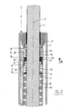
- FIGS. 1, 2 only showing the essential elements of a preferred exemplary embodiment of a vehicle suspension system according to the invention in a first design at two different levels of the vehicle body, while in FIG second type or embodiment are shown.
- Reference number 1 denotes the housing of a hydraulic shock absorber installed in the chassis of a motor vehicle, within which, as usual, a damper piston 2, which is only visible in FIG . 3, is guided so as to be longitudinally displaceable in the direction of the longitudinal axis 3 of the shock absorber. While the associated damper piston rod 4, which is led out of the damper housing 1, is articulated with its upper free end (not shown (both in the figures and in the installation situation)) on the vehicle body, also not shown, the damper housing 1 functions as Wheel guide element and thus guides or carries, via suitable intermediate elements, a wheel of the motor vehicle with its lower end (both in the figures and in the installation situation).
- the cylindrical damper housing 1 is closed off by means of a terminating bushing 5 which enables the passage of the piston rod 4 with the interposition of a suitable sealing arrangement, through which a so-called (via a suitable shoulder) in the interior of the housing 1.
- Guide cylinder 6 is positioned, which extends in both exemplary embodiments substantially over the entire length of the housing 1.
- the damper piston 2 is guided within this or through this guide cylinder (s) 6.
- 3 shows the connection of the piston rod 4 to the damper piston 2.
- tension stop spring 7 (which is basically known to the person skilled in the art and explained in terms of its function in the introductory description), which is arranged or guided in the annular space 8 between the damper piston rod 4 and the guide cylinder 6.
- this tension stop spring 7 is supported with its lower end (not shown in the figure) on the damper piston (2), also not shown in the figure.
- On the opposite upper end of the tension stop spring 7 is also placed in the annular space 8 along the longitudinal axis 3 supporting disc 9.
- this displacement piston 10 is guided both by the piston rod 4 and by the guide cylinder 6, with suitable ring sealing elements 13 being provided in the displacement piston 10 both to the piston rod 4 and to the guide cylinder 6.
- These ring sealing elements 13 serve to seal a so-called support space 14 which is located on the side of the displacement piston 10 facing away from the spacing spring element 12.
- This support space 14 is limited by the displacement piston 10 in cooperation with the guide cylinder 6 and the terminating bush 5.
- the corresponding section of the guide cylinder 6 guiding the displacement piston 6 and thereby delimiting the said support space 14, as well as the section of the end bushing 5, which also delimits the support space 14, are henceforth referred to as so-called support cylinders 6 ', which like is clearly open towards the bottom.
- a so-called readjustment formed in the support space 14 between the bottom of the so-called support cylinder 6 ', ie the end bushing 5, and the displacement piston 10 is designed as a helical compression spring.
- Spring element 11 clamped or supported.
- a hydraulic line 15 also opens into the support space 14, which continues in the annular space 19 between the damper housing 1 and the guide cylinder 6 and finally, for example, opens below the damper piston (2) in a space in the shock absorber in which there is always hydraulic medium of the hydraulic shock absorber is under low pressure. This ensures that the support space 14 is almost always completely filled with the hydraulic medium (the shock absorber) via the hydraulic line 15.
- a throttle element 16 designed here as a cross-sectional constriction is also provided, the function of which will be discussed further below.
- the displacement piston 6 It has an annular base section which bears on the outside on the guide cylinder 6 or on the support cylinder 6 'and on the inside on the piston rod 4. From this bottom section protrudes in the direction of the support disk 9 towards an annular web 17, the free end of which acts as a stop for the support disk 9 (and thus for the tension stop spring 6), as will be explained in more detail below, which is why this annular web 17 in the following is also referred to as stop 17.
- the shock absorber is shown in the so-called neutral position, in which the vehicle body is neither sprung nor sprung against the wheel guide element, ie the damper housing 1.
- the damper piston (2) and thus the piston rod 4 are moved according to the position shown in the illustration The direction of the arrow 18 moves upwards, the tension stop spring 7 being carried undeformed until the support disk 9 comes to rest against the stop 17.
- the displacement piston 10 cannot be displaced in the direction of the arrow 18 for a short time due to the hydraulic medium in the support chamber 14, then with further dynamic rebounding of the aforementioned suspension spring, ie with a further displacement of the piston rod 4 in accordance with the arrow direction 18, this is caused by the Driving operation of the vehicle, the tension stop spring 7 is compressed, so that the tension spring 7 is thereby connected in parallel to the support spring.
- the throttle element 16 in the hydraulic line 15 ensures that the displacement piston 10 is essentially not displaced in the direction of the arrow 18 in this process. This prevents namely that a noteworthy amount of hydraulic medium is discharged from the support space 14 for a short time, but this would be necessary for a corresponding displacement of the displacement piston 10.
- a shock absorber designed according to the previous explanations is now installed in a motor vehicle with a variable height, in which the distance I between the vehicle body (not shown) and the wheel guiding element, for example the upper edge of the damper housing 1, can be statically changed.
- the free rebound path of the suspension spring, not shown is characterized by the distance x without the tension stop spring 7 taking effect, i.e. when the suspension spring is dynamically rebounded during driving operation, the damper piston, not shown here, can be shown (2) are shifted upwards by the distance x in the direction of the arrow 18 until the support disk 9 and thus quasi the tension stop spring 7 comes to rest against the stop 17 and is then effective.
- Said first readjustment spring element 11 and said second distance spring element 12 are thus designed such that the desired free rebound path x between the stop 7 occurs independently of the respective level without dynamic driving processes, ie in the static state with the body in neutral position , which is determined by the position of the displacement piston 10, and the tension stop spring 7 adjusts itself.
- the system described so far with reference to FIGS. 1, 2 is a passive system; However, an active system is also possible if a volume flow of hydraulic medium from or into the support space 14 is made changeable or is prevented at all by a corresponding, for example, electrically switchable valve.
- FIG. 3 Another exemplary embodiment is shown in FIG. 3 , with here an independent support cylinder 6 ′ which is independent of the guide cylinder 6 and which is closed towards the vehicle wheel, ie downwards, and open to the vehicle body, ie upwards, and the damper Surrounding the piston rod 4 is provided near or just above the damper piston 2.
- a displacement piston 10 is also guided in the direction of the longitudinal axis 3 within the support cylinder 6 ', the displacement piston 10 shown here having a guide for the spacer spring element 12. This extends from the displacement piston 10 to the support disk 9, which likewise has a guide for this spring element 12 and on which the tension stop spring 7 rests.
- a static change in the level and thus the distance dimension I 'between the damper housing 1 and the vehicle body, which is different here compared to FIG. This takes place via a defined narrow annular gap 20 between the displacement piston 10 and the damper piston rod 4.
- the displacement piston 10 is guided solely through the support cylinder 6 ′ in FIG. 3 and no ring sealing elements (reference number 13 in FIG. 1, 2) are provided between these components.
Landscapes
- Engineering & Computer Science (AREA)
- General Engineering & Computer Science (AREA)
- Mechanical Engineering (AREA)
- Vehicle Body Suspensions (AREA)
- Fluid-Damping Devices (AREA)
Applications Claiming Priority (2)
| Application Number | Priority Date | Filing Date | Title |
|---|---|---|---|
| DE10321997 | 2003-05-16 | ||
| DE2003121997 DE10321997A1 (de) | 2003-05-16 | 2003-05-16 | Fahrzeug-Federungssystem mit veränderbarem Höhenstand des Fahrzeug-Aufbaus |
Publications (3)
| Publication Number | Publication Date |
|---|---|
| EP1477343A2 true EP1477343A2 (fr) | 2004-11-17 |
| EP1477343A3 EP1477343A3 (fr) | 2004-12-22 |
| EP1477343B1 EP1477343B1 (fr) | 2006-06-21 |
Family
ID=33016418
Family Applications (1)
| Application Number | Title | Priority Date | Filing Date |
|---|---|---|---|
| EP20040007990 Expired - Lifetime EP1477343B1 (fr) | 2003-05-16 | 2004-04-01 | Système de suspension pour véhicule avec hauteur de châssis variable |
Country Status (2)
| Country | Link |
|---|---|
| EP (1) | EP1477343B1 (fr) |
| DE (2) | DE10321997A1 (fr) |
Cited By (7)
| Publication number | Priority date | Publication date | Assignee | Title |
|---|---|---|---|---|
| EP1593874A1 (fr) * | 2004-05-03 | 2005-11-09 | DaimlerChrysler AG | Amortisseur de vibrations avec butée de traction |
| GB2417999A (en) * | 2004-09-09 | 2006-03-15 | Tenneco Automotive Operating | A shock absorber having a hydraulic stop |
| WO2013050205A1 (fr) * | 2011-10-06 | 2013-04-11 | Bayerische Motoren Werke Aktiengesellschaft | Suspension de roue de véhicule pourvue d'un amortisseur de vibrations hydraulique |
| FR3010161A1 (fr) * | 2013-08-29 | 2015-03-06 | Peugeot Citroen Automobiles Sa | Butee d'attaque de suspension d'un vehicule automobile, comportant un reglage automatique de hauteur |
| CN104494362A (zh) * | 2014-12-21 | 2015-04-08 | 苏州路云机电设备有限公司 | 一种柔性轨夹紧走行轮 |
| WO2019020625A1 (fr) * | 2017-07-26 | 2019-01-31 | Bayerische Motoren Werke Aktiengesellschaft | Système d'amortisseur et de suspension d'une roue de véhicule |
| US20210180662A1 (en) * | 2019-12-11 | 2021-06-17 | Kyb Europe Gmbh, Sucursal En Navarra | Variable load hydraulic control device |
Families Citing this family (2)
| Publication number | Priority date | Publication date | Assignee | Title |
|---|---|---|---|---|
| DE102009057165A1 (de) * | 2009-12-05 | 2011-06-09 | Volkswagen Ag | Anschlagpatrone für einen Schwingungsdämpfer |
| CN111927915B (zh) * | 2020-07-03 | 2021-08-24 | 中国船舶重工集团公司第七0四研究所 | 一种用于潜水器布放回收作业的阻尼缓冲器 |
Citations (1)
| Publication number | Priority date | Publication date | Assignee | Title |
|---|---|---|---|---|
| DE10121918A1 (de) | 2001-05-05 | 2002-11-28 | Daimler Chrysler Ag | Feder-Dämpfer-System mit federndem Anschlag |
Family Cites Families (4)
| Publication number | Priority date | Publication date | Assignee | Title |
|---|---|---|---|---|
| US5009451A (en) * | 1988-07-19 | 1991-04-23 | Kabushiki Kaisha Showa Seisakusho | Shock absorber for use in a vehicle |
| DE19935865B4 (de) * | 1999-07-30 | 2009-10-22 | Audi Ag | Vorrichtung zum Verändern der Federrate |
| JP2001191776A (ja) * | 2000-01-11 | 2001-07-17 | Toyota Motor Corp | 車両の姿勢変化規制装置 |
| DE10245362A1 (de) * | 2002-09-28 | 2004-04-08 | Dr.Ing.H.C. F. Porsche Ag | Verstellbares Federbein für Kraftfahrzeuge |
-
2003
- 2003-05-16 DE DE2003121997 patent/DE10321997A1/de not_active Withdrawn
-
2004
- 2004-04-01 EP EP20040007990 patent/EP1477343B1/fr not_active Expired - Lifetime
- 2004-04-01 DE DE200450000801 patent/DE502004000801D1/de not_active Expired - Lifetime
Patent Citations (1)
| Publication number | Priority date | Publication date | Assignee | Title |
|---|---|---|---|---|
| DE10121918A1 (de) | 2001-05-05 | 2002-11-28 | Daimler Chrysler Ag | Feder-Dämpfer-System mit federndem Anschlag |
Cited By (13)
| Publication number | Priority date | Publication date | Assignee | Title |
|---|---|---|---|---|
| EP1593874A1 (fr) * | 2004-05-03 | 2005-11-09 | DaimlerChrysler AG | Amortisseur de vibrations avec butée de traction |
| GB2417999A (en) * | 2004-09-09 | 2006-03-15 | Tenneco Automotive Operating | A shock absorber having a hydraulic stop |
| US7032727B2 (en) | 2004-09-09 | 2006-04-25 | Tenneco Automotive Operating Company Inc. | Shock absorber having a hydraulic stop |
| US7156213B2 (en) | 2004-09-09 | 2007-01-02 | Tenneco Automotive Operating Company Inc. | Shock absorber having a hydraulic stop |
| GB2417999B (en) * | 2004-09-09 | 2009-05-06 | Tenneco Automotive Operating | Shock absorber having hydraulic stop |
| US9090141B2 (en) | 2011-10-06 | 2015-07-28 | Bayerische Motoren Werke Aktiengesellschaft | Vehicle wheel suspension with a hydraulic vibration damper |
| WO2013050205A1 (fr) * | 2011-10-06 | 2013-04-11 | Bayerische Motoren Werke Aktiengesellschaft | Suspension de roue de véhicule pourvue d'un amortisseur de vibrations hydraulique |
| FR3010161A1 (fr) * | 2013-08-29 | 2015-03-06 | Peugeot Citroen Automobiles Sa | Butee d'attaque de suspension d'un vehicule automobile, comportant un reglage automatique de hauteur |
| CN104494362A (zh) * | 2014-12-21 | 2015-04-08 | 苏州路云机电设备有限公司 | 一种柔性轨夹紧走行轮 |
| WO2019020625A1 (fr) * | 2017-07-26 | 2019-01-31 | Bayerische Motoren Werke Aktiengesellschaft | Système d'amortisseur et de suspension d'une roue de véhicule |
| US11192419B2 (en) | 2017-07-26 | 2021-12-07 | Bayerische Motoren Werke Aktiengesellschaft | Bearing spring/damper system of a vehicle wheel |
| US20210180662A1 (en) * | 2019-12-11 | 2021-06-17 | Kyb Europe Gmbh, Sucursal En Navarra | Variable load hydraulic control device |
| US11592073B2 (en) * | 2019-12-11 | 2023-02-28 | Kyb Europe Gmbh, Sucursal En Navarra | Variable load hydraulic control device |
Also Published As
| Publication number | Publication date |
|---|---|
| EP1477343B1 (fr) | 2006-06-21 |
| DE502004000801D1 (de) | 2006-08-03 |
| EP1477343A3 (fr) | 2004-12-22 |
| DE10321997A1 (de) | 2004-12-02 |
Similar Documents
| Publication | Publication Date | Title |
|---|---|---|
| DE10025399C2 (de) | Schwingungsdämpfer | |
| EP0300204B1 (fr) | Amortisseur | |
| EP3137320B1 (fr) | Amortisseur de vibrations pour roue de véhicule | |
| DE19805957C2 (de) | Verstellbarer Stoßdämpfer | |
| DE3536867C2 (de) | Federbein für eine Fahrzeugradaufhängung | |
| DE112013004595B4 (de) | Aufhängungsvorrichtung | |
| DE2239444A1 (de) | Radaufhaengung fuer zweiradfahrzeuge | |
| DE4018712A1 (de) | Luftfeder mit umschaltbarer federsteifigkeit | |
| EP1831582B1 (fr) | Unite d'amortissement a ressort pneumatique | |
| WO2020001962A1 (fr) | Suspension de roue de véhicule avec un système de positionnement pour le pied d'un ressort porteur de carrosserie | |
| DE19731139A1 (de) | Kolben-Zylinder-Aggregat, das zwischen einem Aufbau und einem Radführungsteil eines Fahrzeugs eingebaut ist | |
| DE2754777C2 (de) | Federbein für ein Fahrzeug | |
| DE3523912A1 (de) | Achsaufhaengung fuer kraftfahrzeuge, insbesondere fuer personenkraftwagen | |
| DE7321271U (de) | Niveauregelnde Aufhängung für Fahrzeuge, insbesondere Kraftfahrzeuge | |
| EP1477343B1 (fr) | Système de suspension pour véhicule avec hauteur de châssis variable | |
| DE102006025826B4 (de) | Selbstpumpendes hydropneumatisches Federbein | |
| DE3346660C2 (fr) | ||
| EP1837548A1 (fr) | Unité d'amortissement et de ressort à air dotée d'un pli roulé détendu | |
| WO2019020625A1 (fr) | Système d'amortisseur et de suspension d'une roue de véhicule | |
| DE102006008608B4 (de) | Radaufhängung | |
| DE3935608A1 (de) | Kolbenzylindereinheit | |
| DE3601445C2 (fr) | ||
| DE3330815C2 (fr) | ||
| DE4035313C2 (de) | System zum Regeln eines Fahrwerkes | |
| EP2476930B1 (fr) | Système d'amortissement à ressort, en particulier pour une suspension de roue d'un véhicule |
Legal Events
| Date | Code | Title | Description |
|---|---|---|---|
| PUAI | Public reference made under article 153(3) epc to a published international application that has entered the european phase |
Free format text: ORIGINAL CODE: 0009012 |
|
| PUAL | Search report despatched |
Free format text: ORIGINAL CODE: 0009013 |
|
| AK | Designated contracting states |
Kind code of ref document: A2 Designated state(s): AT BE BG CH CY CZ DE DK EE ES FI FR GB GR HU IE IT LI LU MC NL PL PT RO SE SI SK TR |
|
| AX | Request for extension of the european patent |
Extension state: AL HR LT LV MK |
|
| AK | Designated contracting states |
Kind code of ref document: A3 Designated state(s): AT BE BG CH CY CZ DE DK EE ES FI FR GB GR HU IE IT LI LU MC NL PL PT RO SE SI SK TR |
|
| AX | Request for extension of the european patent |
Extension state: AL HR LT LV MK |
|
| 17P | Request for examination filed |
Effective date: 20041127 |
|
| 17Q | First examination report despatched |
Effective date: 20050513 |
|
| AKX | Designation fees paid |
Designated state(s): DE FR GB IT |
|
| GRAP | Despatch of communication of intention to grant a patent |
Free format text: ORIGINAL CODE: EPIDOSNIGR1 |
|
| GRAS | Grant fee paid |
Free format text: ORIGINAL CODE: EPIDOSNIGR3 |
|
| GRAA | (expected) grant |
Free format text: ORIGINAL CODE: 0009210 |
|
| AK | Designated contracting states |
Kind code of ref document: B1 Designated state(s): DE FR GB IT |
|
| PG25 | Lapsed in a contracting state [announced via postgrant information from national office to epo] |
Ref country code: IT Free format text: LAPSE BECAUSE OF FAILURE TO SUBMIT A TRANSLATION OF THE DESCRIPTION OR TO PAY THE FEE WITHIN THE PRESCRIBED TIME-LIMIT;WARNING: LAPSES OF ITALIAN PATENTS WITH EFFECTIVE DATE BEFORE 2007 MAY HAVE OCCURRED AT ANY TIME BEFORE 2007. THE CORRECT EFFECTIVE DATE MAY BE DIFFERENT FROM THE ONE RECORDED. Effective date: 20060621 |
|
| REG | Reference to a national code |
Ref country code: GB Ref legal event code: FG4D Free format text: NOT ENGLISH |
|
| GBT | Gb: translation of ep patent filed (gb section 77(6)(a)/1977) |
Effective date: 20060712 |
|
| REF | Corresponds to: |
Ref document number: 502004000801 Country of ref document: DE Date of ref document: 20060803 Kind code of ref document: P |
|
| ET | Fr: translation filed | ||
| PLBE | No opposition filed within time limit |
Free format text: ORIGINAL CODE: 0009261 |
|
| STAA | Information on the status of an ep patent application or granted ep patent |
Free format text: STATUS: NO OPPOSITION FILED WITHIN TIME LIMIT |
|
| 26N | No opposition filed |
Effective date: 20070322 |
|
| PGRI | Patent reinstated in contracting state [announced from national office to epo] |
Ref country code: IT Effective date: 20080601 |
|
| PGFP | Annual fee paid to national office [announced via postgrant information from national office to epo] |
Ref country code: IT Payment date: 20090429 Year of fee payment: 6 |
|
| PGFP | Annual fee paid to national office [announced via postgrant information from national office to epo] |
Ref country code: GB Payment date: 20090430 Year of fee payment: 6 |
|
| GBPC | Gb: european patent ceased through non-payment of renewal fee |
Effective date: 20100401 |
|
| PG25 | Lapsed in a contracting state [announced via postgrant information from national office to epo] |
Ref country code: GB Free format text: LAPSE BECAUSE OF NON-PAYMENT OF DUE FEES Effective date: 20100401 Ref country code: IT Free format text: LAPSE BECAUSE OF NON-PAYMENT OF DUE FEES Effective date: 20100401 |
|
| REG | Reference to a national code |
Ref country code: FR Ref legal event code: PLFP Year of fee payment: 13 |
|
| PGFP | Annual fee paid to national office [announced via postgrant information from national office to epo] |
Ref country code: DE Payment date: 20160427 Year of fee payment: 13 |
|
| REG | Reference to a national code |
Ref country code: FR Ref legal event code: PLFP Year of fee payment: 14 |
|
| PGFP | Annual fee paid to national office [announced via postgrant information from national office to epo] |
Ref country code: FR Payment date: 20170424 Year of fee payment: 14 |
|
| REG | Reference to a national code |
Ref country code: DE Ref legal event code: R119 Ref document number: 502004000801 Country of ref document: DE |
|
| PG25 | Lapsed in a contracting state [announced via postgrant information from national office to epo] |
Ref country code: DE Free format text: LAPSE BECAUSE OF NON-PAYMENT OF DUE FEES Effective date: 20171103 |
|
| PG25 | Lapsed in a contracting state [announced via postgrant information from national office to epo] |
Ref country code: FR Free format text: LAPSE BECAUSE OF NON-PAYMENT OF DUE FEES Effective date: 20180430 |