EP1477346B1 - Entkoppeltes Gebläse - Google Patents
Entkoppeltes Gebläse Download PDFInfo
- Publication number
- EP1477346B1 EP1477346B1 EP04011266A EP04011266A EP1477346B1 EP 1477346 B1 EP1477346 B1 EP 1477346B1 EP 04011266 A EP04011266 A EP 04011266A EP 04011266 A EP04011266 A EP 04011266A EP 1477346 B1 EP1477346 B1 EP 1477346B1
- Authority
- EP
- European Patent Office
- Prior art keywords
- blower according
- spiral housing
- fan
- housing
- decoupling
- Prior art date
- Legal status (The legal status is an assumption and is not a legal conclusion. Google has not performed a legal analysis and makes no representation as to the accuracy of the status listed.)
- Expired - Lifetime
Links
Images
Classifications
-
- B—PERFORMING OPERATIONS; TRANSPORTING
- B60—VEHICLES IN GENERAL
- B60H—ARRANGEMENTS OF HEATING, COOLING, VENTILATING OR OTHER AIR-TREATING DEVICES SPECIALLY ADAPTED FOR PASSENGER OR GOODS SPACES OF VEHICLES
- B60H1/00—Heating, cooling or ventilating devices
- B60H1/00507—Details, e.g. mounting arrangements, desaeration devices
- B60H1/00514—Details of air conditioning housings
- B60H1/00521—Mounting or fastening of components in housings, e.g. heat exchangers, fans, electronic regulators
-
- B—PERFORMING OPERATIONS; TRANSPORTING
- B60—VEHICLES IN GENERAL
- B60H—ARRANGEMENTS OF HEATING, COOLING, VENTILATING OR OTHER AIR-TREATING DEVICES SPECIALLY ADAPTED FOR PASSENGER OR GOODS SPACES OF VEHICLES
- B60H1/00—Heating, cooling or ventilating devices
- B60H1/00457—Ventilation unit, e.g. combined with a radiator
- B60H1/00471—The ventilator being of the radial type, i.e. with radial expulsion of the air
-
- F—MECHANICAL ENGINEERING; LIGHTING; HEATING; WEAPONS; BLASTING
- F04—POSITIVE - DISPLACEMENT MACHINES FOR LIQUIDS; PUMPS FOR LIQUIDS OR ELASTIC FLUIDS
- F04D—NON-POSITIVE-DISPLACEMENT PUMPS
- F04D29/00—Details, component parts, or accessories
- F04D29/66—Combating cavitation, whirls, noise, vibration or the like; Balancing
- F04D29/661—Combating cavitation, whirls, noise, vibration or the like; Balancing especially adapted for elastic fluid pumps
- F04D29/668—Combating cavitation, whirls, noise, vibration or the like; Balancing especially adapted for elastic fluid pumps damping or preventing mechanical vibrations
-
- B—PERFORMING OPERATIONS; TRANSPORTING
- B60—VEHICLES IN GENERAL
- B60H—ARRANGEMENTS OF HEATING, COOLING, VENTILATING OR OTHER AIR-TREATING DEVICES SPECIALLY ADAPTED FOR PASSENGER OR GOODS SPACES OF VEHICLES
- B60H1/00—Heating, cooling or ventilating devices
- B60H1/00507—Details, e.g. mounting arrangements, desaeration devices
- B60H2001/006—Noise reduction
Definitions
- the invention relates to a decoupled fan, in particular for a motor vehicle, according to the preamble of claim 1.
- the fan motor is decoupled via an elastic bearing.
- a decoupling still leaves something to be desired with regard to varying gap ratios.
- volute casing in a decoupled fan, the volute casing is decoupled with fan and fan motor, the fan motor being fixedly connected to the volute casing and the impeller. Due to the fixed connection of blower motor, volute casing and impeller a fixed gap is given. A tumbling of the fan wheel in the spiral housing is avoided. Furthermore, the assembly can be done in a simple manner, whereby the manufacturing cost can be reduced.
- an adjusting device for adjusting the gap in particular in the axial direction of the fan is known.
- the adjustability of the gap dimension for the fan and / or the spiral housing allows for greater tolerances, whereby the manufacturing cost can be reduced.
- the adjustment device for the gap dimension can position the spiral housing to the fan and / or the fan in the spiral housing.
- the adjusting device for adjusting the gap dimension on a thread which causes a longitudinal adjustment.
- a thread in the spiral housing or fixedly connected to the same thread is provided, into which a thread providing screw is screwed.
- a lock nut is preferably provided.
- locking lugs or other securing means may be provided.
- the decoupling is preferably provided at the transition from the volute casing to the air conditioning system and / or at the attachment of the volute casing to a structural part.
- the structural part is preferably formed by a cross member or a wall.
- the decoupling is preferably carried out by means of screw connections, wherein in each case an elastic element is provided between the screw and the spiral housing.
- This elastic element is preferably formed substantially cylindrical, with approximately centrally a circumferential groove is provided, in which the spiral housing is arranged.
- a sleeve is provided between the screw and the elastic element, which protects the elastic element from the screw, and determines the distance of screwing in the screw.
- the decoupling takes place via the softness of the connection of spiral casing to an air conditioning system.
- An adjusting device for adjusting in the transverse direction of the fan wheel axis of rotation is preferably formed by an adjustable Einlaufzargen, by means of a screw or by means of a bayonet lock with different depths.
- An air conditioning system for a motor vehicle with a fan section 1 and a Klima Beat 2, which are separated by a wall 3, has in the fan section 1, a fan motor 4, which is mounted by means of a bearing, and a spiral housing 5 with a fan 6 on.
- the fan motor 4 is fixedly connected via its storage with the spiral housing 5 and the fan 6.
- the entirety of the blower tract 1 is connected to the wall 3 by means of several decoupling devices 7, wherein a section through one of them is shown enlarged in FIG. 4.
- the climate tract 2 is rigidly connected to the wall 3 according to the first embodiment.
- Each decoupling device 7 comprises a screw 8, which is screwed firmly into the wall 3, a pushed onto the screw 8 sleeve 9 and a pushed onto the sleeve 9 elastic element 10, in this case an elastomer.
- the elastic member 10 has a substantially cylindrical shape with a circumferential groove.
- the spiral housing 5 has a plurality of correspondingly positioned and corresponding to the diameter of the groove formed holes into which the respective decoupling device 7 is inserted.
- an adjusting device 11 is provided for adjusting the gap between the volute casing 5 and the impeller 6, which consists essentially of a screwed screwed into the motor housing screw 12, which is screwed into a thread in the spiral housing 5 and secured by a lock nut 13.
- the longitudinal position of the fan wheel 6 in the spiral housing 5 can be easily adjusted.
- the backup is done by means of the lock nut 13th
- Fig.5 shows to adjust the gap between the volute casing 5 and fan 6, an actuator 11, wherein the screw 12 is provided for adjusting the gap with an obtuse conical end, which the axial displacement during rotation of the screw on a Connection area of the blower motor 14 transmits.
- the screw 12 is secured again by means of a lock nut 13.
- one of the shaft of the motor which carries the fan, oppositely arranged, height-adjustable cover can be provided with a thread which serves to adjust the gap (adjusting device) and rigidly connected to a wall is or can be connected to the same.
- a thread which serves to adjust the gap (adjusting device) and rigidly connected to a wall is or can be connected to the same.
- Torque support provided in the form of a cooperating with a shoulder provided on the shoulder projection.
- grooves may be provided in the motor housing which extend in the longitudinal direction thereof and in which engage the locking screws.
- any other adjusting devices are possible, such as the provision of detent openings in the preferably cylindrically shaped motor housing, which cooperate with arranged in the radial direction locking bolt.
- preferably three locking bolts are provided uniformly distributed over the circumference.
Landscapes
- Engineering & Computer Science (AREA)
- Mechanical Engineering (AREA)
- Physics & Mathematics (AREA)
- Thermal Sciences (AREA)
- General Engineering & Computer Science (AREA)
- Structures Of Non-Positive Displacement Pumps (AREA)
- Air-Conditioning For Vehicles (AREA)
- Control Of Electric Motors In General (AREA)
- Diaphragms For Electromechanical Transducers (AREA)
- Control Of Motors That Do Not Use Commutators (AREA)
Description
- Die Erfindung betrifft ein entkoppeltes Gebläse, insbesondere für ein Kraftfahrzeug, gemäß dem Oberbegriff des Anspruchs 1.
- Zur Vermeidung oder Verminderung von Schwingungen oder deren Übertragung auf Teile einer Klimaanlage oder eines Cockpits und damit verbundener Geräusche wird der Gebläsemotor über eine elastische Lagerung entkoppelt. Eine derartige Entkoppelung lässt jedoch in Hinblick auf variierende Spaltverhältnisse noch Wünsche offen.
- Aus der DE 42 38 895 C1 ist ein Ventilatoraggregat zum Einbau in einen Luftkanal eines raumlufttechnischen Gerätes bekannt, bei welchem der Motorträger mit einem Dämpfer und das Ventilatoraggregat mit einer umlaufenden Dichtung im Luftkanal abgestützt sind.
- Es ist Aufgabe der Erfindung, ein verbessertes entkoppeltes Gebläse zur Verfügung zu stellen.
- Diese Aufgabe wird gelöst durch ein entkoppeltes Gebläse mit den Merkmalen des Anspruchs 1. Vorteilhafte Ausgestaltungen sind Gegenstand der Unteransprüche.
- Gemäß dem Stand der Technik ist bei einem entkoppelten Gebläse das Spiralgehäuse mit Lüfterrad und Gebläsemotor entkoppelt, wobei der Gebläsemotor fest mit dem Spiralgehäuse und dem Lüfterrad verbunden ist. Durch die feste Verbindung von Gebläsemotor, Spiralgehäuse und Lüfterrad ist ein festes Spaltmaß gegeben. Ein Taumeln des Lüfterrades im Spiralgehäuse wird vermieden. Ferner kann die Montage auf einfache Weise erfolgen, wodurch die Herstellungskosten gesenkt werden können.
- Aus dem Stand der Technik ist eine Stellvorrichtung zur Einstellung des Spaltmaßes, insbesondere in axialer Richtung des Lüfters bekannt. Die Einstellbarkeit des Spaltmaßes für den Lüfter und/oder das Spiralgehäuse ermöglicht größere Toleranzen, wodurch die Herstellungskosten gesenkt werden können. Hierbei kann die Stellvorrichtung für das Spaltmaß das Spiralgehäuse zum Lüfter und/oder den Lüfter im Spiralgehäuse positionieren.
- Erfindungsgemäß weist die Stellvorrichtung zur Einstellung des Spaltmaßes ein Gewinde auf, welches eine Längsverstellung bewirkt. Vorzugsweise ist ein Gewinde im Spiralgehäuse oder fest mit demselben verbunden ein Gewinde vorgesehen, in das eine das Gewinde zur Verfügung stellende Schraube geschraubt ist. Zur Sicherung ist bevorzugt eine Kontermutter vorgesehen. Alternativ können auch Rastnasen oder andere Sicherungsmittel vorgesehen sein.
- Bevorzugt ist die Entkoppelung am Übergang vom Spiralgehäuse zur Klimaanlage und/oder an der Befestigung des Spiralgehäuses an einem Strukturteil vorgesehen. Hierbei wird das Strukturteil bevorzugt durch einen Querträger oder eine Wand gebildet.
- Die Entkoppelung erfolgt vorzugsweise über Schraubverbindungen, wobei jeweils zwischen Schraube und Spiralgehäuse ein elastisches Element vorgesehen ist. Dieses elastische Element ist bevorzugt im Wesentlichen zylinderförmig ausgebildet, wobei etwa mittig eine umlaufende Nut vorgesehen ist, in welcher das Spiralgehäuse angeordnet ist.
- Bevorzugt ist zwischen der Schraube und dem elastischen Element eine Hülse vorgesehen, welche das elastische Element vor der Schraube schützt, sowie die Distanz des Einschraubens der Schraube festlegt.
- Die Entkoppelung erfolgt über die Weichheit der Verbindung von Spiralgehäuse zu einer Klimaanlage.
- Eine Stellvorrichtung zur Einstellung in Querrichtung der Lüfterraddrehachse wird bevorzugt durch einen verstellbaren Einlaufzargen, mittels einer Schraubverbindung oder mittels eines Bajonettverschlusses mit unterschiedlichen Tiefen gebildet.
- Im Folgenden wird die Erfindung anhand der Ausführungsbeispiele, teilweise unter Bezugnahme auf die Zeichnung, im Einzelnen erläutert. In der Zeichnung zeigen:
- Fig. 1
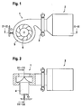
- einen vereinfacht dargestellten Schnitt in der Draufsicht durch einen Gebläsetrakt und einen Teil eines Klimatrakts einer Klimaanlage gemäß dem ersten Ausführungsbeispiel,
- Fig. 2
- einen Schnitt quer durch Fig. 1 entlang der Linie II-II,
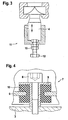
- Fig. 3
- einen Schnitt quer durch Fig. 2 entlang der Linie III-III, und
- Fig. 4
- einen vergrößert dargestellten Schnitt durch eine Entkoppelvorrichtung, und
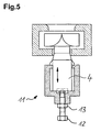
- Fig. 5
- einen Schnitt quer durch Fig. 2 entlang der Linie III-III in einem zweiten erfindungsgemäßen Ausführungsbeispiel.
- Eine Klimaanlage für ein Kraftfahrzeug mit einem Gebläsetrakt 1 und einem Klimatrakt 2, welche durch eine Wand 3 getrennt sind, weist im Gebläsetrakt 1 einen Gebläsemotor 4, der mittels einer Lagerung gelagert ist, und ein Spiralgehäuse 5 mit einem Lüfterrad 6 auf. Hierbei ist der Gebläsemotor 4 über seine Lagerung fest mit dem Spiralgehäuse 5 sowie dem Lüfterrad 6 verbunden. Die Gesamtheit des Gebläsetrakts 1 ist mittels mehrerer Entkoppelvorrichtungen 7, wobei ein Schnitt durch eine derselben in Fig. 4 vergrößert dargestellt ist, mit der Wand 3 verbunden. Der Klimatrakt 2 ist gemäß dem ersten Ausführungsbeispiel starr mit der Wand 3 verbunden.
- Jede Entkoppelvorrichtung 7 umfasst eine Schraube 8, welche fest in die Wand 3 eingeschraubt ist, eine auf die Schraube 8 geschobene Hülse 9 und ein auf die Hülse 9 geschobenes elastisches Element 10, vorliegend einem Elastomer. Das elastische Element 10 hat eine im Wesentlichen zylindrische Gestalt mit einer umlaufenden Nut. Das Spiralgehäuse 5 weist mehrere entsprechend positionierte und entsprechend dem Durchmesser der Nut ausgebildete Bohrungen auf, in welche die jeweilige Entkoppelvorrichtung 7 gesteckt ist.
- Erfindungsgemäß ist zur Einstellung des Spaltmaßes zwischen Spiralgehäuse 5 und Lüfterrad 6 eine Stellvorrichtung 11 vorgesehen, welche im Wesentlichen aus einer fest in das Motorgehäuse geschraubte Schraube 12, die in ein Gewinde im Spiralgehäuse 5 geschraubt und mittels einer Kontermutter 13 gesichert ist. Durch ein Verdrehen der Schraube 12 nach dem Lösen der Kontermutter 13 lässt sich die Längsposition des Lüfterrades 6 im Spiralgehäuse 5 einfach einstellen. Nach dem Einstellen erfolgt die Sicherung mittels der Kontermutter 13.
- In einem zweiten erfindungsgemäßen Ausführungsbeispiel zeigt Fig.5 zur Einstellung des Spaltmaßes zwischen Spiralgehäuse 5 und Lüfterrad 6 eine Stellvorrichtung 11, bei der die Schraube 12 zur Verstellung des Spaltmaßes mit einem stumpfwinkeligen kegelförmigen Ende versehen ist, welches die axiale Verschiebung beim Verdrehen der Schraube auf einen Anschlussbereich des Gebläsemotors 14 überträgt. Gesichert wird die Schraube 12 wieder mittels einer Kontermutter 13.
- Am Motor kann gemäß einem weiteren, nicht in der Zeichnung dargestellten Ausführungsbeispiel ein der Welle des Motors, welche das Lüfterrad trägt, gegenüberliegend angeordneter, höhenverstellbarer Deckel mit einem Gewinde vorgesehen sein, der zur Einstellung des Spaltmaßes dient (Stellvorrichtung) und starr mit einer Wand verbunden ist oder mit derselben verbunden werden kann. Zur Abstützung des Motors gegen auf denselben einwirkende Momente, welche unter Umständen ein Verstellen des eingestellten Spaltmaßes bewirken können, ist seitlich am Motorgehäuse mindestens eine Drehmomentenstütze in Form eines mit einer an der Wand vorgesehenen Schulter zusammenwirkenden Vorsprunges vorgesehen.
- Zur Sicherung des Deckels am Motorgehäuse sind über den Umfang desselben gleichmäßig verteilt zwei Sicherungsschrauben vorgesehen, die den Deckel mit dem Motorgehäuse verspannen und somit sichern. Zur Unterstützung deren Wirkung können im Motorgehäuse Nuten vorgesehen sein, die in Längsrichtung desselben verlaufen und in die die Sicherungsschrauben eingreifen.
- Zur Einstellung des Spaltmaßes sind beliebige andere Stellvorrichtungen möglich, wie zum Beispiel das Vorsehen von Rastöffnungen im bevorzugt zylinderförmig ausgebildeten Motorgehäuse, die mit sich in radialer Richtung angeordneten Verriegelungsbolzen zusammenwirken. Hierbei sind vorzugsweise drei Verriegelungsbolzen gleichmäßig über den Umfang verteilt vorgesehen.
-
- 1
- Gebläsetrakt
- 2
- Klimatrakt
- 3
- Wand
- 4
- Gebläsemotor
- 5
- Spiralgehäuse
- 6
- Lüfterrad
- 7
- Entkoppelvorrichtung
- 8
- Schraube
- 9
- Hülse
- 10
- elastisches Element
- 11
- Stellvorrichtung
- 12
- Schraube
- 13
- Kontermutter
Claims (10)
- Gebläse mit einer entkoppelten Befestigungsvorrichtung, die an einem Strukturteil eines Fahrzeugs oder Gehäuse einer Klimaanlage anordenbar ist, mit einem Gebläsemotor (4), der mittels einer Lagerung gelagert ist, einem Spiralgehäuse (5) mit Lüfterrad (6) wobei das Spiralgehäuse (5) mit Lüfterrad (6) und Gebläsemotor (4) entkoppelt ist und einer Stellvorrichtung (11) zur Einstellung des Spaltmaßes, dadurch gekennzeichnet, dass die Stellvorrichtung (11) zur Einstellung des Spaltmaßes in Längsrichtung der Lüfterraddrehachse ein Gewinde aufweist, welches eine Längsverstellung bewirkt.
- Gebläse nach Anspruch 1, dadurch gekennzeichnet, dass die Entkoppelung am Übergang vom Spiralgehäuse (5) zu einem Klimatrakt (2) der Klimaanlage und/oder an der Befestigung des Spiralgehäuses (5) an einem Strukturteil vorgesehen ist.
- Gebläse nach Anspruch 2, dadurch gekennzeichnet, dass das Strukturteil ein Querträger oder eine Wand (3) ist.
- Gebläse nach einem der vorhergehenden Ansprüche, dadurch gekennzeichnet, dass die Entkoppelung über Schraubverbindungen erfolgt, wobei zwischen Schraube (8) und Spiralgehäuse (5) ein elastisches Element (10) vorgesehen ist.
- Gebläse nach Anspruch 4, dadurch gekennzeichnet, dass zwischen der Schraube (8) und dem elastischen Element (10) eine Hülse (9) vorgesehen ist.
- Gebläse nach Anspruch 1 oder 2, dadurch gekennzeichnet, dass die Entkoppelung über die Weichheit der Verbindung von Spiralgehäuse (5) zu einer Klimaanlage erfolgt.
- Gebläse nach Anspruch 6, dadurch gekennzeichnet, dass die Entkoppelung über eine 2-Komponenten-Verbindung, eine Hart-Weich-Kombination, eine teilweise Filmscharnier-Verbindung, ein Abdichtelement zwischen Spiralgehäuse und Klimaanlage und/oder mittels Zusammenspritzen und/oder über die Montage-Verbindung erfolgt.
- Gebläse nach einem der vorhergehenden Ansprüche, dadurch gekennzeichnet, dass im Spiralgehäuse (5) oder fest mit demselben verbunden ein Gewinde vorgesehen ist, in das eine das Gewinde zur Verfügung stellende Schraube (12) geschraubt ist
- Gebläse nach einem der vorhergehenden Ansprüche, dadurch gekennzeichnet, dass auf das Gewinde eine Kontermutter (13) geschraubt ist.
- Gebläse nach einem der vorhergehenden Ansprüche, dadurch gekennzeichnet, dass eine Stellvorrichtung zur Einstellung der Position quer zur Längsrichtung der Lüfterraddrehachse vorgesehen ist.
Applications Claiming Priority (2)
| Application Number | Priority Date | Filing Date | Title |
|---|---|---|---|
| DE10321394 | 2003-05-12 | ||
| DE10321394 | 2003-05-12 |
Publications (3)
| Publication Number | Publication Date |
|---|---|
| EP1477346A2 EP1477346A2 (de) | 2004-11-17 |
| EP1477346A3 EP1477346A3 (de) | 2005-10-05 |
| EP1477346B1 true EP1477346B1 (de) | 2007-05-02 |
Family
ID=33016363
Family Applications (1)
| Application Number | Title | Priority Date | Filing Date |
|---|---|---|---|
| EP04011266A Expired - Lifetime EP1477346B1 (de) | 2003-05-12 | 2004-05-12 | Entkoppeltes Gebläse |
Country Status (3)
| Country | Link |
|---|---|
| EP (1) | EP1477346B1 (de) |
| AT (1) | ATE361210T1 (de) |
| DE (2) | DE502004003657D1 (de) |
Cited By (1)
| Publication number | Priority date | Publication date | Assignee | Title |
|---|---|---|---|---|
| US20210215173A1 (en) * | 2014-01-03 | 2021-07-15 | Bmc Medical Co., Ltd. | Blower device and respirator including blower device |
Families Citing this family (3)
| Publication number | Priority date | Publication date | Assignee | Title |
|---|---|---|---|---|
| DE102005004450A1 (de) * | 2005-02-01 | 2006-08-03 | Daimlerchrysler Ag | Mittelkonsole eines Kraftfahrzeugs |
| DE102015116350A1 (de) * | 2015-09-28 | 2017-03-30 | Valeo Klimasysteme Gmbh | Befestigungsmodul zur Befestigung eines Gebläsemotors sowie Heizungs-, Lüftungs- und/oder Klimaanlagenmodul |
| US10837461B2 (en) * | 2019-04-10 | 2020-11-17 | Haier Us Appliance Solutions, Inc. | Vibration isolating mounting of fan |
Family Cites Families (3)
| Publication number | Priority date | Publication date | Assignee | Title |
|---|---|---|---|---|
| US4807718A (en) * | 1987-03-18 | 1989-02-28 | Digital Equipment Corporation | Acoustic noise control for fans |
| DE9104643U1 (de) * | 1991-04-16 | 1991-10-10 | Keller Lufttechnik GmbH + Co KG, 7312 Kirchheim | Ventilatoreinheit |
| DE4238895C1 (de) * | 1992-11-19 | 1993-12-16 | Howatherm Klimatech Gmbh | Ventilatoraggregat zum Einbau in einen Luftkanal eines raumlufttechnischen Gerätes |
-
2004
- 2004-05-12 DE DE502004003657T patent/DE502004003657D1/de not_active Expired - Lifetime
- 2004-05-12 EP EP04011266A patent/EP1477346B1/de not_active Expired - Lifetime
- 2004-05-12 AT AT04011266T patent/ATE361210T1/de not_active IP Right Cessation
- 2004-05-12 DE DE200410023931 patent/DE102004023931A1/de not_active Withdrawn
Cited By (2)
| Publication number | Priority date | Publication date | Assignee | Title |
|---|---|---|---|---|
| US20210215173A1 (en) * | 2014-01-03 | 2021-07-15 | Bmc Medical Co., Ltd. | Blower device and respirator including blower device |
| US12247585B2 (en) | 2014-01-03 | 2025-03-11 | Bmc Medical Co., Ltd. | Blower device and respirator including blower device |
Also Published As
| Publication number | Publication date |
|---|---|
| EP1477346A2 (de) | 2004-11-17 |
| ATE361210T1 (de) | 2007-05-15 |
| DE102004023931A1 (de) | 2004-12-30 |
| EP1477346A3 (de) | 2005-10-05 |
| DE502004003657D1 (de) | 2007-06-14 |
Similar Documents
| Publication | Publication Date | Title |
|---|---|---|
| EP1447898B1 (de) | Aussenläufermotor | |
| DE19712228A1 (de) | Befestigungsvorrichtung für einen Gebläsemotor | |
| WO2001099256A1 (de) | Vorrichtung zur schwingungsisolierenden halterung eines elektromotors | |
| EP0986489B1 (de) | Entkopplungsvorrichtung für einen elektromotor | |
| EP2655918B1 (de) | Schwingungsdämpfende aufnahmevorrichtung | |
| DE102015106070A1 (de) | Axialgebläse für ein Kühlgebläsemodul | |
| DE102017003288B4 (de) | Lageranordnung für eine Fahrzeuglenkvorrichtung sowie Fahrzeuglenkvorrichtung, die diese aufweist | |
| EP1477346B1 (de) | Entkoppeltes Gebläse | |
| DE102022001475A1 (de) | Elektromotor mit Lüfterhaube und Sensor | |
| DE10316108B4 (de) | Dichtungselement für eine Kühlmodulanordnung eines Kraftfahrzeuges und Kühlmodulanordnung mit einem solchen Dichtungselement | |
| DE102015212408A1 (de) | Halterung mit mehreren Dämpfungselementen | |
| EP0668650B1 (de) | Anordnung zur schwingungsgedämpften Halterung eines Elektromotors | |
| EP1978259A2 (de) | Schalldämpfer zur Verwendung an einem Kompressor | |
| EP2381112A2 (de) | Axiallüfter | |
| DE102014225016A1 (de) | Einrichtung zum Befestigen eines Bauteils in einem Fahrzeug | |
| EP2060379B1 (de) | Schwingungsentkoppelnder Halter | |
| DE102021205791A1 (de) | Loslageranordnung | |
| EP1913263B1 (de) | Gebläsevorrichtung für ein gargerät | |
| DE3546537C2 (de) | ||
| DE202018105205U1 (de) | Getriebe | |
| DE102007039814B4 (de) | Befestigungsvorrichtung für Gebläsemotor sowie Fahrzeuggebläse | |
| DE102011079617A1 (de) | Schraubverbindung | |
| DE102016207698A1 (de) | Ladeeinrichtung | |
| DE19958261C2 (de) | Axiallüfter | |
| WO2025140808A1 (de) | Elektromotor mit lüfterhaube und ersten winkelsensor |
Legal Events
| Date | Code | Title | Description |
|---|---|---|---|
| PUAI | Public reference made under article 153(3) epc to a published international application that has entered the european phase |
Free format text: ORIGINAL CODE: 0009012 |
|
| AK | Designated contracting states |
Kind code of ref document: A2 Designated state(s): AT BE BG CH CY CZ DE DK EE ES FI FR GB GR HU IE IT LI LU MC NL PL PT RO SE SI SK TR |
|
| AX | Request for extension of the european patent |
Extension state: AL HR LT LV MK |
|
| PUAL | Search report despatched |
Free format text: ORIGINAL CODE: 0009013 |
|
| AK | Designated contracting states |
Kind code of ref document: A3 Designated state(s): AT BE BG CH CY CZ DE DK EE ES FI FR GB GR HU IE IT LI LU MC NL PL PT RO SE SI SK TR |
|
| AX | Request for extension of the european patent |
Extension state: AL HR LT LV MK |
|
| 17P | Request for examination filed |
Effective date: 20060405 |
|
| AKX | Designation fees paid |
Designated state(s): AT BE BG CH CY CZ DE DK EE ES FI FR GB GR HU IE IT LI LU MC NL PL PT RO SE SI SK TR |
|
| GRAP | Despatch of communication of intention to grant a patent |
Free format text: ORIGINAL CODE: EPIDOSNIGR1 |
|
| GRAS | Grant fee paid |
Free format text: ORIGINAL CODE: EPIDOSNIGR3 |
|
| GRAA | (expected) grant |
Free format text: ORIGINAL CODE: 0009210 |
|
| AK | Designated contracting states |
Kind code of ref document: B1 Designated state(s): AT BE BG CH CY CZ DE DK EE ES FI FR GB GR HU IE IT LI LU MC NL PL PT RO SE SI SK TR |
|
| PG25 | Lapsed in a contracting state [announced via postgrant information from national office to epo] |
Ref country code: FI Free format text: LAPSE BECAUSE OF FAILURE TO SUBMIT A TRANSLATION OF THE DESCRIPTION OR TO PAY THE FEE WITHIN THE PRESCRIBED TIME-LIMIT Effective date: 20070502 |
|
| REG | Reference to a national code |
Ref country code: GB Ref legal event code: FG4D Free format text: NOT ENGLISH |
|
| REG | Reference to a national code |
Ref country code: CH Ref legal event code: EP |
|
| REG | Reference to a national code |
Ref country code: IE Ref legal event code: FG4D Free format text: LANGUAGE OF EP DOCUMENT: GERMAN |
|
| REF | Corresponds to: |
Ref document number: 502004003657 Country of ref document: DE Date of ref document: 20070614 Kind code of ref document: P |
|
| GBT | Gb: translation of ep patent filed (gb section 77(6)(a)/1977) |
Effective date: 20070705 |
|
| PG25 | Lapsed in a contracting state [announced via postgrant information from national office to epo] |
Ref country code: SE Free format text: LAPSE BECAUSE OF FAILURE TO SUBMIT A TRANSLATION OF THE DESCRIPTION OR TO PAY THE FEE WITHIN THE PRESCRIBED TIME-LIMIT Effective date: 20070802 |
|
| PG25 | Lapsed in a contracting state [announced via postgrant information from national office to epo] |
Ref country code: ES Free format text: LAPSE BECAUSE OF FAILURE TO SUBMIT A TRANSLATION OF THE DESCRIPTION OR TO PAY THE FEE WITHIN THE PRESCRIBED TIME-LIMIT Effective date: 20070813 |
|
| ET | Fr: translation filed | ||
| NLV1 | Nl: lapsed or annulled due to failure to fulfill the requirements of art. 29p and 29m of the patents act | ||
| PG25 | Lapsed in a contracting state [announced via postgrant information from national office to epo] |
Ref country code: PL Free format text: LAPSE BECAUSE OF FAILURE TO SUBMIT A TRANSLATION OF THE DESCRIPTION OR TO PAY THE FEE WITHIN THE PRESCRIBED TIME-LIMIT Effective date: 20070502 |
|
| REG | Reference to a national code |
Ref country code: IE Ref legal event code: FD4D |
|
| BERE | Be: lapsed |
Owner name: BEHR G.M.B.H. & CO. KG Effective date: 20070531 |
|
| PG25 | Lapsed in a contracting state [announced via postgrant information from national office to epo] |
Ref country code: IE Free format text: LAPSE BECAUSE OF FAILURE TO SUBMIT A TRANSLATION OF THE DESCRIPTION OR TO PAY THE FEE WITHIN THE PRESCRIBED TIME-LIMIT Effective date: 20070502 Ref country code: NL Free format text: LAPSE BECAUSE OF FAILURE TO SUBMIT A TRANSLATION OF THE DESCRIPTION OR TO PAY THE FEE WITHIN THE PRESCRIBED TIME-LIMIT Effective date: 20070502 Ref country code: BG Free format text: LAPSE BECAUSE OF FAILURE TO SUBMIT A TRANSLATION OF THE DESCRIPTION OR TO PAY THE FEE WITHIN THE PRESCRIBED TIME-LIMIT Effective date: 20070802 Ref country code: SI Free format text: LAPSE BECAUSE OF FAILURE TO SUBMIT A TRANSLATION OF THE DESCRIPTION OR TO PAY THE FEE WITHIN THE PRESCRIBED TIME-LIMIT Effective date: 20070502 Ref country code: PT Free format text: LAPSE BECAUSE OF FAILURE TO SUBMIT A TRANSLATION OF THE DESCRIPTION OR TO PAY THE FEE WITHIN THE PRESCRIBED TIME-LIMIT Effective date: 20071002 Ref country code: DK Free format text: LAPSE BECAUSE OF FAILURE TO SUBMIT A TRANSLATION OF THE DESCRIPTION OR TO PAY THE FEE WITHIN THE PRESCRIBED TIME-LIMIT Effective date: 20070502 Ref country code: CZ Free format text: LAPSE BECAUSE OF FAILURE TO SUBMIT A TRANSLATION OF THE DESCRIPTION OR TO PAY THE FEE WITHIN THE PRESCRIBED TIME-LIMIT Effective date: 20070502 Ref country code: MC Free format text: LAPSE BECAUSE OF NON-PAYMENT OF DUE FEES Effective date: 20070531 |
|
| PG25 | Lapsed in a contracting state [announced via postgrant information from national office to epo] |
Ref country code: SK Free format text: LAPSE BECAUSE OF FAILURE TO SUBMIT A TRANSLATION OF THE DESCRIPTION OR TO PAY THE FEE WITHIN THE PRESCRIBED TIME-LIMIT Effective date: 20070502 |
|
| PLBE | No opposition filed within time limit |
Free format text: ORIGINAL CODE: 0009261 |
|
| STAA | Information on the status of an ep patent application or granted ep patent |
Free format text: STATUS: NO OPPOSITION FILED WITHIN TIME LIMIT |
|
| PG25 | Lapsed in a contracting state [announced via postgrant information from national office to epo] |
Ref country code: BE Free format text: LAPSE BECAUSE OF NON-PAYMENT OF DUE FEES Effective date: 20070531 |
|
| 26N | No opposition filed |
Effective date: 20080205 |
|
| PG25 | Lapsed in a contracting state [announced via postgrant information from national office to epo] |
Ref country code: GR Free format text: LAPSE BECAUSE OF FAILURE TO SUBMIT A TRANSLATION OF THE DESCRIPTION OR TO PAY THE FEE WITHIN THE PRESCRIBED TIME-LIMIT Effective date: 20070803 Ref country code: IT Free format text: LAPSE BECAUSE OF FAILURE TO SUBMIT A TRANSLATION OF THE DESCRIPTION OR TO PAY THE FEE WITHIN THE PRESCRIBED TIME-LIMIT Effective date: 20070502 |
|
| PG25 | Lapsed in a contracting state [announced via postgrant information from national office to epo] |
Ref country code: RO Free format text: LAPSE BECAUSE OF FAILURE TO SUBMIT A TRANSLATION OF THE DESCRIPTION OR TO PAY THE FEE WITHIN THE PRESCRIBED TIME-LIMIT Effective date: 20070502 |
|
| PG25 | Lapsed in a contracting state [announced via postgrant information from national office to epo] |
Ref country code: AT Free format text: LAPSE BECAUSE OF NON-PAYMENT OF DUE FEES Effective date: 20070512 |
|
| PGFP | Annual fee paid to national office [announced via postgrant information from national office to epo] |
Ref country code: GB Payment date: 20080520 Year of fee payment: 5 |
|
| REG | Reference to a national code |
Ref country code: CH Ref legal event code: PL |
|
| PG25 | Lapsed in a contracting state [announced via postgrant information from national office to epo] |
Ref country code: EE Free format text: LAPSE BECAUSE OF FAILURE TO SUBMIT A TRANSLATION OF THE DESCRIPTION OR TO PAY THE FEE WITHIN THE PRESCRIBED TIME-LIMIT Effective date: 20070502 Ref country code: CH Free format text: LAPSE BECAUSE OF NON-PAYMENT OF DUE FEES Effective date: 20080531 Ref country code: LI Free format text: LAPSE BECAUSE OF NON-PAYMENT OF DUE FEES Effective date: 20080531 |
|
| PG25 | Lapsed in a contracting state [announced via postgrant information from national office to epo] |
Ref country code: CY Free format text: LAPSE BECAUSE OF FAILURE TO SUBMIT A TRANSLATION OF THE DESCRIPTION OR TO PAY THE FEE WITHIN THE PRESCRIBED TIME-LIMIT Effective date: 20070502 |
|
| PG25 | Lapsed in a contracting state [announced via postgrant information from national office to epo] |
Ref country code: LU Free format text: LAPSE BECAUSE OF NON-PAYMENT OF DUE FEES Effective date: 20070512 |
|
| PG25 | Lapsed in a contracting state [announced via postgrant information from national office to epo] |
Ref country code: HU Free format text: LAPSE BECAUSE OF FAILURE TO SUBMIT A TRANSLATION OF THE DESCRIPTION OR TO PAY THE FEE WITHIN THE PRESCRIBED TIME-LIMIT Effective date: 20071103 Ref country code: TR Free format text: LAPSE BECAUSE OF FAILURE TO SUBMIT A TRANSLATION OF THE DESCRIPTION OR TO PAY THE FEE WITHIN THE PRESCRIBED TIME-LIMIT Effective date: 20070502 |
|
| GBPC | Gb: european patent ceased through non-payment of renewal fee |
Effective date: 20090512 |
|
| PG25 | Lapsed in a contracting state [announced via postgrant information from national office to epo] |
Ref country code: GB Free format text: LAPSE BECAUSE OF NON-PAYMENT OF DUE FEES Effective date: 20090512 |
|
| PGFP | Annual fee paid to national office [announced via postgrant information from national office to epo] |
Ref country code: FR Payment date: 20100617 Year of fee payment: 7 |
|
| REG | Reference to a national code |
Ref country code: FR Ref legal event code: ST Effective date: 20120131 |
|
| PG25 | Lapsed in a contracting state [announced via postgrant information from national office to epo] |
Ref country code: FR Free format text: LAPSE BECAUSE OF NON-PAYMENT OF DUE FEES Effective date: 20110531 |
|
| PGFP | Annual fee paid to national office [announced via postgrant information from national office to epo] |
Ref country code: DE Payment date: 20120625 Year of fee payment: 9 |
|
| PG25 | Lapsed in a contracting state [announced via postgrant information from national office to epo] |
Ref country code: DE Free format text: LAPSE BECAUSE OF NON-PAYMENT OF DUE FEES Effective date: 20131203 |
|
| REG | Reference to a national code |
Ref country code: DE Ref legal event code: R119 Ref document number: 502004003657 Country of ref document: DE Effective date: 20131203 |