EP1477402B1 - Vorrichtung zur Steuerung der Bewegungen eines Schiffsrumpfes - Google Patents
Vorrichtung zur Steuerung der Bewegungen eines Schiffsrumpfes Download PDFInfo
- Publication number
- EP1477402B1 EP1477402B1 EP20030076486 EP03076486A EP1477402B1 EP 1477402 B1 EP1477402 B1 EP 1477402B1 EP 20030076486 EP20030076486 EP 20030076486 EP 03076486 A EP03076486 A EP 03076486A EP 1477402 B1 EP1477402 B1 EP 1477402B1
- Authority
- EP
- European Patent Office
- Prior art keywords
- hull
- fin
- interceptor element
- interceptor
- arrangement according
- Prior art date
- Legal status (The legal status is an assumption and is not a legal conclusion. Google has not performed a legal analysis and makes no representation as to the accuracy of the status listed.)
- Expired - Lifetime
Links
Images


Classifications
-
- B—PERFORMING OPERATIONS; TRANSPORTING
- B63—SHIPS OR OTHER WATERBORNE VESSELS; RELATED EQUIPMENT
- B63H—MARINE PROPULSION OR STEERING
- B63H25/00—Steering; Slowing-down otherwise than by use of propulsive elements; Dynamic anchoring, i.e. positioning vessels by means of main or auxiliary propulsive elements
- B63H25/06—Steering by rudders
- B63H25/38—Rudders
- B63H25/382—Rudders movable otherwise than for steering purposes; Changing geometry
-
- B—PERFORMING OPERATIONS; TRANSPORTING
- B63—SHIPS OR OTHER WATERBORNE VESSELS; RELATED EQUIPMENT
- B63H—MARINE PROPULSION OR STEERING
- B63H25/00—Steering; Slowing-down otherwise than by use of propulsive elements; Dynamic anchoring, i.e. positioning vessels by means of main or auxiliary propulsive elements
- B63H25/06—Steering by rudders
- B63H25/38—Rudders
- B63H25/381—Rudders with flaps
-
- B—PERFORMING OPERATIONS; TRANSPORTING
- B63—SHIPS OR OTHER WATERBORNE VESSELS; RELATED EQUIPMENT
- B63H—MARINE PROPULSION OR STEERING
- B63H25/00—Steering; Slowing-down otherwise than by use of propulsive elements; Dynamic anchoring, i.e. positioning vessels by means of main or auxiliary propulsive elements
- B63H25/44—Steering or slowing-down by extensible flaps or the like
Definitions
- the present invention relates to an arrangement for controlling the motion of a vessel hull comprising: a tapered fin defining a span and having a swept leading edge, a generally vertical trailing edge and being adapted for mounting on said hull; and an interceptor element arranged at said trailing edge and being adapted to be deployed in a direction which is generally perpendicular to the longitudinal extension of the fin in order to generate forces for controlling said hull.
- the invention is intended in particular for manouvering hulls of high-speed vessels of the type which are waterjet-propelled, that is to say vessels with a water-free stern during operation, or other types of high-speed vessels such as smaller high-speed boats. It is also possible to use the invention for vessels or boats which are driven in other ways than by water-jet units.
- the document WO 99/44885 teaches an arrangement for control of the course of a high-speed vessel hull.
- the arrangement comprises flap members, so-called interceptors, which are arranged on the stem of the hull so as to be displaced at an angle in relation to the water flow. In this manner, force components will be generated which bring about a change in the course of the vessel hull.
- steering of waterjet-driven vessels is effected by controlling the direction of the water jet using course-changing means in the form of rotatable nozzles and/or rotatable shutter-like or scoop-like members.
- course-changing means in the form of rotatable nozzles and/or rotatable shutter-like or scoop-like members.
- the dimensions of these course-changing means must be adapted so as to provide sufficent course-changing effect both at low speeds, such as when the vessel is within a harbour area, and when travelling at higher speed.
- interceptors such as shown in WO 99/44885
- hulls with wetted sides The general principles for the operation of such interceptors are described in the document US 6006689 , and rely on the fact that the interceptor can be displaced between different positions with respect to the hull. In this manner, the water pressure acting on the side of the hull can be increased in order to change the course of the vessel.
- a further interceptor device is shown in the document WO 99/57007 and comprises an adjustable interceptor which is arranged on a hydrofoil wing.
- the interceptor defines a protrusion in relation to a surface on the wing so as to increase the local pressure acting on said surface when the wing is travelling through water.
- the document EP-A-0431678 teaches an arrangement for controlling the motion of a vessel hull.
- the arrangement comprises a tapered fin which is arranged on the vessel hull.
- the arrange ment also comprises a steering element which is arranged at the trailing edge of the tapered fin.
- the document US-A-6467422 teaches a hydrofoil device which to be used as a hydrofoil wing.
- the device provides a certain deployment in order to steer the vessel in which it is mounted.
- One object of the present invention is to provide an improved arrangement for steering of a high-speed water vessel hull.
- interceptor element is adapted for providing a deployment so that the ratio between its deployment distribution and the chord length distribution of said fin along said span is essentially constant.
- the invention provides efficient steering of a vessel hull, with an arrangement which is compact and has a less complex design than previously known steering arrangements for vessels. Furthermore, the interceptor element can be mounted and operated in a manner so that a relatively small power device can be used, which also saves space and cost. Furthermore, the invention provides a deployment of the interceptor which in turn results in a high lift-drag ratio for the steering arrangement while providing good cavitation characteristics of the fin.
- high-speed vessel or “high-speed ship” generally relates to boats and ships having a speed exceeding approximatly 30 knots, which is normal as regards waterjet-driven ships.
- the principles of the invention is not limited to any particular speed range or ship type.
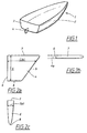
- FIG. 1 shows a vessel such as a ship 1, which in a known manner comprises a hull 2.
- a stem 3 is formed in the aft section of the hull 2.
- a fin 4 is arranged in a manner so that it is generally ailgned with the stem 3, i.e. the trailing edge of the fin 4 is generally aligned with the lowermost part of the stern 3.
- the fin 4 is arranged in a fixed manner, for increasing directional stability of the hull in the lateral direction, i.e. for obtaining a sufficient degree of stability when the hull 2 travels through water.
- the fin 4 is designed with a tapered shape, with a swept leading edge 5 and a generally vertical trailing edge 6.
- the height of the trailing edge 6 defines the span S of the fin 4.
- the distance between the leading edge 5 and the trailing edge 6 corresponds to the so-called chord length C of the fin 4.
- the chord length C is a function of the span (i.e. the spanwise coordinate s) of the fin 4, and consequently defines the so-called chord length distribution C(s) of the fin 4.
- the fin 4 comprises a root 7 which is intended to be mounted on the bottom of the hull (see Fig. 1) and a tip 8. In a manner which is known, the root 7 may be attached to the bottom for example by means of bolts or by welding.
- Fig. 2b which is a cross-sectional view of the fin 4
- the fin 4 has a generally tapered or trapezoidal shape, with a leading edge 5 which is rounded and a trailing edge 6 which is generally flat.
- the cross-section of the fin 4 can be wedge-shaped, half elliptical or the like.
- the invention is not limited to any specific cross-sectional shape.
- the shape of the fin is chosen so as to be suitable for ships having a maximum speed of approximately 30 knots or more.
- a basic principle behind the fin 4 is that it is designed in a manner so as to generate a zone 4a which is filled, either naturally or by force (for example by means of an air pump), with air when the fin 4 travels through water.
- a zone 4a which is filled, either naturally or by force (for example by means of an air pump), with air when the fin 4 travels through water.
- Such a design of a fin is referred to as a base-ventilated fin.
- the trailing edge 6 has a shape which is tapered in a direction from the root 7 to the tip 8. More precisely, the trailing edge 6 can be said to define a width T which varies along the span. In this manner, a thickness distribution T(s) of the fin 4 can be defined.
- chord length distribution C(s) of the fin 4 is a generally linear function of the spanwise coordinate s.
- thickness distribution T(s) is a generally linear function of the spanwise coordinate s.
- FIGs. 3a-3d the general principles behind the invention are explained with reference to a side view, a cross-sectional view, a rear view and a perspective view, respectively, of a fin 9 according to a preferred embodiment of the invention. It should be noted that Figs. 3a-3d are simplified and that a more detailed explanation of an embodiment of the invention will be described below with reference to Figs. 4a, 4b and 5.
- the present invention constitutes an arrangement which is primarily intended for steering a ship.
- the fin 9 is intended not only for providing course stability.
- the fin 9 has a generally tapered or trapezoidal shape and is designed with a leading edge 10 and a trailing edge 11.
- the leading edge 10 is swept, i.e. it has a shape which is generally inclined with respect to an imaginary vertical line extending along the fin.
- the so-called sweep angle is defined as the angle between said vertical line and the leading edge 10.
- an interceptor element 12 is arranged Immediately rear of the trailing edge 11, an interceptor element 12 is arranged. It is a general principle behind the present invention that the interceptor element 12 has outer dimensions which correspond essentially to the shape of the trailing edge 11, and also that the interceptor element 12 is preferably displaced along a plane which is generally perpendicular to the longitudinal direction of the fin 9. This means that the deployment of the interceptor element 12 is in a direction perpendicular to the direction of travel of the ship on which the fin 9 is mounted. In this manner, forces are generated as a result of an increase in pressure which is generated on the fin 9, in order to steer the ship.
- the fin 9 is shaped with a root 13 and a tip 14.
- the root 13 is intended to be mounted on the bottom of a hull 15 (which is indicated by means of broken lines in Fig. 3a). This is preferably made in a manner so that the interceptor element 12 is aligned with the stern 16 of the hull 15. Furthermore, and as shown in Fig. 3a, the interceptor element 12 preferably extends along the trailing edge 11 of the fin 9 between the root 13 and the tip 14.
- the interceptor element 12 can be displaced from an initial position immediately behind (and aligned with) the trailing edge 11 of the fin 9 to either one of two end positions, as shown with an arrow. These end positions are indicated in Fig. 3b with brokes lines.
- Fig. 3c which is a rear view showing the displacement or deployment of the interceptor element 12. More precisely, Fig. 3c indicates that the interceptor element 12 has a tapered shape which is oriented along an imagined axis of symmetry 17. In the initial position of the interceptor element 12, the axis 17 of symmetry extends in a vertical manner as shown in Fig. 3c. Furthermore, in a manner which corresponds to Fig.
- the interceptor element 12 (and the trailing edge 11) is shaped with a thickness distribution T(s) which is a function of the span S of the fin 9.
- the thickness varies from a maximum value t root closest to the root, to a minimum value t tip at the tip of the fin 9.
- the fin 9 according to the invention has a chord length distribution C(s) as shown in Fig. 3a.
- the trailing edge 11 is generally flat (i.e. as regarded along a plane which is generally perpendicular to the longitudinal extension of the fin and the ship). As mentioned above, this is referred to as a base-ventilated fin shape.
- the deployment h of the interceptor element 12 depends on the lateral position of the interceptor element 12 in relation to the trailing edge 11 of the fin 9. In this manner, the deployment distribution h(s) of the fin 9 as a function of the spanwise coordinate s is defined.
- steering of a ship's hull 15 is accomplished by means of a suitable degree of deployment of the interceptor element 12 in relation to the fin 9.
- L/D lift-drag ratio
- the lift of the steering arrangement corresponds to the lateral force being obtained during steering due to the deployment of the interceptor element 12
- the drag of the steering arrangement corresponds to the friction force resulting from the movement of the fin 9 through water and the pressure acting on the interceptor when it is deployed.
- the interceptor element 12 is arranged so that the ratio between the degree of deployment of the interceptor element 12 (i.e. in relation to the fin 9) and the distance between the leading edge 10 and the trailing edge 11 is substantially constant along the fin 9, i.e. at every point along the span of the fin 9.
- the invention is arranged so that the deployment of the interceptor element 12 is carried out in the form of a pivoting movement about an imaginary pivoting point 18 which is positioned a certain distance below the interceptor element 12. This is indicated in Fig. 3c, which shows the deployment of the interceptor element from its initial position to either one of its two end positions.
- Fig. 4a is a perspective view of an arrangement according to the invention.
- the interceptor element 12 is mounted at the stern 16 of the hull 15 (shown by means of broken lines) by means of a housing 19.
- the housing 19 is mounted at a lower part of the stern 16 and is designed with an interior space in which an upper portion of the interceptor element 12 is accommodated.
- the interceptor element 12 is preferably formed as an elongated element which is journalled for sideways deployment by means of three bearing devices 20, 21, 22, which are mounted in the interceptor element 12 as will be explained in greater detail below.
- the upper part of the interceptor element 12 is connected to a first end part of a first link arm 23 which is pivotably arranged about a drive axis 24.
- a power device (not shown in Fig. 4) is arranged on the inside of the hull 15 in order to cause a rotating motion of the drive axis 24 and, as a consequence, a rotating motion of the first link arm 23 also, when there is a desire to steer the hull 15 in either direction.
- the other end part of the first link arm 23 is connected to a first end part of a second link arm 25, which is pivotably arranged about a further pivot point 26 in the housing 19.
- the other end part of the second link arm 25 is connected to the interceptor element 12, preferably at a connection point 27 located at approximately half the length of the interceptor element 12.
- the connections between the two link arms 23, 25 and the interceptor element 12 are of the type which are slidable, so that the deployment of the interceptor element 12 can be provided by rotating the drive axis 24.
- FIG. 4a the interceptor element 12 is shown in a position in which it is fully deployed.
- Fig. 4b shows the arrangement according to the invention in a perspective view from generally the opposite direction as compared with Fig. 4a and also showing the interceptor element 12 in a fully deployed position.
- the housing 19 is connected with a elongated element 28 having generally the same shape as the trailing edge 11 (see Fig. 3a) of the fin 9. Consequently, this elongated element 28 forms an extension of the trailing edge 11.
- the housing 19 and the elongated element 28 are attached to each other so as to form a single unit. Also, in Fig.
- the drive axis 24 is shown as regarded from inside the hull 15.
- the drive axis 24 ends with a connection 29 which is intended to be coupled to an actuating device 30 which is indicated in a schematical manner with broken lines.
- the actuating device 30 is preferably in the form of an electric servo intended for providing rotation of the drive axis 24 and consequently for providing the desired degree of steering. It is an advantage of the present invention that the actuating device 30 can be made with a relatively low power requirement in order to provide the steering operation.
- Fig. 5 the arrangement according to the invention is shown in a condition which essentially corresponds to Fig. 4a but in which the interceptor element 12 is in its initial position, i.e. without providing any steering of the hull.
- the second link arm 25 is positioned in a generally vertical direction.
- the interceptor element 12 is not pivoted about any rotation axis, for example toward the lower part of the of the fin 9. Instead, the interceptor element 12 is journalled in a manner so that it can be displaced in a lateral direction with the aid of the three bearing devices 20, 21, 22. Furthermore, in order to aid the lateral displacement of the interceptor element 12, it is generally shaped as a "T" (see Fig. 4a) with a generally vertical component and a generally horizontal component, of which the horizontal component is journalled on the two upper bearing devices 21, 22 carried by the interceptor element 12. Also, the housing 19 is preferably formed with a generally horizontal groove or recess (not shown) so as to define a track in which the horizontal component may be displaced.
- the lower end portion of the interceptor element 12 can also be displaced in a lateral direction, more precisely by being guided by means of a streamlined bulb extension 31 a, i.e. an extension of a bulb 31 which is formed along the tip 14 of the fin 9. Said bulb 31 is shown in a schematical manner (with broken lines) in Fig. 4b. More precisely, the interceptor element 12 is guided during said displacement along a track or slot which is defined in the bulb extension 31 a in a manner so that the displacement is facilitated by the lower bearing device 20 in the interceptor element 12.
- a streamlined bulb extension 31 a i.e. an extension of a bulb 31 which is formed along the tip 14 of the fin 9.
- Said bulb 31 is shown in a schematical manner (with broken lines) in Fig. 4b. More precisely, the interceptor element 12 is guided during said displacement along a track or slot which is defined in the bulb extension 31 a in a manner so that the displacement is facilitated by the lower bearing device 20 in the interceptor element 12.
- the bulb extension 31 a is attached to the lower end portion of the elongated element 28.
- the lower end portion of the interceptor element 12 is not pivotable about any fixed point. Instead, the deployment of the interceptor element 12 is carried out in a manner so that its imaginary axis of symmetry 17 (see Fig. 3c) is pivoting about an imaginary pivoting point 18 which is positioned below said interceptor element 12.
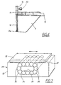
- Fig. 6 shows a side view of an arrangement according to the invention as mounted on a vessel hull 15.
- the fin 9 is mounted on the bottom of the hull 15 and the interceptor element 12 is arranged as an extension of the stern 16 of the hull 15.
- the housing 19 is mounted on the lower part of the stern 16 so that the interceptor element 12 extends into said housing 19.
- the lower end portion of the interceptor element 12 is guided during its deployment in the track defined by the bulb extension 31 a.
- the electric servo 30 is mounted on the inside of the hull 15, in a manner so that it is connected to the above-mentioned first link arm (not shown in Fig. 6) as explained above.
- a bearing device 20 of the type as mentioned above is shown in detail in Fig. 7, which shows the basic principle involving two a first object 32 which is journalled in relation to a bearing device 20. It should be noted that the bearing device 20 is not limited to being used in the field of interceptor elements, but can be used in any application in which there is a desire to provide a bearing for an object which is to be displaced in a sideways direction.
- the bearing device 20 comprises a housing 33 which is designed with a cavity 34.
- the cavity 34 is formed generally as a closed shape, i.e. a loop, and preferably as a rectangle or an oval which has a centrepiece 35 which is fixedly connected to the housing 33.
- a number of rolls 36 are placed in the generally oval space which is formed in the housing 33.
- the housing 33 is formed with an upper surface 37 on which the object 32 is intended to be journalled. The distance between the centrepiece 35 and the upper surface 37 is slighly less than the diameter of each of the rolls 36. This means that the object 32 will be carried on a surface being constituted by a number of rolling rolls 36.
- the principle of the bearing 20 as shown in Fig. 7 can be used for supporting the interceptor element 12 as shown in Figs. 4a, 4b, 5 and 7. This means that the interceptor element 12 can be deployed between its initial position and either one of its end positions with relatively low friction. This also contributes to the fact that only a relatively small actuating device, such as the above-mentioned electric servo 30, can be used for providing the steering of the hull.
- the fin 9 according to the invention is primarily intended for steering of a ship hull, it should be noted that the principles of the invention can be used in other ways, depending on in what manner the fin 9 is mounted on a ship.
- the fin can be used for trimming purposes (if it is inclined by approximately 45° with respect to the vertical direction as shown in Figs. 3a-3d), and can also be used as a hydrofoil.
- the fin according to the invention can be used for controlling roll, heave and pitch movements of a hull. Consequently, the fin according to the invention can be used in a general manner for controlling the motion of a vessel hull.
- the invention is not limited to deployment of the interceptor element along a plane which is perpendicular to the direction of the travel of the vessel, as discussed above.
- the interceptor element can be arranged so as to be deployed for example along a conical surface, in order to provide the necessary forces for controlling a vessel.
Landscapes
- Chemical & Material Sciences (AREA)
- Engineering & Computer Science (AREA)
- Combustion & Propulsion (AREA)
- Mechanical Engineering (AREA)
- Ocean & Marine Engineering (AREA)
- Vibration Prevention Devices (AREA)
- Prevention Of Electric Corrosion (AREA)
Claims (8)
- Anordnung zur Steuerung der Bewegungen eines Fahrzeugrumpfes (15) mit:einer sich verjüngenden Flosse (9), die eine Spannweite definiert und eine gekippte vordere Kante (10), eine im Allgemeinen vertikale hintere Kante (11) hat und so eingerichtet ist, um sie an dem Rumpf (15) zu montieren; undeinem Abfangelement (12), das an der hinteren Kante (11) angeordnet und so eingerichtet ist, dass es in einer Richtung eingesetzt wird, die im Allgemeinen rechtwinklig zur Längsausdehnung der Flosse (9) liegt, um Kräfte zur Steuerung des Rumpfes (15) zu erzeugen,dadurch gekennzeichnet, dass
das Abfangelement (12) eingerichtet ist, um einen Einsatz so bereitzustellen, dass das Verhältnis (h(s)/C(s)) zwischen der Einsatzverteilung und der Sehnenlängenverteilung von der Flosse (9) entlang der Spannweite im Wesentlichen konstant ist, und
dass das Abfangelement (12) entlang einer imaginären Symmetrieachse (17) und so angeordnet ist, um in einer Weise eingesetzt zu werden, so dass die Achse (17) um einen imaginären Drehpunkt (18) gedreht wird, der unter dem Abfangelement (12) positioniert ist. - Anordnung nach Anspruch 1,
dadurch gekennzeichnet, dass
das Abfangelement (12) in einem Gehäuse (19) untergebracht ist, das an dem Rumpf (15) befestigt ist, wobei das Abfangelement (12) durch eine Betätigungsvorrichtung (30) bewegbar ist, die mit dem Abfangelement (12) über einen drehbaren Verbindungsarm (23) verbunden ist. - Anordnung nach Anspruch 3,
dadurch gekennzeichnet, dass
der drehbare Verbindungsarm (23) einen ersten Endabschnitt, der mit dem Abfangelement (12) verbunden ist, und einen zweiten Endabschnitt hat, der mit einem weiteren Verbindungsarm (25) verbunden ist, der in dem Gehäuse (19) drehbar angeordnet ist, wobei der weitere Verbindungsarm (25) einen Endabschnitt hat, der mit dem Abfangelement (12) verbunden ist. - Anordnung nach einem der vorhergehenden Ansprüche,
dadurch gekennzeichnet, dass
das Abfangelement (12) einen oberen Endteil und einen unteren Endteil definiert, wobei die Endteile für eine Verschiebung des Abfangelements (12) entlang einer Ebene drehbar gelagert sind, die im Allgemeinen rechtwinklig zur Bewegungsrichtung des Rumpfes (15) liegt. - Anordnung nach Anspruch 4,
dadurch gekennzeichnet, dass
der obere Endteil wenigstens eine Lagervorrichtung (21, 22) trägt, die sich mit dem Gehäuse (19) in Kontakt befindet, um eine Lagerfläche zu definieren, und der untere Endteil wenigstens eine Lagervorrichtung (20), die sich mit einer birnenartigen Erweiterung (31a) in Kontakt befindet, die eine weitere Lagerfläche definiert, und eine Laufbahn trägt, entlang der der untere Endteil beim Einsatz gelagert wird. - Anordnung nach Anspruch 4 oder 5,
dadurch gekennzeichnet, dass
sich der obere Endteil des Abfangelements (12) in das Gehäuse (19) über dem Boden des Rumpfes (15) erstreckt. - Anordnung nach einem der Ansprüche 2 bis 6,
dadurch gekennzeichnet, dass
die Betätigungsvorrichtung (30) mit dem drehbaren Verbindungsarm (23) über eine Rotationsachse (24) verbunden ist, die sich durch ein Heck (16) des Rumpfes (15) erstreckt. - Wasserfahrzeug mit einer Anordnung entsprechend einem der vorhergehenden Ansprüche.
Priority Applications (1)
| Application Number | Priority Date | Filing Date | Title |
|---|---|---|---|
| EP20030076486 EP1477402B1 (de) | 2003-05-16 | 2003-05-16 | Vorrichtung zur Steuerung der Bewegungen eines Schiffsrumpfes |
Applications Claiming Priority (1)
| Application Number | Priority Date | Filing Date | Title |
|---|---|---|---|
| EP20030076486 EP1477402B1 (de) | 2003-05-16 | 2003-05-16 | Vorrichtung zur Steuerung der Bewegungen eines Schiffsrumpfes |
Publications (2)
| Publication Number | Publication Date |
|---|---|
| EP1477402A1 EP1477402A1 (de) | 2004-11-17 |
| EP1477402B1 true EP1477402B1 (de) | 2008-01-09 |
Family
ID=33016943
Family Applications (1)
| Application Number | Title | Priority Date | Filing Date |
|---|---|---|---|
| EP20030076486 Expired - Lifetime EP1477402B1 (de) | 2003-05-16 | 2003-05-16 | Vorrichtung zur Steuerung der Bewegungen eines Schiffsrumpfes |
Country Status (1)
| Country | Link |
|---|---|
| EP (1) | EP1477402B1 (de) |
Families Citing this family (5)
| Publication number | Priority date | Publication date | Assignee | Title |
|---|---|---|---|---|
| CN102015437B (zh) * | 2008-03-12 | 2013-10-09 | 汉弗莱有限责任公司 | 用于船舶的航行平衡和侧倾的动态控制的配置 |
| US11372411B1 (en) | 2019-08-08 | 2022-06-28 | Brunswick Corporation | Marine steering system and method |
| US12110088B1 (en) | 2022-07-20 | 2024-10-08 | Brunswick Corporation | Marine propulsion system and method with rear and lateral marine drives |
| US12258115B2 (en) | 2022-07-20 | 2025-03-25 | Brunswick Corporation | Marine propulsion system and joystick control method |
| US12134454B1 (en) | 2022-07-20 | 2024-11-05 | Brunswick Corporation | Marine propulsion system and method with single rear drive and lateral marine drive |
Family Cites Families (6)
| Publication number | Priority date | Publication date | Assignee | Title |
|---|---|---|---|---|
| JPS60143226A (ja) * | 1983-12-29 | 1985-07-29 | Hiromi Muto | ロ−ラ受け |
| JPS624922A (ja) * | 1985-07-01 | 1987-01-10 | Nippon Thompson Co Ltd | 直線運動用転がり軸受の方向転換路 |
| IT1280348B1 (it) * | 1989-12-06 | 1998-01-15 | Gian Franco Boretti | Carena per imbarcazioni a vela veloci |
| SE513731C2 (sv) | 1998-03-02 | 2000-10-30 | Me Srl | Arrangemang och förfarande för dynamisk kontroll av rörelser och kurs hos ett snabbgående fartygsskrov |
| US6006689A (en) | 1998-04-28 | 1999-12-28 | Profjord Ab | Arrangement for dynamic control of running trim and list of a boat |
| US6467422B1 (en) * | 1998-05-06 | 2002-10-22 | Elms Austrialia Pty Ltd. | Hydrofoil device |
-
2003
- 2003-05-16 EP EP20030076486 patent/EP1477402B1/de not_active Expired - Lifetime
Also Published As
| Publication number | Publication date |
|---|---|
| EP1477402A1 (de) | 2004-11-17 |
Similar Documents
| Publication | Publication Date | Title |
|---|---|---|
| US5163377A (en) | Sailing yacht | |
| CN101484353B (zh) | 具有船首控制表面的船 | |
| US5653189A (en) | Hydrofoil craft | |
| US7198000B2 (en) | Shock limited hydrofoil system | |
| RU2150401C1 (ru) | Глиссер | |
| EP1873051A1 (de) | Schiff | |
| US6578506B2 (en) | Aft hung hydrofoil for reduction of water resistance of partially immersed sailing vessels | |
| CN1102521C (zh) | 高速舵 | |
| US6805068B1 (en) | Hydrofoil system for lifting a boat partially out of water an amount sufficient to reduce drag | |
| US20050215132A1 (en) | Line design and propulsion system for a directionally stable, seagoing boat with rudder propeller drive system | |
| US20240278874A1 (en) | Foldable hydrofoil for boats | |
| EP4126652B1 (de) | Schiff mit am heck angebrachter folie zur verringerung des wellenwiderstandes | |
| EP1472133B1 (de) | Wassefahrzeug | |
| EP1477402B1 (de) | Vorrichtung zur Steuerung der Bewegungen eines Schiffsrumpfes | |
| AU2003207004A1 (en) | Watercraft | |
| US8607724B2 (en) | Rudder assembly with a deflectable trailing tab | |
| US5313906A (en) | Small waterplane twin hull vessel | |
| US6971931B2 (en) | Amphibious vehicle | |
| EP0571401B1 (de) | Hydrodynamische flosse für wasserfahrzeuge | |
| EP0373913A1 (de) | Kiel | |
| AU8346298A (en) | Stabilising device for sailing boat | |
| JPH06510498A (ja) | 風力を動力もしくは補助動力とする水中翼船 | |
| JPH1120785A (ja) | 船舶の水中翼構造 | |
| KR20260031890A (ko) | 하이드로포일 선박의 플랩 제어장치 | |
| JPH061181U (ja) | 全没翼型水中翼船の補助翼 |
Legal Events
| Date | Code | Title | Description |
|---|---|---|---|
| PUAI | Public reference made under article 153(3) epc to a published international application that has entered the european phase |
Free format text: ORIGINAL CODE: 0009012 |
|
| AK | Designated contracting states |
Kind code of ref document: A1 Designated state(s): AT BE BG CH CY CZ DE DK EE ES FI FR GB GR HU IE IT LI LU MC NL PT RO SE SI SK TR |
|
| AX | Request for extension of the european patent |
Extension state: AL LT LV MK |
|
| 17P | Request for examination filed |
Effective date: 20050517 |
|
| AKX | Designation fees paid |
Designated state(s): FR GB IT NL |
|
| REG | Reference to a national code |
Ref country code: DE Ref legal event code: 8566 |
|
| RAP1 | Party data changed (applicant data changed or rights of an application transferred) |
Owner name: PROFJORD AB |
|
| 17Q | First examination report despatched |
Effective date: 20061018 |
|
| GRAP | Despatch of communication of intention to grant a patent |
Free format text: ORIGINAL CODE: EPIDOSNIGR1 |
|
| GRAS | Grant fee paid |
Free format text: ORIGINAL CODE: EPIDOSNIGR3 |
|
| GRAA | (expected) grant |
Free format text: ORIGINAL CODE: 0009210 |
|
| AK | Designated contracting states |
Kind code of ref document: B1 Designated state(s): FR GB IT NL |
|
| REG | Reference to a national code |
Ref country code: GB Ref legal event code: FG4D |
|
| RAP2 | Party data changed (patent owner data changed or rights of a patent transferred) |
Owner name: HUMPHREE AB |
|
| PG25 | Lapsed in a contracting state [announced via postgrant information from national office to epo] |
Ref country code: NL Free format text: LAPSE BECAUSE OF FAILURE TO SUBMIT A TRANSLATION OF THE DESCRIPTION OR TO PAY THE FEE WITHIN THE PRESCRIBED TIME-LIMIT Effective date: 20080109 |
|
| NLT2 | Nl: modifications (of names), taken from the european patent patent bulletin |
Owner name: HUMPHREE AB Effective date: 20080326 |
|
| NLV1 | Nl: lapsed or annulled due to failure to fulfill the requirements of art. 29p and 29m of the patents act | ||
| EN | Fr: translation not filed | ||
| PLBE | No opposition filed within time limit |
Free format text: ORIGINAL CODE: 0009261 |
|
| STAA | Information on the status of an ep patent application or granted ep patent |
Free format text: STATUS: NO OPPOSITION FILED WITHIN TIME LIMIT |
|
| 26N | No opposition filed |
Effective date: 20081010 |
|
| GBPC | Gb: european patent ceased through non-payment of renewal fee |
Effective date: 20080516 |
|
| PG25 | Lapsed in a contracting state [announced via postgrant information from national office to epo] |
Ref country code: FR Free format text: LAPSE BECAUSE OF FAILURE TO SUBMIT A TRANSLATION OF THE DESCRIPTION OR TO PAY THE FEE WITHIN THE PRESCRIBED TIME-LIMIT Effective date: 20081031 |
|
| PG25 | Lapsed in a contracting state [announced via postgrant information from national office to epo] |
Ref country code: GB Free format text: LAPSE BECAUSE OF NON-PAYMENT OF DUE FEES Effective date: 20080516 |
|
| PGFP | Annual fee paid to national office [announced via postgrant information from national office to epo] |
Ref country code: IT Payment date: 20220519 Year of fee payment: 20 |