EP1477610B1 - Dispositif d'entretien de terrain d'équitation - Google Patents
Dispositif d'entretien de terrain d'équitation Download PDFInfo
- Publication number
- EP1477610B1 EP1477610B1 EP04011123A EP04011123A EP1477610B1 EP 1477610 B1 EP1477610 B1 EP 1477610B1 EP 04011123 A EP04011123 A EP 04011123A EP 04011123 A EP04011123 A EP 04011123A EP 1477610 B1 EP1477610 B1 EP 1477610B1
- Authority
- EP
- European Patent Office
- Prior art keywords
- riding
- water
- ground
- frame
- nozzle
- Prior art date
- Legal status (The legal status is an assumption and is not a legal conclusion. Google has not performed a legal analysis and makes no representation as to the accuracy of the status listed.)
- Expired - Lifetime
Links
Images

Classifications
-
- A—HUMAN NECESSITIES
- A01—AGRICULTURE; FORESTRY; ANIMAL HUSBANDRY; HUNTING; TRAPPING; FISHING
- A01B—SOIL WORKING IN AGRICULTURE OR FORESTRY; PARTS, DETAILS, OR ACCESSORIES OF AGRICULTURAL MACHINES OR IMPLEMENTS, IN GENERAL
- A01B45/00—Machines for treating meadows or lawns, e.g. for sports grounds
-
- A—HUMAN NECESSITIES
- A01—AGRICULTURE; FORESTRY; ANIMAL HUSBANDRY; HUNTING; TRAPPING; FISHING
- A01B—SOIL WORKING IN AGRICULTURE OR FORESTRY; PARTS, DETAILS, OR ACCESSORIES OF AGRICULTURAL MACHINES OR IMPLEMENTS, IN GENERAL
- A01B35/00—Other machines for working soil
- A01B35/32—Other machines for working soil with special additional arrangements
-
- A—HUMAN NECESSITIES
- A01—AGRICULTURE; FORESTRY; ANIMAL HUSBANDRY; HUNTING; TRAPPING; FISHING
- A01B—SOIL WORKING IN AGRICULTURE OR FORESTRY; PARTS, DETAILS, OR ACCESSORIES OF AGRICULTURAL MACHINES OR IMPLEMENTS, IN GENERAL
- A01B49/00—Combined machines
- A01B49/02—Combined machines with two or more soil-working tools of different kind
- A01B49/027—Combined machines with two or more soil-working tools of different kind with a rotating, soil working support element, e.g. a roller
-
- A—HUMAN NECESSITIES
- A01—AGRICULTURE; FORESTRY; ANIMAL HUSBANDRY; HUNTING; TRAPPING; FISHING
- A01B—SOIL WORKING IN AGRICULTURE OR FORESTRY; PARTS, DETAILS, OR ACCESSORIES OF AGRICULTURAL MACHINES OR IMPLEMENTS, IN GENERAL
- A01B49/00—Combined machines
- A01B49/04—Combinations of soil-working tools with non-soil-working tools, e.g. planting tools
-
- E—FIXED CONSTRUCTIONS
- E01—CONSTRUCTION OF ROADS, RAILWAYS, OR BRIDGES
- E01C—CONSTRUCTION OF, OR SURFACES FOR, ROADS, SPORTS GROUNDS, OR THE LIKE; MACHINES OR AUXILIARY TOOLS FOR CONSTRUCTION OR REPAIR
- E01C21/00—Apparatus or processes for surface soil stabilisation for road building or like purposes, e.g. mixing local aggregate with binder
-
- E—FIXED CONSTRUCTIONS
- E01—CONSTRUCTION OF ROADS, RAILWAYS, OR BRIDGES
- E01C—CONSTRUCTION OF, OR SURFACES FOR, ROADS, SPORTS GROUNDS, OR THE LIKE; MACHINES OR AUXILIARY TOOLS FOR CONSTRUCTION OR REPAIR
- E01C23/00—Auxiliary devices or arrangements for constructing, repairing, reconditioning, or taking-up road or like surfaces
- E01C23/06—Devices or arrangements for working the finished surface; Devices for repairing or reconditioning the surface of damaged paving; Recycling in place or on the road
- E01C23/08—Devices or arrangements for working the finished surface; Devices for repairing or reconditioning the surface of damaged paving; Recycling in place or on the road for roughening or patterning; for removing the surface down to a predetermined depth high spots or material bonded to the surface, e.g. markings; for maintaining earth roads, clay courts or like surfaces by means of surface working tools, e.g. scarifiers, levelling blades
- E01C23/082—Devices or arrangements for working the finished surface; Devices for repairing or reconditioning the surface of damaged paving; Recycling in place or on the road for roughening or patterning; for removing the surface down to a predetermined depth high spots or material bonded to the surface, e.g. markings; for maintaining earth roads, clay courts or like surfaces by means of surface working tools, e.g. scarifiers, levelling blades using non-powered tools
- E01C23/0825—Devices or arrangements for working the finished surface; Devices for repairing or reconditioning the surface of damaged paving; Recycling in place or on the road for roughening or patterning; for removing the surface down to a predetermined depth high spots or material bonded to the surface, e.g. markings; for maintaining earth roads, clay courts or like surfaces by means of surface working tools, e.g. scarifiers, levelling blades using non-powered tools rotary, e.g. gang discs
-
- E—FIXED CONSTRUCTIONS
- E01—CONSTRUCTION OF ROADS, RAILWAYS, OR BRIDGES
- E01H—STREET CLEANING; CLEANING OF PERMANENT WAYS; CLEANING BEACHES; DISPERSING OR PREVENTING FOG IN GENERAL CLEANING STREET OR RAILWAY FURNITURE OR TUNNEL WALLS
- E01H3/00—Applying liquids to roads or like surfaces, e.g. for dust control; Stationary flushing devices
- E01H3/02—Mobile apparatus, e.g. watering-vehicles
Definitions
- the invention relates to a device for the care of riding surfaces, especially in riding arenas and riding areas, the device by means of a train or support vehicle to which it can be coupled, on the riding floor is movable, the device means for loosening, mixing, smoothing Crumbling and / or compacting the riding floor, the apparatus further comprising at least one nozzle arrangement through which water for moistening the riding surface is deployable and / or deployable during the process of the device and wherein the device is provided with coupling elements in the direction of travel is equipped, which are detachably connectable with at least one standard coupling of the train or support vehicle.
- the document US Pat. No. 3,970,012 shows a device of the type mentioned, in which two tipped shafts rip open the soil and loosen up. By means of a trailing elastic tab, the surface is smoothed.
- a hose with a spray nozzle is provided here, through which a liquid, specifically a chemical treatment agent, can be sprayed onto the floor.
- the device serves to incorporate the applied treatment agent into the soil before planting.
- the device is connectable to a towing vehicle. In this case, the device may be designed so that it is guided floating in the vertical direction so that it can follow uneven ground.
- the device has one relatively small processing width, so that when cornering no wide swinging out of the device rigidly connected in the lateral direction with the towing vehicle occurs.
- a use of the known device as a device for the care of riding floors is possible in principle, however, its small processing width leads to an uneconomic operation of the device.
- a broadening of the device to achieve a larger processing width would be possible, but would then lead to the problem that the device swings laterally when cornering, resulting in a considerable risk of damage to the device itself and laterally of the path of movement of the device befindlichem objects, such as Riding area gangs or obstacle constructions, leads.
- the document GB 2 029 475 A shows an apparatus for working hard, porous surfaces of sports grounds, which can be coupled to a tractor.
- the device has in operation and each transverse to the intended direction of a rake, a grader for small-sized material, a roller and a brush. Furthermore, means for controlling the operating position of the dozer are provided.
- adjustable support can be provided for height-adjustable recording of the role.
- For coupling the device with the tractor is a three-point coupling, by means of which the device is also raised and lowered.
- this known device as a device for the care of riding surfaces is possible in principle, however, its relatively large processing width in connection with the rigid in the lateral direction coupling to the tractor leads to the problem that the device swings laterally when cornering. This then leads to a great risk in this device too Damage to the device itself and the side of the path of movement of the device befind Anlagen objects, such as riding arena gangs or obstacle structures. In addition, this device has no means for moistening the soil.
- the task is to provide a device of the type mentioned above, which avoids the disadvantages of the prior art and with the especially when cornering damage to the device itself and for laterally the path of movement of the device located objects are avoided and with the same time for the adjustment of a desired soil moisture of maintained with the device riding floor can be taken care of.
- the device By means of its coupling elements, the device can be easily coupled with a towing or carrying vehicle and decoupled from this and it can be used with various train and carrying vehicles.
- the first and the second coupling element is achieved that the part of the device, which carries the means for loosening, mixing, smoothing, crumpling and / or compressing the riding floor and the nozzle assembly as a trailer runs behind the towing vehicle, but the weight of the water reservoir is relieved.
- an unfavorable wide swinging the rear end of the device when cornering is avoided and the guiding of the device with the towing vehicle is simplified. It also reduces the risk of damage to riding area gangs and equipment.
- the weight of the water reservoir which is very heavy, especially in the filled state, is absorbed directly by the towing and carrying vehicle, so that the current weight of the water reservoir does not affect the effect of the device on the riding floor.
- the targeted moistening of the riding floor is integrated into the function of the device.
- moistening the riding floor requires no additional time.
- the device according to the invention allows even over the area and over the depth of the riding even moistening, resulting in favorable properties of the riding floor.
- the distance of the nozzle assembly to the riding floor is very small here, whereby an undesirable increase in the humidity in a riding arena is avoided.
- the support frame is adjustable in height by means of the three-point coupling of the train or carrier vehicle and that the support frame at least a flexible lifting element, preferably a chain or a rope is guided down to the equipment frame.
- the vehicle-mounted, height-adjustable three-point coupling can be used to easily give the equipment frame and the assets supported thereon for riding floor care a desired and optimal distance from the riding floor. The adjustment can be carried out by the driver from his operating station, so without him having to leave the vehicle and perform any Verstellhandgriffe on the device.
- the water reservoir is connected via a water pipe in the form of at least one flexible hose with the nozzle assembly.
- the device is self-sufficient in terms of its water supply and only needs to be refueled occasionally.
- the flexible hoses allow the articulation of the device frame relative to the support frame without risk of damage to the cables.
- the train or carrying vehicle does not need to have its own water storage tank.
- a water pump is provided in the course of the water line between the water reservoir and the nozzle arrangement.
- the water can be supplied under an increased pressure of the nozzle assembly, whereby a targeted and particularly uniform application of the water is made possible from the nozzle assembly. This promotes a uniform distribution of water within the riding ground and thus ensures a particularly homogeneous humidification.
- the water reservoir be tightly closed and can be set by an air pump under pressure.
- a compressed air cushion within the then naturally closed water reservoir for increased pressure of the water, so that here too the water can be well distributed by means of the nozzle assembly.
- the water pump or the air pump can be driven by the train or support vehicle.
- An advantageous development of the device according to the invention provides that the pressure of the water supplied to the nozzle arrangement and / or the amount of water discharged from the nozzle arrangement can be regulated by an adjustment device.
- the achieved moistening of the riding floor can be set exactly and reproducibly, so that reliably a constant quality of the riding ground with regard to its moisture content can be achieved.
- the setting device may be assigned a display device for displaying the water pressure and / or the water flow rate. This gives an operator of the device information about the essential for the operation of the device in terms of Bodenbefeuchtung parameters, according to which the operator can adjust the adjuster.
- the adjustment device is arranged in the grip area and / or the display device in the field of vision of an operator or the associated train or vehicle leading operator.
- the nozzle arrangement is formed by at least one nozzle tube extending transversely to the direction of travel of the device, with a plurality of nozzles arranged spaced apart from one another in the tube longitudinal direction.
- a nozzle tube for forming the nozzle assembly is on the one hand a technically simple and easily integrated into the device component and at the same time offers a favorable arrangement of the nozzles to moisten the uniformly over the width of the strip of the riding surface run over by the device.
- nozzles are individually adjustable in their beam shape and / or beam direction.
- the device according to the invention preferably has two or more spaced apart in the direction of travel of the device, parallel to each other nozzle tubes.
- the device according to the invention preferably has two or more spaced apart in the direction of travel of the device, parallel to each other nozzle tubes.
- a first nozzle pipe is preferably arranged in the region of the means for loosening and / or mixing the riding floor and a second nozzle pipe in the region of the means for crumbling the riding floor.
- the first nozzle tube then primarily supplies the lower region and the second nozzle tube with moisture to the upper region of the riding surface.
- the / each nozzle tube is relative to the rest of the device in its position and / or orientation adjustable and fixable in a desired position and / or orientation.
- the function of the device with respect to the location and the direction of impact of the water jets can be adjusted to the riding floor and optimized functionally.
- the optimum setting is suitably determined by experiments, the setting may vary depending on, for example, the nature of the composition of the riding floor or its thickness.
- the invention proposes that the device seen in its direction of travel from front to back successively at least one row of resilient, height adjustable harrow tines as a means for loosening and mixing of the riding ground, a pendulum suspended, height adjustable dozer blade as a means of smoothing the riding ground and either Having a guided on trailing arms, trailing Krümlerwalze as a means for crumpling the riding surface or guided on trailing arms, trailing smooth roller as a means for further smoothing and compacting the riding floor has.
- the said means for loosening, mixing, smoothing, crumbling and / or compacting the riding floor are on the one hand technically simple and long-lasting with low maintenance and on the other side effective in their function.
- the device is robust and reliable in a simple and inexpensive construction and very effective and it can be flexibly adapted to different riding floors. If the device is to be used both for producing a crumpled as well as a smoothed riding surface, without a costly exchange between Krummlerwalze and smooth roll should take place from below on the Krummlerwalze an outside smooth, approximately semicircular in cross-section and the diameter of the Krümlerwalze adapted tub placed and releasably fixed, eg with locking pins. When the device is moved, the tub slides over the riding surface and smoothes its surface while at the same time facilitating soil compaction.
- An embodiment of the device with a smooth roller provides that the smooth roller serving as a means for further smoothing and compacting the riding surface is equipped with at least one scraper.
- the wiper ensures an always clean surface of the smooth roller and thus an always smooth surface riding surface behind the smooth roller after soil maintenance.
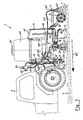
- FIG. 1 shows a device 1 for the care of riding floors 7, which is attached to a support vehicle 6, here a small agricultural tractor, which is only partially visible grown.
- the device 1 is supported by the carrying vehicle 6 and pulled and moved in the direction of travel 60 on the riding floor 7.
- the device 1 On its underside, the device 1 has various means 2, 3, 4 for loosening, mixing, smoothing and crumbling of the riding floor 7.
- the means 2 are formed by two transverse to the direction of travel 60 rows of harrow tines, which are resilient and adjustable in height on a device frame 10.2 are held. These means 2 provide during the movement of the device 1 for an intense loosening and mixing of the riding floor 7, the harrow tines act as a whirl due to their resilient properties in the movement of the device 1.
- Seen in the direction of travel 60 behind the means 2 is provided as a means 3 for smoothing the riding floor 7, a blade shield, which is held vertically adjustable and oscillating on the machine frame 10.2.
- the blade is deflected against the force of a spring when hitting obstacles backwards.
- a Krümlerwalze which is connected via a pair of trailing arms 40 articulated to the machine frame 10.2.
- the Krümlerwalze 4 rolls under load by their own weight and here with an additional Spring force load on the riding floor 7 from.
- a smooth roller preferably with a scraper, can be mounted on the trailing arms 40 if required.
- the device 1 is equipped with means for moistening the riding floor 7. These means are formed by two nozzle arrangements 5 through which a plurality of water jets on and / or in the riding floor 7 can be deployed.
- a water storage tank 50 which is mounted standing on a support frame 10.1.
- the container 50 On the upper side, the container 50 has a filling opening with a lid 50 ', through which a refueling with a water supply is possible in the open state.
- a first water conduit 51 in the form of a flexible hose is connected to the water reservoir 50.
- the water pipe 51 leads to a provided on the support vehicle 60 or coupled to the PTO water pump 52.
- This water pump 52 is covered by one of the rear wheels of the support vehicle 6 and therefore shown in dashed lines.
- the water line 51 continues to an adjusting device 53, with which the water supplied to two further water pipes 54, 54 'can be distributed adjustable.
- the setting device 53 is associated with a display device 53 'for displaying the water pressure and / or water flow.
- the adjustment device 53 with the associated display device 53 ' is arranged on an upwardly extending support arm 13 so that they are in the grip and field of view of a Guide the carrier vehicle 60 are.
- the support arm 13 is connected to the support frame 10.1 of the device 1.
- the two further water pipes 54, 54 ' which are also designed in the form of hoses, lead to a first nozzle tube 55 and a second nozzle tube 55'.
- the two nozzle tubes 55, 55 ' are spaced from each other transversely to the direction of travel 60 of the device 1 and are supported on the device frame 10.2.
- the first nozzle tube 55 lies in the region of the means 2 for loosening and mixing of the riding floor 7.
- the water jets 57 emerging from the nozzles of the first nozzle tube 55 thus reach particularly deeply into the riding floor 7 loosened deep here by the means 2.
- the second, rear nozzle tube 55 ' lies behind the means 4 formed by the Krümlerwalze crumbling of the riding floor 7.
- the water jets 57' emerging from the nozzles of this second nozzle tube 55 ' provide in particular for a near-surface humidification of the previously mechanically prepared and smoothed riding floor. 7
- the nozzle tubes 55, 55 ' are relative to the apparatus frame 10.2 adjustable, in particular rotatable about its longitudinal axis, fixed, so that the beam direction of the water jets 57, 57' set in the desired manner and thereby optimized.
- the individual nozzles may be interchangeable and / or adjustable, particularly with regard to water jet cone angle and droplet size, to accommodate different application conditions and riding floor materials.
- a relatively large droplet size is advantageous in riding floors made of sand, whereby at the same time the evaporation is limited; in finely divided riding floors, which tend to dust, rather smaller droplets are favorable for a good dust binding.
- the device 1 has two frames, namely the supporting frame 10.1, which is arranged at the top, and the device frame 10.2, which is arranged underneath.
- the above-arranged support frame 10.1 carries the water reservoir 50 with its filling opening 50 'with lid and the setting and display device 53, 53' with the associated water pipes 51, 54 and 54 '.
- the reservoir 50 carrying the upper support frame 10.1 has coupling elements 11 which are releasably connected to a present on the vehicle 6 three-point coupling 61.
- the support frame 10.1 can be raised and lowered together with the water reservoir 50.
- the arranged below the support frame 10.1 device frame 10.2 is also detachably connected by means of a device-side trailer hitch 11 'with a vehicle-mounted hitch 61'.
- the trailer hitch 61 'on the vehicle 6 is designed as a ball head, as is known for example from car towbars.
- the device frame 10.2 arranged at the bottom is pivotable about the trailer coupling 11 ', 61' both in the horizontal direction and in the vertical direction.
- a connection between the upper support frame 10.1 and the lower equipment frame 10.2 is formed here by two approximately vertically extending, flexible lifting elements 14, here two chains.
- the upper end of each lifting element 14 is struck on an outgoing from the support frame 10.1 boom 14 '.
- the lower end of the lifting elements 14 is attached to the device frame 10.2.
- the upper support frame 10.1 lifts over the lifting elements 14 at the same time the device frame 10.2 in a desired height, which is optimally adjusted for the respective processing of the riding floor 7 depending on its nature , Due to their flexibility, the lifting elements 14 allow sufficient lateral pivoting of the device frame 10.2 with the means 2, 3, 4 supported thereon relative to the upper support frame 10.1.
- the device frame 10.2 projecting relatively far to the rear beyond the rear of the vehicle 6 does not swing undesirably far when cornering, but follows the vehicle 6 like a trailer by virtue of its pivotability in the horizontal direction about the trailer coupling 11 ', 61'.
- the leadership of the device 1 and the vehicle 6 is simplified and there are damage to boundaries of the riding arena 7, such as gangs, or other objects on the riding arena, such. B. obstacles avoided.
- feet 58 are provided here on the support frame 10.1. These feet 58 are in each case in a guide sleeve 58 'vertically displaceable and fixable in desired heights. In the in FIG. 1 shown insertion position, the feet 58 are shifted so far upwards and fixed in this position, that they do not interfere with the movement of the device 1.
- the device 1 If the device 1 is not to be used, it is driven to a parking space. There, the feet 58 are released and extended down to the ground and fixed again in this position. Thereafter, then the device 1 by releasing the three-point clutch 11, 61 and the trailer hitch 11 ', 61' are separated from the vehicle 6. The device 1 is now standalone on its feet 58 until it is to be used again.
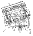
- FIG. 2a is the device 1 off FIG. 1 shown in plan view when driving straight ahead, in which case the vehicle 6 is not shown here.
- the upper support frame 10.1 which carries the water reservoir 50.
- the three-point clutch 11 61 of this support frame 10.1 is connected to the vehicle, not shown here.
- the four guide sleeves 58 ' are also connected to the frame 10.1, in which the associated feet 58 are vertically displaceable.
- the trailer hitch 11 'concealed Below the water reservoir 50 is the trailer hitch 11 'concealed, which is therefore shown in dashed lines.
- the support arm 13 To the left of the trailer hitch 11 'is above this the support arm 13 which is connected to the support frame 10.1 and carries at its upper end the setting and display device 53, 53' in the field of vision and grip of a driver.
- the lower device frame 10.2 Below the support frame 10.1 and behind this, ie in FIG. 2a in the right area, is the lower device frame 10.2. With this equipment frame 10.2 the trailer hitch 11 'is connected. With the equipment frame 10.2, the means 2, 3, 4 and 5 for loosening, mixing, smoothing, crumbling and moistening of the riding floor 7 are further connected.
- the nozzle assemblies 5 are supplied with water at the two nozzle tubes 55, 55'.
- FIG. 2a the device 1 is shown when driving straight ahead.
- FIG. 2b the device 1 is shown when cornering in a right turn.
- the above the three-point clutch 11, 61 connected to the vehicle, not shown upper support frame 10.1 has the same orientation as the vehicle, since a pivoting of the support frame 10.1 relative to the vehicle in the horizontal plane via the three-point coupling 11, 61 is not possible.
- the lower device frame 10.2 has a pivoting freedom relative to the vehicle and also relative to the support frame 10.1 about its trailer hitch 11 '.
- the device frame runs 10.2 with the means arranged thereon 2 to 5 on the Krümmlerwalze 4 like a Einachsan vonr behind the vehicle ago, in the cornering of the device frame 10.2 passes through a smaller radius than the device frame at a rigid connection to the support frame 10.1 and to the vehicle.
- the flexible lifting elements 14 in the form of the two chains allow the pivoting of the machine frame 10.2 relative to the upper support frame 10.1, as is clear from FIG. 2b is apparent. At the same time, however, still carries the Upper support frame 10.1 a part of the weight of the device frame 10.2 with the means 2 to 5 arranged thereon.
- the water pipes 54, 54 'in the form of hoses flexibly adapt to the pivoting of the machine frame 10.2 relative to the support frame 10.1.
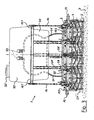
- FIG. 3 Finally, the device 1 according to the FIGS. 1 . 2a and 2 B in a rear view, now again straight ahead. Top in FIG. 3 the water reservoir 50 with its filling opening 50 'with lid recognizable. Concealed by the water reservoir 50 is the adjustment 53 before this.
- the water reservoir 50 is supported by the support frame 10.1. From the support frame 10.1, the feet 58 extend downwards, which are displaceable in the guide sleeves 58 ', which in turn are connected to the support frame 10.1.
- the device frame 10.2 Under the support frame 10.1 and the water reservoir 50 is the device frame 10.2, where the means 2 to 5 are supported for the care of the riding floor 7. At the viewer facing the rear nozzle tube 55 ', the individual nozzles 56' can be seen, through each of which a water jet 57 'in the direction of the riding floor 7 can be brought out. At the far left and far right of the device frame 10.2, the two band rolls 12 are visible.
- FIG. 3 illustrates a lateral deflection of the device frame 10.2 relative to the support frame 10.1 due to the flexibility of the lifting elements 14 in a sufficiently large extent possible.
Landscapes
- Engineering & Computer Science (AREA)
- Life Sciences & Earth Sciences (AREA)
- Mechanical Engineering (AREA)
- Soil Sciences (AREA)
- Environmental Sciences (AREA)
- Architecture (AREA)
- Civil Engineering (AREA)
- Structural Engineering (AREA)
- Mining & Mineral Resources (AREA)
- Vehicle Cleaning, Maintenance, Repair, Refitting, And Outriggers (AREA)
- Soil Working Implements (AREA)
- Road Repair (AREA)
- Catching Or Destruction (AREA)
- Air-Conditioning For Vehicles (AREA)
- Massaging Devices (AREA)
- Prevention Of Fouling (AREA)
Claims (16)
- Appareil (1) pour l'entretien de terrains d'équitation (7), notamment dans des manèges couverts et sur des manèges, l'appareil (1) pouvant être déplacé au-dessus du terrain d'équitation (7) au moyen d'un véhicule à traction ou porteur (6) auquel il peut être accouplé, l'appareil (1) présentant des moyens (2, 3, 4) pour assouplir, mélanger, lisser, émietter et/ou compacter le terrain d'équitation (7), l'appareil (1) présentant en outre au moins un agencement de buses (5) à travers lequel de l'eau pour mouiller le terrain d'équitation (7) peut être épandue sur et/ou dans celui-ci pendant le déplacement de l'appareil (1), et l'appareil (1), vu dans sa direction de déplacement (60), étant équipé à l'avant d'éléments d'accouplement (11, 11') qui peuvent être reliés de manière amovible à au moins un accouplement standardisé (61, 61') du véhicule à traction ou porteur (6), caractérisé en ce- que l'appareil (1) présente en tant que premier élément d'accouplement un attelage à trois points (11) qui est relié du côté de l'appareil à un cadre porteur supérieur (10.1) portant un réservoir d'eau (50),- que l'appareil (1) présente en tant que deuxième élément d'accouplement un dispositif d'attelage de remorque (11') qui est relié du côté de l'appareil à un cadre d'appareil inférieur (10.2) portant les moyens (2, 3, 4) pour assouplir, mélanger, lisser, émietter et/ou compacter le terrain d'équitation (7) et l'agencement de buses (5) qui peut s'appuyer dans sa région arrière en roulant sur le sous-sol, et- que le cadre d'appareil inférieur (10.2) peut pivoter par rapport au cadre porteur supérieur (10.1) dans la direction horizontale et verticale autour du dispositif d'attelage de remorque (11').
- Appareil selon la revendication 1, caractérisé en ce que le cadre porteur (10.1) est réglable en hauteur au moyen de l'attelage à trois points (11, 61) depuis le véhicule à traction ou porteur (6) et qu'au moins un élément de levage flexible (14), de préférence une chaîne ou un câble, est guidé par le cadre porteur (10.1) vers le bas vers le cadre d'appareil (10.2).
- Appareil selon la revendication 1 ou 2, caractérisé en ce que le réservoir d'eau (50) est relié par le biais d'une conduite d'eau (51, 54, 54') sous la forme d'au moins un tuyau flexible à l'agencement de buses (5).
- Appareil selon la revendication 3, caractérisé en ce qu'une pompe à eau (52) est prévue dans l'étendue de la conduite d'eau (51, 54, 54') entre le réservoir d'eau (50) et l'agencement de buses (5).
- Appareil selon la revendication 3, caractérisé en ce que le réservoir d'eau (50) peut être fermé de manière étanche et être mis sous pression par une pompe à air.
- Appareil selon la revendication 4 ou 5, caractérisé en ce que la pompe à eau (52) ou la pompe à air peut être entraînée par le véhicule à traction ou porteur (6).
- Appareil selon l'une quelconque des revendications précédentes, caractérisé en ce que la pression de l'eau amenée à l'agencement de buses (5) et/ou la quantité de l'eau épandue par l'agencement de buses (5) peut/peuvent être régulée(s) par un dispositif de réglage (53).
- Appareil selon la revendication 7, caractérisé en ce qu'un dispositif d'affichage (53') pour l'affichage de la pression d'eau et/ou du débit d'eau est associé au dispositif de réglage (53).
- Appareil selon la revendication 7 ou 8, caractérisé en ce que le dispositif de réglage (53) est disposé à portée de main et/ou le dispositif d'affichage (53') dans la zone visible d'un opérateur guidant l'appareil (1) ou le véhicule à traction ou porteur associé (6).
- Appareil selon l'une quelconque des revendications précédentes, caractérisé en ce que l'agencement de buses (5) est formé par au moins une lance (55, 55') s'étendant de manière transversale à la direction de déplacement (60) de l'appareil (1) avec plusieurs buses (56, 56') disposées de manière écartée les unes des autres dans la direction longitudinale de la lance.
- Appareil selon la revendication 10, caractérisé en ce que les buses (56, 56') peuvent être réglées individuellement dans leur forme de jet et/ou direction de jet.
- Appareil selon la revendication 10 ou 11, caractérisé en ce qu'il présente deux lances (55, 55') écartées l'une de l'autre dans la direction de déplacement (60) de l'appareil (1), s'étendant parallèlement l'une à l'autre, ou plus.
- Appareil selon la revendication 12, caractérisé en ce qu'une première lance (55) est disposée dans la région du moyen (2) pour assouplir et/ou mélanger le terrain d'équitation (7) et une deuxième lance (55') est disposée dans la région du moyen (4) pour émietter le terrain d'équitation (7).
- Appareil selon l'une quelconque des revendications 10 à 13, caractérisé en ce que la/chaque lance (55, 55') peut être déplacée par rapport au reste de l'appareil (1) dans sa position et/ou son orientation et peut être fixée dans une position et/ou orientation souhaitée(s).
- Appareil selon l'une quelconque des revendications précédentes, caractérisé en ce que l'appareil (1), vu dans sa direction de déplacement (60), présente de l'avant vers l'arrière de manière successive au moins une série de pointes d'étrille élastiques, réglables en hauteur en tant que moyen (2) pour assouplir et mélanger le terrain d'équitation (7), une lame niveleuse suspendue en oscillant, réglable en hauteur en tant que moyen (3) pour lisser le terrain d'équitation (7) et soit un rouleau émotteur courant, guidé le long de guidons longitudinaux (40) en tant que moyen (4) pour émietter le terrain d'équitation (7), soit un rouleau de lissage courant, guidé le long de guidons longitudinaux (40) en tant que moyen (4) pour lisser et compacter le terrain d'équitation (7) davantage.
- Appareil selon la revendication 15, caractérisé en ce que le rouleau de lissage servant de moyen (4) pour lisser et compacter le terrain d'équitation (7) davantage est équipé d'au moins un racloir.
Applications Claiming Priority (4)
| Application Number | Priority Date | Filing Date | Title |
|---|---|---|---|
| DE20307668U DE20307668U1 (de) | 2003-05-16 | 2003-05-16 | Gerät für die Pflege von Reitböden |
| DE20307668U | 2003-05-16 | ||
| DE202004000535U | 2004-01-15 | ||
| DE202004000535U DE202004000535U1 (de) | 2003-05-16 | 2004-01-15 | Gerät für die Pflege von Reitböden |
Publications (3)
| Publication Number | Publication Date |
|---|---|
| EP1477610A2 EP1477610A2 (fr) | 2004-11-17 |
| EP1477610A3 EP1477610A3 (fr) | 2005-08-03 |
| EP1477610B1 true EP1477610B1 (fr) | 2008-10-29 |
Family
ID=28459127
Family Applications (1)
| Application Number | Title | Priority Date | Filing Date |
|---|---|---|---|
| EP04011123A Expired - Lifetime EP1477610B1 (fr) | 2003-05-16 | 2004-05-11 | Dispositif d'entretien de terrain d'équitation |
Country Status (4)
| Country | Link |
|---|---|
| EP (1) | EP1477610B1 (fr) |
| AT (1) | ATE412801T1 (fr) |
| DE (3) | DE20307668U1 (fr) |
| DK (1) | DK1477610T3 (fr) |
Families Citing this family (18)
| Publication number | Priority date | Publication date | Assignee | Title |
|---|---|---|---|---|
| EP1654919B1 (fr) * | 2004-11-05 | 2009-02-25 | ROTER ITALIA S.r.l. | Machine agricole pour incorporer des substances liquides dans le sol |
| DE102005004238A1 (de) * | 2005-01-28 | 2006-08-17 | Bjj Kleinmaschinen Gmbh | Vorrichtung zur Bearbeitung einer Reitbahn |
| DE602006001663D1 (de) * | 2005-02-28 | 2008-08-21 | Roter Italia S R L | Landmaschine zur Einarbeitung von flüssigen Substanzen in den Boden |
| DE202006020808U1 (de) | 2006-06-16 | 2010-05-20 | Handschuh Gmbh | Vorrichtung zum Abziehen eines Bodens eines Reitplatzes |
| CN101864723B (zh) * | 2010-07-01 | 2011-09-14 | 中铁科工集团有限公司 | 共振破碎机 |
| CN102505656B (zh) * | 2011-04-19 | 2014-12-24 | 长沙中联重科环卫机械有限公司 | 路面清洁车辆及其路面清洁方法 |
| CN104871671A (zh) * | 2015-06-11 | 2015-09-02 | 安徽康成工业产品设计有限公司 | 一种微耕机具有撒水功能的装置 |
| DE102015008389A1 (de) | 2015-06-29 | 2016-12-29 | Thomas Loeffler | Manuelles Planiergerät für Granulat und sonstiges Schüttgut, insbesondere zum Einebenen von Reitbahnen, mit durchgehender Griffstange |
| CN107419688B (zh) * | 2017-08-14 | 2019-01-15 | 左梅兰 | 一种建筑施工用保护空气的设备 |
| CN107476239A (zh) * | 2017-09-15 | 2017-12-15 | 无锡市湖昌机械制造有限公司 | 自动驾驶洒水清洗车 |
| CN107653767B (zh) * | 2017-11-08 | 2021-11-16 | 台州锐祥机械设备有限公司 | 一种基于机械工程的实用型道路用混凝土压实机 |
| CN108018904B (zh) * | 2017-11-30 | 2020-07-17 | 嘉兴市瑞鑫塑业有限公司 | 一种石油管道铺设用挖沟设备 |
| DE202018101438U1 (de) | 2018-03-14 | 2018-06-12 | Rampelmann & Spliethoff GmbH & Co. KG | Gerät für die Pflege von Reitböden |
| CN108476625B (zh) * | 2018-04-26 | 2020-05-08 | 咸宁职业技术学院 | 一种喷洒水翻土农机装置 |
| CN109220006B (zh) * | 2018-11-20 | 2022-03-22 | 吉林大学 | 一种低压水射流式深松机 |
| CN109999588A (zh) * | 2019-04-24 | 2019-07-12 | 王科程 | 一种室内建筑施工用除尘装置 |
| CN113853864B (zh) * | 2021-09-24 | 2022-05-31 | 上海市园林设计研究总院有限公司 | 一种滨海绿地排盐碱施工用土壤改良装置及方法 |
| WO2025049237A1 (fr) * | 2023-08-31 | 2025-03-06 | Idaho Asphalt Supply, Inc. | Stabilisation et régulation de poussière à partir d'une route rdimentaire |
Family Cites Families (9)
| Publication number | Priority date | Publication date | Assignee | Title |
|---|---|---|---|---|
| US2870554A (en) * | 1954-03-25 | 1959-01-27 | Marvin Landplane Company | Combination agricultural implement |
| US3782634A (en) * | 1972-12-15 | 1974-01-01 | Swenson Spreader & Mfg Co | Vehicle mounted liquid distributor apparatus |
| US3970012A (en) * | 1975-02-21 | 1976-07-20 | Jones Sr Donald F | Soil agitating device |
| GB2029475B (en) * | 1978-09-07 | 1982-10-20 | Sisis Equip | Apparatus for the treatment of surfaces |
| DE3032275A1 (de) * | 1980-08-27 | 1982-04-08 | Helmut 7000 Stuttgart Sigloch | Fahrbare landwirtschaftliche maschine |
| US4677787A (en) * | 1984-10-15 | 1987-07-07 | Said Ronald S | Apparatus for mounting application heads to an agricultural implement |
| DE4030204C2 (de) | 1990-09-24 | 1994-09-22 | Wolf Geraete Gmbh Vertrieb | Maschine zur Bearbeitung von Tennenflächen |
| JPH0533310A (ja) | 1991-08-02 | 1993-02-09 | Toomen Constr Kk | 排水性舗装の強化剤散布装置 |
| DE10137802A1 (de) | 2001-08-06 | 2003-03-06 | Juergen Repenning | Vorrichtung zur selbstfahrenden Bearbeitung einer Reitbahn |
-
2003
- 2003-05-16 DE DE20307668U patent/DE20307668U1/de not_active Expired - Lifetime
-
2004
- 2004-01-15 DE DE202004000535U patent/DE202004000535U1/de not_active Expired - Lifetime
- 2004-05-11 AT AT04011123T patent/ATE412801T1/de not_active IP Right Cessation
- 2004-05-11 DK DK04011123T patent/DK1477610T3/da active
- 2004-05-11 EP EP04011123A patent/EP1477610B1/fr not_active Expired - Lifetime
- 2004-05-11 DE DE502004008331T patent/DE502004008331D1/de not_active Expired - Lifetime
Also Published As
| Publication number | Publication date |
|---|---|
| DE502004008331D1 (de) | 2008-12-11 |
| DE20307668U1 (de) | 2003-09-18 |
| ATE412801T1 (de) | 2008-11-15 |
| DK1477610T3 (da) | 2009-02-16 |
| EP1477610A2 (fr) | 2004-11-17 |
| EP1477610A3 (fr) | 2005-08-03 |
| DE202004000535U1 (de) | 2004-09-30 |
Similar Documents
| Publication | Publication Date | Title |
|---|---|---|
| EP1477610B1 (fr) | Dispositif d'entretien de terrain d'équitation | |
| DE69404865T2 (de) | Landwirtschaftliche sprüheinheit und deren luftstromerzeuger | |
| DE60004995T3 (de) | Landwirtschaftliche Maschine und Vorrichtung | |
| DE102018124626A1 (de) | Landwirtschaftliche Verteilvorrichtung und Verfahren zu deren Überführung zwischen einer Arbeitsstellung und einer Transportstellung | |
| EP0679326B1 (fr) | Chariot trainé avec roues porteurs | |
| DE3509040C2 (fr) | ||
| EP0066237A1 (fr) | Tête de récolte pour récolteuses pour récolter des denrées arrangées en files à distances variables | |
| WO2021115824A1 (fr) | Support d'équipement pour entretien de gazon | |
| EP0289517A1 (fr) | Procede et dispositif d'ameublissement du sol. | |
| DE2528930A1 (de) | Tragrahmen fuer landwirtschaftliche maschinen und geraete | |
| DE2044566C3 (de) | Streugerät | |
| DE19608579C2 (de) | Anhängevorrichtung | |
| DE3420617A1 (de) | Streugeraet, insbesondere mineraldungstreuer | |
| DE2752646A1 (de) | Vorrichtung zum anheben von erdboden ohne wenden | |
| DE202018101438U1 (de) | Gerät für die Pflege von Reitböden | |
| EP3466233A1 (fr) | Étrille lourde pour un dispositif de traitement de sol | |
| DE60010692T2 (de) | Verbessertes an einem anhänger festgemachtes sprühgerät | |
| DE19907022B4 (de) | Mietenumsetzer, insbesondere Trapez-Mietenumsetzer | |
| DE2701695C2 (de) | Verfahren und Vorrichtung zum Einbringen eines Veredlungsmittels in das Erdreich | |
| DE3308942A1 (de) | Bodenbearbeitungsmaschine, insbesondere kreiselegge | |
| EP1606985B1 (fr) | Machine agricole, forestière ou de jardinage | |
| DE69910683T2 (de) | Sähmaschine | |
| DE202004009107U1 (de) | Gerät für die Pflege von Reitböden | |
| DE10030263A1 (de) | Anhängevorrichtung | |
| EP4666855B1 (fr) | Machine de pose d'appâts |
Legal Events
| Date | Code | Title | Description |
|---|---|---|---|
| PUAI | Public reference made under article 153(3) epc to a published international application that has entered the european phase |
Free format text: ORIGINAL CODE: 0009012 |
|
| AK | Designated contracting states |
Kind code of ref document: A2 Designated state(s): AT BE BG CH CY CZ DE DK EE ES FI FR GB GR HU IE IT LI LU MC NL PL PT RO SE SI SK TR |
|
| AX | Request for extension of the european patent |
Extension state: AL HR LT LV MK |
|
| PUAL | Search report despatched |
Free format text: ORIGINAL CODE: 0009013 |
|
| AK | Designated contracting states |
Kind code of ref document: A3 Designated state(s): AT BE BG CH CY CZ DE DK EE ES FI FR GB GR HU IE IT LI LU MC NL PL PT RO SE SI SK TR |
|
| AX | Request for extension of the european patent |
Extension state: AL HR LT LV MK |
|
| RIC1 | Information provided on ipc code assigned before grant |
Ipc: 7A 01B 35/32 B Ipc: 7E 01C 23/082 B Ipc: 7E 01C 21/00 B Ipc: 7A 01B 51/04 B Ipc: 7E 01H 3/02 B Ipc: 7E 01C 23/06 A Ipc: 7A 01B 49/02 B |
|
| 17P | Request for examination filed |
Effective date: 20060127 |
|
| AKX | Designation fees paid |
Designated state(s): AT BE BG CH CY CZ DE DK EE ES FI FR GB GR HU IE IT LI LU MC NL PL PT RO SE SI SK TR |
|
| 17Q | First examination report despatched |
Effective date: 20070604 |
|
| GRAP | Despatch of communication of intention to grant a patent |
Free format text: ORIGINAL CODE: EPIDOSNIGR1 |
|
| GRAS | Grant fee paid |
Free format text: ORIGINAL CODE: EPIDOSNIGR3 |
|
| GRAA | (expected) grant |
Free format text: ORIGINAL CODE: 0009210 |
|
| AK | Designated contracting states |
Kind code of ref document: B1 Designated state(s): AT BE BG CH CY CZ DE DK EE ES FI FR GB GR HU IE IT LI LU MC NL PL PT RO SE SI SK TR |
|
| REG | Reference to a national code |
Ref country code: GB Ref legal event code: FG4D Free format text: NOT ENGLISH |
|
| REG | Reference to a national code |
Ref country code: CH Ref legal event code: EP |
|
| REG | Reference to a national code |
Ref country code: IE Ref legal event code: FG4D Free format text: LANGUAGE OF EP DOCUMENT: GERMAN |
|
| REF | Corresponds to: |
Ref document number: 502004008331 Country of ref document: DE Date of ref document: 20081211 Kind code of ref document: P |
|
| REG | Reference to a national code |
Ref country code: CH Ref legal event code: NV Representative=s name: INTERPAT LAW AG |
|
| REG | Reference to a national code |
Ref country code: DK Ref legal event code: T3 |
|
| REG | Reference to a national code |
Ref country code: SE Ref legal event code: TRGR |
|
| PG25 | Lapsed in a contracting state [announced via postgrant information from national office to epo] |
Ref country code: ES Free format text: LAPSE BECAUSE OF FAILURE TO SUBMIT A TRANSLATION OF THE DESCRIPTION OR TO PAY THE FEE WITHIN THE PRESCRIBED TIME-LIMIT Effective date: 20090209 Ref country code: BG Free format text: LAPSE BECAUSE OF FAILURE TO SUBMIT A TRANSLATION OF THE DESCRIPTION OR TO PAY THE FEE WITHIN THE PRESCRIBED TIME-LIMIT Effective date: 20090129 |
|
| PG25 | Lapsed in a contracting state [announced via postgrant information from national office to epo] |
Ref country code: PL Free format text: LAPSE BECAUSE OF FAILURE TO SUBMIT A TRANSLATION OF THE DESCRIPTION OR TO PAY THE FEE WITHIN THE PRESCRIBED TIME-LIMIT Effective date: 20081029 Ref country code: SI Free format text: LAPSE BECAUSE OF FAILURE TO SUBMIT A TRANSLATION OF THE DESCRIPTION OR TO PAY THE FEE WITHIN THE PRESCRIBED TIME-LIMIT Effective date: 20081029 Ref country code: FI Free format text: LAPSE BECAUSE OF FAILURE TO SUBMIT A TRANSLATION OF THE DESCRIPTION OR TO PAY THE FEE WITHIN THE PRESCRIBED TIME-LIMIT Effective date: 20081029 Ref country code: PT Free format text: LAPSE BECAUSE OF FAILURE TO SUBMIT A TRANSLATION OF THE DESCRIPTION OR TO PAY THE FEE WITHIN THE PRESCRIBED TIME-LIMIT Effective date: 20090330 |
|
| PG25 | Lapsed in a contracting state [announced via postgrant information from national office to epo] |
Ref country code: EE Free format text: LAPSE BECAUSE OF FAILURE TO SUBMIT A TRANSLATION OF THE DESCRIPTION OR TO PAY THE FEE WITHIN THE PRESCRIBED TIME-LIMIT Effective date: 20081029 Ref country code: RO Free format text: LAPSE BECAUSE OF FAILURE TO SUBMIT A TRANSLATION OF THE DESCRIPTION OR TO PAY THE FEE WITHIN THE PRESCRIBED TIME-LIMIT Effective date: 20081029 |
|
| PGFP | Annual fee paid to national office [announced via postgrant information from national office to epo] |
Ref country code: DK Payment date: 20090526 Year of fee payment: 6 Ref country code: IE Payment date: 20090618 Year of fee payment: 6 Ref country code: NL Payment date: 20090531 Year of fee payment: 6 |
|
| PG25 | Lapsed in a contracting state [announced via postgrant information from national office to epo] |
Ref country code: CZ Free format text: LAPSE BECAUSE OF FAILURE TO SUBMIT A TRANSLATION OF THE DESCRIPTION OR TO PAY THE FEE WITHIN THE PRESCRIBED TIME-LIMIT Effective date: 20081029 Ref country code: IT Free format text: LAPSE BECAUSE OF FAILURE TO SUBMIT A TRANSLATION OF THE DESCRIPTION OR TO PAY THE FEE WITHIN THE PRESCRIBED TIME-LIMIT Effective date: 20081029 |
|
| PGFP | Annual fee paid to national office [announced via postgrant information from national office to epo] |
Ref country code: AT Payment date: 20090615 Year of fee payment: 6 Ref country code: FR Payment date: 20090528 Year of fee payment: 6 Ref country code: SE Payment date: 20090526 Year of fee payment: 6 |
|
| PLBE | No opposition filed within time limit |
Free format text: ORIGINAL CODE: 0009261 |
|
| STAA | Information on the status of an ep patent application or granted ep patent |
Free format text: STATUS: NO OPPOSITION FILED WITHIN TIME LIMIT |
|
| PG25 | Lapsed in a contracting state [announced via postgrant information from national office to epo] |
Ref country code: SK Free format text: LAPSE BECAUSE OF FAILURE TO SUBMIT A TRANSLATION OF THE DESCRIPTION OR TO PAY THE FEE WITHIN THE PRESCRIBED TIME-LIMIT Effective date: 20081029 |
|
| PGFP | Annual fee paid to national office [announced via postgrant information from national office to epo] |
Ref country code: BE Payment date: 20090619 Year of fee payment: 6 |
|
| 26N | No opposition filed |
Effective date: 20090730 |
|
| PGFP | Annual fee paid to national office [announced via postgrant information from national office to epo] |
Ref country code: CH Payment date: 20090615 Year of fee payment: 6 |
|
| PGFP | Annual fee paid to national office [announced via postgrant information from national office to epo] |
Ref country code: GB Payment date: 20090527 Year of fee payment: 6 |
|
| PG25 | Lapsed in a contracting state [announced via postgrant information from national office to epo] |
Ref country code: MC Free format text: LAPSE BECAUSE OF NON-PAYMENT OF DUE FEES Effective date: 20090531 |
|
| PG25 | Lapsed in a contracting state [announced via postgrant information from national office to epo] |
Ref country code: GR Free format text: LAPSE BECAUSE OF FAILURE TO SUBMIT A TRANSLATION OF THE DESCRIPTION OR TO PAY THE FEE WITHIN THE PRESCRIBED TIME-LIMIT Effective date: 20090130 |
|
| BERE | Be: lapsed |
Owner name: RAMPELMANN & SPLIETHOFF OHG Effective date: 20100531 |
|
| REG | Reference to a national code |
Ref country code: NL Ref legal event code: V1 Effective date: 20101201 |
|
| REG | Reference to a national code |
Ref country code: CH Ref legal event code: PL |
|
| REG | Reference to a national code |
Ref country code: DK Ref legal event code: EBP |
|
| GBPC | Gb: european patent ceased through non-payment of renewal fee |
Effective date: 20100511 |
|
| PG25 | Lapsed in a contracting state [announced via postgrant information from national office to epo] |
Ref country code: AT Free format text: LAPSE BECAUSE OF NON-PAYMENT OF DUE FEES Effective date: 20100511 |
|
| EUG | Se: european patent has lapsed | ||
| REG | Reference to a national code |
Ref country code: FR Ref legal event code: ST Effective date: 20110131 |
|
| PG25 | Lapsed in a contracting state [announced via postgrant information from national office to epo] |
Ref country code: LI Free format text: LAPSE BECAUSE OF NON-PAYMENT OF DUE FEES Effective date: 20100531 Ref country code: CH Free format text: LAPSE BECAUSE OF NON-PAYMENT OF DUE FEES Effective date: 20100531 |
|
| REG | Reference to a national code |
Ref country code: IE Ref legal event code: MM4A |
|
| PG25 | Lapsed in a contracting state [announced via postgrant information from national office to epo] |
Ref country code: NL Free format text: LAPSE BECAUSE OF NON-PAYMENT OF DUE FEES Effective date: 20101201 Ref country code: BE Free format text: LAPSE BECAUSE OF NON-PAYMENT OF DUE FEES Effective date: 20100531 Ref country code: SE Free format text: LAPSE BECAUSE OF NON-PAYMENT OF DUE FEES Effective date: 20100512 |
|
| PG25 | Lapsed in a contracting state [announced via postgrant information from national office to epo] |
Ref country code: IE Free format text: LAPSE BECAUSE OF NON-PAYMENT OF DUE FEES Effective date: 20100511 Ref country code: DK Free format text: LAPSE BECAUSE OF NON-PAYMENT OF DUE FEES Effective date: 20100531 Ref country code: LU Free format text: LAPSE BECAUSE OF NON-PAYMENT OF DUE FEES Effective date: 20090511 |
|
| PG25 | Lapsed in a contracting state [announced via postgrant information from national office to epo] |
Ref country code: FR Free format text: LAPSE BECAUSE OF NON-PAYMENT OF DUE FEES Effective date: 20100531 |
|
| PG25 | Lapsed in a contracting state [announced via postgrant information from national office to epo] |
Ref country code: HU Free format text: LAPSE BECAUSE OF FAILURE TO SUBMIT A TRANSLATION OF THE DESCRIPTION OR TO PAY THE FEE WITHIN THE PRESCRIBED TIME-LIMIT Effective date: 20090430 |
|
| PG25 | Lapsed in a contracting state [announced via postgrant information from national office to epo] |
Ref country code: GB Free format text: LAPSE BECAUSE OF NON-PAYMENT OF DUE FEES Effective date: 20100511 |
|
| PG25 | Lapsed in a contracting state [announced via postgrant information from national office to epo] |
Ref country code: TR Free format text: LAPSE BECAUSE OF FAILURE TO SUBMIT A TRANSLATION OF THE DESCRIPTION OR TO PAY THE FEE WITHIN THE PRESCRIBED TIME-LIMIT Effective date: 20081029 |
|
| PG25 | Lapsed in a contracting state [announced via postgrant information from national office to epo] |
Ref country code: CY Free format text: LAPSE BECAUSE OF FAILURE TO SUBMIT A TRANSLATION OF THE DESCRIPTION OR TO PAY THE FEE WITHIN THE PRESCRIBED TIME-LIMIT Effective date: 20081029 |
|
| PGFP | Annual fee paid to national office [announced via postgrant information from national office to epo] |
Ref country code: DE Payment date: 20110913 Year of fee payment: 8 |
|
| REG | Reference to a national code |
Ref country code: DE Ref legal event code: R119 Ref document number: 502004008331 Country of ref document: DE Effective date: 20121201 |
|
| PG25 | Lapsed in a contracting state [announced via postgrant information from national office to epo] |
Ref country code: DE Free format text: LAPSE BECAUSE OF NON-PAYMENT OF DUE FEES Effective date: 20121201 |