EP1477617A2 - Piège à odeurs et dispositif anti-retour - Google Patents
Piège à odeurs et dispositif anti-retour Download PDFInfo
- Publication number
- EP1477617A2 EP1477617A2 EP04076419A EP04076419A EP1477617A2 EP 1477617 A2 EP1477617 A2 EP 1477617A2 EP 04076419 A EP04076419 A EP 04076419A EP 04076419 A EP04076419 A EP 04076419A EP 1477617 A2 EP1477617 A2 EP 1477617A2
- Authority
- EP
- European Patent Office
- Prior art keywords
- seal
- passage
- seal according
- opening
- flow
- Prior art date
- Legal status (The legal status is an assumption and is not a legal conclusion. Google has not performed a legal analysis and makes no representation as to the accuracy of the status listed.)
- Withdrawn
Links
- 239000012530 fluid Substances 0.000 claims abstract description 4
- 239000007788 liquid Substances 0.000 claims description 7
- 230000007704 transition Effects 0.000 claims description 7
- 238000011144 upstream manufacturing Methods 0.000 claims description 3
- 238000001746 injection moulding Methods 0.000 claims description 2
- 229910052710 silicon Inorganic materials 0.000 claims description 2
- 239000010703 silicon Substances 0.000 claims description 2
- 210000004209 hair Anatomy 0.000 abstract description 3
- 230000005484 gravity Effects 0.000 description 1
- 230000005923 long-lasting effect Effects 0.000 description 1
- 238000005259 measurement Methods 0.000 description 1
- 239000002184 metal Substances 0.000 description 1
- 238000007789 sealing Methods 0.000 description 1
- XLYOFNOQVPJJNP-UHFFFAOYSA-N water Substances O XLYOFNOQVPJJNP-UHFFFAOYSA-N 0.000 description 1
Images
Classifications
-
- F—MECHANICAL ENGINEERING; LIGHTING; HEATING; WEAPONS; BLASTING
- F16—ENGINEERING ELEMENTS AND UNITS; GENERAL MEASURES FOR PRODUCING AND MAINTAINING EFFECTIVE FUNCTIONING OF MACHINES OR INSTALLATIONS; THERMAL INSULATION IN GENERAL
- F16K—VALVES; TAPS; COCKS; ACTUATING-FLOATS; DEVICES FOR VENTING OR AERATING
- F16K15/00—Check valves
- F16K15/14—Check valves with flexible valve members
- F16K15/144—Check valves with flexible valve members the closure elements being fixed along all or a part of their periphery
- F16K15/147—Check valves with flexible valve members the closure elements being fixed along all or a part of their periphery the closure elements having specially formed slits or being of an elongated easily collapsible form
-
- E—FIXED CONSTRUCTIONS
- E03—WATER SUPPLY; SEWERAGE
- E03C—DOMESTIC PLUMBING INSTALLATIONS FOR FRESH WATER OR WASTE WATER; SINKS
- E03C1/00—Domestic plumbing installations for fresh water or waste water; Sinks
- E03C1/12—Plumbing installations for waste water; Basins or fountains connected thereto; Sinks
- E03C1/28—Odour seals
- E03C1/298—Odour seals consisting only of non-return valve
Definitions
- the object is, o.a., one or more of the following: large flow-through capacity; avoidance of getting plugged by e.g. hairs; the possibility to fabricate the seal by injection moulding; the possibility to apply the seal in a horizontal position; long lasting; to avoid that the seal can be turned inside out by a back flow.
- the seal preferably has one or more of the following features: made of silicon; a wall thickness below 1 mm, preferably below 0.6 mm, more preferably between 0.1 and 0.5 mm in the area wherein the walls in rest bear sealingly against each other; shaped such that the seal by nature has an upstream open inflow opening, preferably substantially circular, and downstream a closed outflow opening, preferably substantially gap like, wherein said outflow opening automatically opens by moving away from each other of the wall parts on both sides of the gap due to flexural deformation; a tapered, preferably bulged, transition area from the inflow opening towards the outflow opening; an active flow-through opening, preferably in the transition area, of which the dimension increases in downstream direction; a projection, preferably in the radial direction, preferably in the transition area, wherein walls are moved apart with opened uitflow opening; a gap dimension, preferably at the outflow opening, larger than a dimension of the inflow opening or a dimension of the transition area, preferably disregarding a possible projection.
- a seal such as the in here or in EP-A-1174549 disclosed, or another seal with a by nature closed outflow opening of which at least one of the mutually bearing walls moves apart while deforming by flexure during automatically opening of the outflow opening when a liquid stream passess therethrough, such as e.g. according to EP-A-0941433, is used horizontally, it is prefered to support at least a part of the piece of the seal wherein the walls are sealingly mutually bearing and can easily move away from each other, such that if the liquid stream through the seal is absent, said piece has substantially the shape according to the upright (vertical) working position. Therefor said piece is preferably supported by a non-circular wall of e.g. a tube wherein the seal is mounted. Thus the sealing of the gap is guaranteed.
- the invention is also concerned with a seal with an inflow opening that should forcibly kept open, e.g based on information in EP-A-0941433.
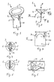
- the invention is further exemplified by the enclosed drawing showing a non-limiting prefered embodiment in its natural, unloaded condition.
- the seal 1 is mounted in a plastic or metal, cylindric, drain tube 2 (fig. 6) running to the public sewer and connected to a sanitary device. Liquid to be drained to the sewer flows by gravity action in the direction of arrow A (fig. 2) through the seal 1. The seal 1 prevents that in the direction opposite arrow A at least gassess and preferably also liquids pass and enter the living space.
- the seal can be mounted in a tub 2 that extends in a vertical, horizontal or any desired position in between. Fig. 6 shows mounting in a horizontal tube 2.
- the seal has a radially projecting annular flange 3 for mounting purposes.
- the annular flange bears at a seat 13 projecting from the inner wall of the tube 2.
- a thin walled cylindrical part 4 joins, which merges in two radially opposite, toward the inner side bent, flattened, thin walled parts 5 that merge into flat, thin walled strips 6 which mutually bear over their complete lengt and width, such that between said parts 5 a flow trhough opening 15 is present (fig. 4) which gradually narrows in the direction of arrow A and merges into a closed gap 7 between de strips 6 (fig. 5).
- the longitudinal edges 10 of the strips 6 are mutually connected in a fluid tight manner.
- the strips 6 have buckles 8 and 9.
- the seal 1 corresponds to EP-A-1174549.
- the strips 6 are wider than the cylindrical part 4 and thus the gap 7 is longer than the inner diameter of part 4. Also the part of the strips 6 projecting radially outside part 4 is extended in the transition area cylindrical-flat wherein the parts 5 are present.
- the projections 14 end at the level where part 4 merge into parts 5.
- the gap 7 also extends into these projections 14 (fig. 4).
- the enlargement of the strips 6 can extend at any desired location along the length of the seal.
- An embodiment is e.g. feasable wherein the projections 14 are absent along the lengt of parts 5.
- the seal 1 also contains a flow through opening that widens in flow direction such that a plug (e.g. of hairs) gathering and plugging in the upstream part of the seal (e.g. part 4) has less drag further down in the seal and is thus less likely to get stuck deeper in the seal, leading to plugging problems.
- a plug e.g. of hairs
- Fig. 6 shows the seal 1 in laying position, mounted in a horizontal tube 2.
- the tube 2 has a flattened part 16 to support the strips 6 such that the shape of the strips 6 and thus the gap 7 are maintained, which they have by nature when de seal 1 is vertically suspended.
- the position of the flattening 16 can be distal from the centre of the tube 2, such that the seal 1 can open unobstructed to drain liquid.
- the flattening 16 preferably provides a support across substantially the complete width of the strips 6, e.g. such that the gap 7 keeps a substantially straight shape. This support can cover a large surface, while a pattern of local supports is also feasible.
- the invention also relates to a seal obtained by combining one or more aspects of the herewith disclosed seal and one or more aspects of the seal as disclosed in EP-A-1174549 and/or one or more aspects of another seal, known as such, such as known from e.g. EP-A-0941433.
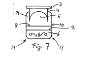
- Fig. 7 shows a view similar to fig. 3, wherein the strips 6 are rouded on both sides at their lower ends 17 and have at two locations a perforation 18 in the lower part below the buckels 8, 9.
- a perforation 18 in the one strip 6 is in line with a perforation 18 in the opposite strip 6. Liquid can flow from the gap 7 between de strips 6 through the perforations 18 or the lower edge of the seal 1 (viewed in flow direction A) to exit the seal 1.
Landscapes
- Engineering & Computer Science (AREA)
- General Engineering & Computer Science (AREA)
- Mechanical Engineering (AREA)
- Environmental & Geological Engineering (AREA)
- Health & Medical Sciences (AREA)
- Life Sciences & Earth Sciences (AREA)
- Hydrology & Water Resources (AREA)
- Public Health (AREA)
- Water Supply & Treatment (AREA)
- Pipe Accessories (AREA)
Applications Claiming Priority (4)
| Application Number | Priority Date | Filing Date | Title |
|---|---|---|---|
| NL1023417 | 2003-05-14 | ||
| NL1023417 | 2003-05-14 | ||
| NL1024305 | 2003-09-16 | ||
| NL1024305 | 2003-09-16 |
Publications (2)
| Publication Number | Publication Date |
|---|---|
| EP1477617A2 true EP1477617A2 (fr) | 2004-11-17 |
| EP1477617A3 EP1477617A3 (fr) | 2005-03-09 |
Family
ID=33032453
Family Applications (1)
| Application Number | Title | Priority Date | Filing Date |
|---|---|---|---|
| EP04076419A Withdrawn EP1477617A3 (fr) | 2003-05-14 | 2004-05-13 | Piège à odeurs et dispositif anti-retour |
Country Status (1)
| Country | Link |
|---|---|
| EP (1) | EP1477617A3 (fr) |
Cited By (6)
| Publication number | Priority date | Publication date | Assignee | Title |
|---|---|---|---|---|
| WO2011120177A1 (fr) * | 2010-03-30 | 2011-10-06 | Enswico Ip Ag | Bonde pour appareil sanitaire |
| WO2011120178A1 (fr) * | 2010-03-30 | 2011-10-06 | Enswico Ip Ag | Clapet à monter dans un appareil sanitaire |
| DE102011078884A1 (de) * | 2011-07-08 | 2013-01-10 | Tece Gmbh | Ablaufventil mit Verschlusselement zum Verschließen eines Überlaufrohrs während der Geruchsabsaugung |
| US8621677B2 (en) | 2009-02-27 | 2014-01-07 | Airbus Operations Gmbh | Odour seal for a vacuum toilet drain system |
| WO2015171071A1 (fr) * | 2014-05-09 | 2015-11-12 | Meier Sanitech Pte Ltd | Ensemble et dispositif de soupape sanitaire |
| US10294650B2 (en) | 2016-01-07 | 2019-05-21 | Falcon Waterfree Technologies, Llc | Mechanical valve for waterless urinal |
Family Cites Families (6)
| Publication number | Priority date | Publication date | Assignee | Title |
|---|---|---|---|---|
| DE362324C (de) * | 1922-10-26 | Ernst Kuhn | Aus einem am Ende flachgedrueckten Schlauche bestehendes Lippenventil fuer Fluessigkeiten und Gase | |
| US3047013A (en) * | 1957-03-22 | 1962-07-31 | William J Baumbach | Diaphragm for water closets |
| US5193585A (en) * | 1991-10-28 | 1993-03-16 | Marathon Oil Company | Duckbill conservation vent valve |
| DE19749779A1 (de) * | 1997-11-11 | 1999-05-27 | Manfred Arnold | Geruchsverschluß für ein Abflußrohr, insbesondere für das Abflußrohr eines Waschbeckens, einer Duschwanne oder dergleichen |
| GB2346198B (en) * | 1999-01-25 | 2002-12-18 | Aco Technologies Plc | Non-return device |
| EP1174549A3 (fr) * | 2000-07-19 | 2005-01-12 | Michel Jacques Senteur | Dispositif anti-retour |
-
2004
- 2004-05-13 EP EP04076419A patent/EP1477617A3/fr not_active Withdrawn
Cited By (11)
| Publication number | Priority date | Publication date | Assignee | Title |
|---|---|---|---|---|
| US8621677B2 (en) | 2009-02-27 | 2014-01-07 | Airbus Operations Gmbh | Odour seal for a vacuum toilet drain system |
| DE102009010862B4 (de) * | 2009-02-27 | 2015-04-30 | Airbus Operations Gmbh | Geruchsverschluss für ein Vakuumtoilettenabflusssystem, Ablaufvorrichtung, Vakuumtoilettensystem sowie Flugzeug mit einem solchen Vakuumtoilettensystem |
| WO2011120177A1 (fr) * | 2010-03-30 | 2011-10-06 | Enswico Ip Ag | Bonde pour appareil sanitaire |
| WO2011120178A1 (fr) * | 2010-03-30 | 2011-10-06 | Enswico Ip Ag | Clapet à monter dans un appareil sanitaire |
| CN102812274A (zh) * | 2010-03-30 | 2012-12-05 | 恩茨维柯埃皮股份公司 | 集成于洁具中的阀 |
| US9097355B2 (en) | 2010-03-30 | 2015-08-04 | Enswico Ip Ag | Valve for integrating into a sanitary appliance |
| DE102011078884A1 (de) * | 2011-07-08 | 2013-01-10 | Tece Gmbh | Ablaufventil mit Verschlusselement zum Verschließen eines Überlaufrohrs während der Geruchsabsaugung |
| DE102011078884B4 (de) | 2011-07-08 | 2022-03-10 | Tece Gmbh | Verschlusselement zum Verschließen eines Überlaufrohrs während der Geruchsabsaugung, Ablaufventil mit diesem Verschlusselement sowie Verwendung dieses Verschlusselements |
| WO2015171071A1 (fr) * | 2014-05-09 | 2015-11-12 | Meier Sanitech Pte Ltd | Ensemble et dispositif de soupape sanitaire |
| JP2017519135A (ja) * | 2014-05-09 | 2017-07-13 | マイアー サニテック ピーティーイー エルティーディーMeier Sanitech Pte Ltd | サニタリーバルブ装置およびサニタリーバルブアセンブリ |
| US10294650B2 (en) | 2016-01-07 | 2019-05-21 | Falcon Waterfree Technologies, Llc | Mechanical valve for waterless urinal |
Also Published As
| Publication number | Publication date |
|---|---|
| EP1477617A3 (fr) | 2005-03-09 |
Similar Documents
| Publication | Publication Date | Title |
|---|---|---|
| EP1174549A2 (fr) | Dispositif anti-retour | |
| US20110290349A1 (en) | Non-Return Valve Adapter For Water Closet | |
| KR20120132024A (ko) | 배수 트랩 | |
| EP1477617A2 (fr) | Piège à odeurs et dispositif anti-retour | |
| JP6752411B2 (ja) | 配管構造 | |
| KR100938733B1 (ko) | 배수트랩 | |
| US20070257218A1 (en) | Backflow-Preventer | |
| JP3155258U (ja) | 逆止弁及び床排水トラップ | |
| JP7412179B2 (ja) | 継手管、弁付き継手管 | |
| JP2012127135A (ja) | トイレの排水構造 | |
| JP6194505B2 (ja) | 自封式弁部材及び継ぎ手部材 | |
| US11408160B2 (en) | Reslient fluid control valve above drainage plane | |
| JP6944745B2 (ja) | 排水トラップ | |
| EP3899330B1 (fr) | Vanne pour un appareil sanitaire | |
| KR200451193Y1 (ko) | 배수트랩 | |
| JP5720014B2 (ja) | 自封式排水トラップ | |
| JP3569842B2 (ja) | 排水トラップ及び排水トラップを用いた浴室構造 | |
| KR102571978B1 (ko) | 변기의 냄새 역류 및 소음 방지 장치 | |
| KR200403172Y1 (ko) | 하수구용 악취 차단장치 | |
| CN212026524U (zh) | 一种侧排地漏 | |
| US20190112800A1 (en) | Resilient fluid control valve with drip edge | |
| JP6040354B2 (ja) | 排水装置 | |
| KR200405376Y1 (ko) | 무게중심을 이용한 덮개형 방취구 | |
| JP2010031547A (ja) | サイフォン排水システム | |
| KR20160054173A (ko) | 배수관 악취 차단구 |
Legal Events
| Date | Code | Title | Description |
|---|---|---|---|
| PUAI | Public reference made under article 153(3) epc to a published international application that has entered the european phase |
Free format text: ORIGINAL CODE: 0009012 |
|
| AK | Designated contracting states |
Kind code of ref document: A2 Designated state(s): AT BE BG CH CY CZ DE DK EE ES FI FR GB GR HU IE IT LI LU MC NL PL PT RO SE SI SK TR |
|
| AX | Request for extension of the european patent |
Extension state: AL HR LT LV MK |
|
| PUAL | Search report despatched |
Free format text: ORIGINAL CODE: 0009013 |
|
| AK | Designated contracting states |
Kind code of ref document: A3 Designated state(s): AT BE BG CH CY CZ DE DK EE ES FI FR GB GR HU IE IT LI LU MC NL PL PT RO SE SI SK TR |
|
| AX | Request for extension of the european patent |
Extension state: AL HR LT LV MK |
|
| AKX | Designation fees paid | ||
| REG | Reference to a national code |
Ref country code: DE Ref legal event code: 8566 |
|
| STAA | Information on the status of an ep patent application or granted ep patent |
Free format text: STATUS: THE APPLICATION IS DEEMED TO BE WITHDRAWN |
|
| 18D | Application deemed to be withdrawn |
Effective date: 20050910 |