EP1477655A1 - Verfahren für eine kontrollierte Beigabe eines Reduktionsmittels in ein stickstoffoxidhaltiges Abgas - Google Patents
Verfahren für eine kontrollierte Beigabe eines Reduktionsmittels in ein stickstoffoxidhaltiges Abgas Download PDFInfo
- Publication number
- EP1477655A1 EP1477655A1 EP04010280A EP04010280A EP1477655A1 EP 1477655 A1 EP1477655 A1 EP 1477655A1 EP 04010280 A EP04010280 A EP 04010280A EP 04010280 A EP04010280 A EP 04010280A EP 1477655 A1 EP1477655 A1 EP 1477655A1
- Authority
- EP
- European Patent Office
- Prior art keywords
- exhaust gas
- reducing agent
- nitrogen oxides
- catalyst
- engine
- Prior art date
- Legal status (The legal status is an assumption and is not a legal conclusion. Google has not performed a legal analysis and makes no representation as to the accuracy of the status listed.)
- Withdrawn
Links
Images
Classifications
-
- F—MECHANICAL ENGINEERING; LIGHTING; HEATING; WEAPONS; BLASTING
- F01—MACHINES OR ENGINES IN GENERAL; ENGINE PLANTS IN GENERAL; STEAM ENGINES
- F01N—GAS-FLOW SILENCERS OR EXHAUST APPARATUS FOR MACHINES OR ENGINES IN GENERAL; GAS-FLOW SILENCERS OR EXHAUST APPARATUS FOR INTERNAL-COMBUSTION ENGINES
- F01N3/00—Exhaust or silencing apparatus having means for purifying, rendering innocuous, or otherwise treating exhaust
- F01N3/08—Exhaust or silencing apparatus having means for purifying, rendering innocuous, or otherwise treating exhaust for rendering innocuous
- F01N3/10—Exhaust or silencing apparatus having means for purifying, rendering innocuous, or otherwise treating exhaust for rendering innocuous by thermal or catalytic conversion of noxious components of exhaust
- F01N3/18—Exhaust or silencing apparatus having means for purifying, rendering innocuous, or otherwise treating exhaust for rendering innocuous by thermal or catalytic conversion of noxious components of exhaust characterised by methods of operation; Control
- F01N3/20—Exhaust or silencing apparatus having means for purifying, rendering innocuous, or otherwise treating exhaust for rendering innocuous by thermal or catalytic conversion of noxious components of exhaust characterised by methods of operation; Control specially adapted for catalytic conversion
- F01N3/206—Adding periodically or continuously substances to exhaust gases for promoting purification, e.g. catalytic material in liquid form, NOx reducing agents
- F01N3/208—Control of selective catalytic reduction [SCR], e.g. by adjusting the dosing of reducing agent
-
- F—MECHANICAL ENGINEERING; LIGHTING; HEATING; WEAPONS; BLASTING
- F01—MACHINES OR ENGINES IN GENERAL; ENGINE PLANTS IN GENERAL; STEAM ENGINES
- F01N—GAS-FLOW SILENCERS OR EXHAUST APPARATUS FOR MACHINES OR ENGINES IN GENERAL; GAS-FLOW SILENCERS OR EXHAUST APPARATUS FOR INTERNAL-COMBUSTION ENGINES
- F01N9/00—Electrical control of exhaust gas treating apparatus
- F01N9/005—Electrical control of exhaust gas treating apparatus using models instead of sensors to determine operating characteristics of exhaust systems, e.g. calculating catalyst temperature instead of measuring it directly
-
- F—MECHANICAL ENGINEERING; LIGHTING; HEATING; WEAPONS; BLASTING
- F02—COMBUSTION ENGINES; HOT-GAS OR COMBUSTION-PRODUCT ENGINE PLANTS
- F02D—CONTROLLING COMBUSTION ENGINES
- F02D41/00—Electrical control of supply of combustible mixture or its constituents
- F02D41/24—Electrical control of supply of combustible mixture or its constituents characterised by the use of digital means
- F02D41/26—Electrical control of supply of combustible mixture or its constituents characterised by the use of digital means using computer, e.g. microprocessor
- F02D41/28—Interface circuits
-
- F—MECHANICAL ENGINEERING; LIGHTING; HEATING; WEAPONS; BLASTING
- F01—MACHINES OR ENGINES IN GENERAL; ENGINE PLANTS IN GENERAL; STEAM ENGINES
- F01N—GAS-FLOW SILENCERS OR EXHAUST APPARATUS FOR MACHINES OR ENGINES IN GENERAL; GAS-FLOW SILENCERS OR EXHAUST APPARATUS FOR INTERNAL-COMBUSTION ENGINES
- F01N2560/00—Exhaust systems with means for detecting or measuring exhaust gas components or characteristics
- F01N2560/02—Exhaust systems with means for detecting or measuring exhaust gas components or characteristics the means being an exhaust gas sensor
- F01N2560/025—Exhaust systems with means for detecting or measuring exhaust gas components or characteristics the means being an exhaust gas sensor for measuring or detecting O2, e.g. lambda sensors
-
- F—MECHANICAL ENGINEERING; LIGHTING; HEATING; WEAPONS; BLASTING
- F01—MACHINES OR ENGINES IN GENERAL; ENGINE PLANTS IN GENERAL; STEAM ENGINES
- F01N—GAS-FLOW SILENCERS OR EXHAUST APPARATUS FOR MACHINES OR ENGINES IN GENERAL; GAS-FLOW SILENCERS OR EXHAUST APPARATUS FOR INTERNAL-COMBUSTION ENGINES
- F01N2560/00—Exhaust systems with means for detecting or measuring exhaust gas components or characteristics
- F01N2560/02—Exhaust systems with means for detecting or measuring exhaust gas components or characteristics the means being an exhaust gas sensor
- F01N2560/026—Exhaust systems with means for detecting or measuring exhaust gas components or characteristics the means being an exhaust gas sensor for measuring or detecting NOx
-
- F—MECHANICAL ENGINEERING; LIGHTING; HEATING; WEAPONS; BLASTING
- F01—MACHINES OR ENGINES IN GENERAL; ENGINE PLANTS IN GENERAL; STEAM ENGINES
- F01N—GAS-FLOW SILENCERS OR EXHAUST APPARATUS FOR MACHINES OR ENGINES IN GENERAL; GAS-FLOW SILENCERS OR EXHAUST APPARATUS FOR INTERNAL-COMBUSTION ENGINES
- F01N2560/00—Exhaust systems with means for detecting or measuring exhaust gas components or characteristics
- F01N2560/06—Exhaust systems with means for detecting or measuring exhaust gas components or characteristics the means being a temperature sensor
-
- F—MECHANICAL ENGINEERING; LIGHTING; HEATING; WEAPONS; BLASTING
- F01—MACHINES OR ENGINES IN GENERAL; ENGINE PLANTS IN GENERAL; STEAM ENGINES
- F01N—GAS-FLOW SILENCERS OR EXHAUST APPARATUS FOR MACHINES OR ENGINES IN GENERAL; GAS-FLOW SILENCERS OR EXHAUST APPARATUS FOR INTERNAL-COMBUSTION ENGINES
- F01N2610/00—Adding substances to exhaust gases
- F01N2610/02—Adding substances to exhaust gases the substance being ammonia or urea
-
- F—MECHANICAL ENGINEERING; LIGHTING; HEATING; WEAPONS; BLASTING
- F01—MACHINES OR ENGINES IN GENERAL; ENGINE PLANTS IN GENERAL; STEAM ENGINES
- F01N—GAS-FLOW SILENCERS OR EXHAUST APPARATUS FOR MACHINES OR ENGINES IN GENERAL; GAS-FLOW SILENCERS OR EXHAUST APPARATUS FOR INTERNAL-COMBUSTION ENGINES
- F01N2610/00—Adding substances to exhaust gases
- F01N2610/14—Arrangements for the supply of substances, e.g. conduits
- F01N2610/1453—Sprayers or atomisers; Arrangement thereof in the exhaust apparatus
- F01N2610/146—Control thereof, e.g. control of injectors or injection valves
-
- F—MECHANICAL ENGINEERING; LIGHTING; HEATING; WEAPONS; BLASTING
- F01—MACHINES OR ENGINES IN GENERAL; ENGINE PLANTS IN GENERAL; STEAM ENGINES
- F01N—GAS-FLOW SILENCERS OR EXHAUST APPARATUS FOR MACHINES OR ENGINES IN GENERAL; GAS-FLOW SILENCERS OR EXHAUST APPARATUS FOR INTERNAL-COMBUSTION ENGINES
- F01N2900/00—Details of electrical control or of the monitoring of the exhaust gas treating apparatus
- F01N2900/06—Parameters used for exhaust control or diagnosing
- F01N2900/08—Parameters used for exhaust control or diagnosing said parameters being related to the engine
-
- F—MECHANICAL ENGINEERING; LIGHTING; HEATING; WEAPONS; BLASTING
- F02—COMBUSTION ENGINES; HOT-GAS OR COMBUSTION-PRODUCT ENGINE PLANTS
- F02D—CONTROLLING COMBUSTION ENGINES
- F02D41/00—Electrical control of supply of combustible mixture or its constituents
- F02D41/24—Electrical control of supply of combustible mixture or its constituents characterised by the use of digital means
- F02D41/26—Electrical control of supply of combustible mixture or its constituents characterised by the use of digital means using computer, e.g. microprocessor
- F02D41/28—Interface circuits
- F02D2041/281—Interface circuits between sensors and control unit
- F02D2041/285—Interface circuits between sensors and control unit the sensor having a signal processing unit external to the engine control unit
-
- Y—GENERAL TAGGING OF NEW TECHNOLOGICAL DEVELOPMENTS; GENERAL TAGGING OF CROSS-SECTIONAL TECHNOLOGIES SPANNING OVER SEVERAL SECTIONS OF THE IPC; TECHNICAL SUBJECTS COVERED BY FORMER USPC CROSS-REFERENCE ART COLLECTIONS [XRACs] AND DIGESTS
- Y02—TECHNOLOGIES OR APPLICATIONS FOR MITIGATION OR ADAPTATION AGAINST CLIMATE CHANGE
- Y02A—TECHNOLOGIES FOR ADAPTATION TO CLIMATE CHANGE
- Y02A50/00—TECHNOLOGIES FOR ADAPTATION TO CLIMATE CHANGE in human health protection, e.g. against extreme weather
- Y02A50/20—Air quality improvement or preservation, e.g. vehicle emission control or emission reduction by using catalytic converters
-
- Y—GENERAL TAGGING OF NEW TECHNOLOGICAL DEVELOPMENTS; GENERAL TAGGING OF CROSS-SECTIONAL TECHNOLOGIES SPANNING OVER SEVERAL SECTIONS OF THE IPC; TECHNICAL SUBJECTS COVERED BY FORMER USPC CROSS-REFERENCE ART COLLECTIONS [XRACs] AND DIGESTS
- Y02—TECHNOLOGIES OR APPLICATIONS FOR MITIGATION OR ADAPTATION AGAINST CLIMATE CHANGE
- Y02T—CLIMATE CHANGE MITIGATION TECHNOLOGIES RELATED TO TRANSPORTATION
- Y02T10/00—Road transport of goods or passengers
- Y02T10/10—Internal combustion engine [ICE] based vehicles
- Y02T10/12—Improving ICE efficiencies
-
- Y—GENERAL TAGGING OF NEW TECHNOLOGICAL DEVELOPMENTS; GENERAL TAGGING OF CROSS-SECTIONAL TECHNOLOGIES SPANNING OVER SEVERAL SECTIONS OF THE IPC; TECHNICAL SUBJECTS COVERED BY FORMER USPC CROSS-REFERENCE ART COLLECTIONS [XRACs] AND DIGESTS
- Y02—TECHNOLOGIES OR APPLICATIONS FOR MITIGATION OR ADAPTATION AGAINST CLIMATE CHANGE
- Y02T—CLIMATE CHANGE MITIGATION TECHNOLOGIES RELATED TO TRANSPORTATION
- Y02T10/00—Road transport of goods or passengers
- Y02T10/10—Internal combustion engine [ICE] based vehicles
- Y02T10/40—Engine management systems
Definitions
- the present invention relates to reduction of content of nitrogen oxides (NOx) by means of selective catalytic reduction with injection of reducing agents onboard vehicles with internal combustion engines.
- NOx nitrogen oxides
- SCR selective catalytic reduction
- ammonia or urea act as a reducing agent.
- the reducing agent reacts with nitrogen oxides from the exhaust to form nitrogen and water.
- Ammonia or urea is added to the exhaust gas from an external source either as in aqueous solution or as urea as a solid or dissolved in water. If urea is used, it will be thermally decomposed to ammonia and isocyanic acid by the heat in the exhaust or hydrolysed over the SCR catalyst to form carbon dioxide and ammonia.
- V 2 O5-WO 3 /TiO 2 catalysts are employed in the SCR process even though other base metal oxides have SCR activity.
- An electronic control unit is usually employed to meter urea or ammonia reducing agent injection, which must correspond to the potential of the catalyst to reduce NOx.
- the reduction capability depends on the activity of the catalyst, the temperature of the exhaust, the massflow of the exhaust and the NOx concentration in the exhaust.
- the oxygen content and the water content of the exhaust affects the reduction capability but are considered to have a minor effect.
- the most important parameters like exhaust mass flow, NOx concentration and catalyst temperature are in the known methods and systems for NOx control in exhaust from diesel fueled engines determined by the means of sensors, arranged in the exhaust gas channel of the engine.
- the measured data are then transmitted to the ECU, where the data are converted to an appropriate output signal by means of an algorithm to a metering pump for the controlled injection of reducing agent into the exhaust gas stream.
- the invention is an improved method for controlled addition of a reducing agent into nitrogen oxides containing vehicle engine exhaust gas by reaction of the nitrogen oxides with a reducing agent in contact with a selective reducing catalyst amount of the reducing agent being added to the exhaust gas is metered on base of exhaust gas values and/or engine values, which values are determined by means of sensors and sensor data being communicated to an electronic control unit for metering the amount of the reducing agent being added to the exhaust gas, the improvement of which comprises communicating the sensor data by means of a serial interface to the electronic control unit.
- the invention provides furthermore an improved system for metering a reducing agent into nitrogen oxides containing exhaust gas for catalytic reduction of the nitrogen oxides, which system is useful for operating the inventive method.
- the essential feature of the method and system according to the invention is transmission of sensor data with a serial interface to the electronic control unit (ECU), whereby electromagnetic disturbances induced by electrical field on the vehicle are avoided.
- the sensors are equipped with the serial interface, which makes it possible to arrange the ECU in a remote position from the sensors.
- an ECU being equipped with a serial interface instead of a circuit for measurements of analogue signals from the sensors allows monitoring of the air flow transmitted by a serial interface mounted directly on or in close connection to air flow sensors, which could be placed in the engine compartment.
- Measured values of the intake airflow to the engine and oxygen content in the exhaust allows calculating the exhaust mass flow. From the oxygen content in the exhaust and the inlet airflow, the fuel consumption is derived. The fuel consumption, as a molar flow, is then added to the engine inlet air molar flow giving the exhaust molar flow. By knowing an average molar weight of the exhaust gas, the exhaust gas massflow can be calculated with accuracy accurate enough for this application.
- Determination of exhaust massflow by calculation as described above is based on data measured by low cost sensors for intake airflow and for oxygen concentration instead of use of expensive exhaust gas flow sensors arranged in the exhaust gas channel as typically applied in prior art.
- the NOx mass flow is calculated by the ECU based on data of the NOx concentration in the exhaust gas upstream the catalyst and the point for urea injection, transmitted from a NOx sensor or other analyser.
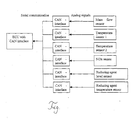
- the NOx sensor is equipped with a serial interface, preferable a Controller Area Network, CAN interface, able to communicate with the electronic control unit via a serial link.
- CANbus was originally developed by Bosch for automotive applications. It is a high speed serial data network engineered to exist in harsh electrical environments. It answers also a lot of the issues of predictability and latency in its basic design - by using non-destructive priority based message arbitration.
- the temperature in the exhaust has to be measured.
- the temperature sensors could be equipped with a serial interface, preferable a CAN interface, able to communicate with the electronic control unit via a serial link as schematically shown in the attached Figure.
Landscapes
- Engineering & Computer Science (AREA)
- Chemical & Material Sciences (AREA)
- General Engineering & Computer Science (AREA)
- Combustion & Propulsion (AREA)
- Mechanical Engineering (AREA)
- Chemical Kinetics & Catalysis (AREA)
- Microelectronics & Electronic Packaging (AREA)
- Computer Hardware Design (AREA)
- Health & Medical Sciences (AREA)
- Toxicology (AREA)
- Analytical Chemistry (AREA)
- Exhaust Gas After Treatment (AREA)
- Combined Controls Of Internal Combustion Engines (AREA)
- Exhaust Gas Treatment By Means Of Catalyst (AREA)
Applications Claiming Priority (2)
| Application Number | Priority Date | Filing Date | Title |
|---|---|---|---|
| DKPA200300723 | 2003-05-13 | ||
| DK200300723 | 2003-05-13 |
Publications (1)
| Publication Number | Publication Date |
|---|---|
| EP1477655A1 true EP1477655A1 (de) | 2004-11-17 |
Family
ID=33016790
Family Applications (1)
| Application Number | Title | Priority Date | Filing Date |
|---|---|---|---|
| EP04010280A Withdrawn EP1477655A1 (de) | 2003-05-13 | 2004-04-30 | Verfahren für eine kontrollierte Beigabe eines Reduktionsmittels in ein stickstoffoxidhaltiges Abgas |
Country Status (6)
| Country | Link |
|---|---|
| US (1) | US20040226286A1 (de) |
| EP (1) | EP1477655A1 (de) |
| JP (1) | JP2004340146A (de) |
| CN (1) | CN1609420A (de) |
| CA (1) | CA2467178A1 (de) |
| RU (1) | RU2004114304A (de) |
Cited By (1)
| Publication number | Priority date | Publication date | Assignee | Title |
|---|---|---|---|---|
| FR2919666A1 (fr) * | 2007-08-03 | 2009-02-06 | Peugeot Citroen Automobiles Sa | Systeme de gestion d'un circuit de distribution d'un reactif dans une ligne d'echappement |
Families Citing this family (6)
| Publication number | Priority date | Publication date | Assignee | Title |
|---|---|---|---|---|
| US20070042495A1 (en) * | 2005-08-22 | 2007-02-22 | Detroit Diesel Corporation | Method of controlling injection of a reducing agent in an engine emissions control system |
| DE102006004170A1 (de) * | 2006-01-27 | 2007-08-02 | Pierburg Gmbh | Vorrichtung zur Reduktion von Stickoxiden im Abgas von Brennkraftmaschinen |
| DE102006061732A1 (de) * | 2006-12-28 | 2008-07-03 | Robert Bosch Gmbh | Vorrichtung zum Dosieren eines flüssigen Reduktionsmittels |
| US8713917B2 (en) * | 2007-08-30 | 2014-05-06 | GM Global Technology Operations LLC | Method for reducing NH3 release from SCR catalysts during thermal transients |
| CN102998355B (zh) * | 2012-12-17 | 2016-01-13 | 潍柴动力股份有限公司 | 一种发动机下线检测氮氧化物排放的方法及系统 |
| SE542332C2 (en) * | 2018-04-24 | 2020-04-14 | Scania Cv Ab | Method and system for control of an activation of at least one liquid sensitive sensor |
Citations (5)
| Publication number | Priority date | Publication date | Assignee | Title |
|---|---|---|---|---|
| DE19807215A1 (de) * | 1998-02-20 | 1999-08-26 | Siemens Ag | Steuersystem für eine Brennkraftmaschine |
| US6415602B1 (en) * | 2000-10-16 | 2002-07-09 | Engelhard Corporation | Control system for mobile NOx SCR applications |
| US20020103592A1 (en) * | 2000-09-29 | 2002-08-01 | Helmut Gross | Method and device for controlling operational sequences |
| US6446600B1 (en) * | 1997-07-03 | 2002-09-10 | Daimler-Benz Aktiengesellschaft | Sensor arrangement and engine management device for a combustion engine |
| US20030033799A1 (en) * | 2001-08-09 | 2003-02-20 | Gerd Scheying | Exhaust gas treatment unit and measuring instrument for ascertaining a concentration of a urea-water solution |
Family Cites Families (13)
| Publication number | Priority date | Publication date | Assignee | Title |
|---|---|---|---|---|
| JPH1047048A (ja) * | 1996-08-02 | 1998-02-17 | Toyota Motor Corp | 内燃機関の排気浄化装置 |
| DE19704558A1 (de) * | 1997-02-06 | 1998-08-13 | Siemens Ag | Verfahren und Einrichtung zur katalytischen Abgasreinigung sowie Verbrennungsanlage |
| DE19736384A1 (de) * | 1997-08-21 | 1999-02-25 | Man Nutzfahrzeuge Ag | Verfahren zur Dosierung eines Reduktionsmittels in stickoxidhaltiges Abgas einer Brennkraftmaschine |
| DE19740702C1 (de) * | 1997-09-16 | 1998-11-19 | Siemens Ag | Verfahren und Vorrichtung zum Betrieb einer mit Luftüberschuß arbeitenden Brennkraftmaschine |
| DE19743337C1 (de) * | 1997-09-30 | 1999-01-07 | Siemens Ag | NOx-Reduktionssystem mit einer Einrichtung zur Reduktionsmitteldosierung |
| DE19749400C2 (de) * | 1997-11-07 | 2001-11-29 | Siemens Ag | Verfahren zur Verringerung des NOX-Gehaltes im Abgas einer Dieselbrennkraftmaschine |
| DE19814386C2 (de) * | 1998-03-31 | 2000-06-08 | Siemens Ag | Verfahren und Vorrichtung zur katalytischen Entfernung von Stickoxiden im Abgas einer Verbrennungsanlage |
| DE19819579C1 (de) * | 1998-04-30 | 1999-09-30 | Siemens Ag | Verfahren und Vorrichtung zur Abgasnachbehandlung für eine mit einem SCR-Katalysator ausgestattete Brennkraftmaschine |
| US6357226B2 (en) * | 1998-10-22 | 2002-03-19 | Chrysler Corporation | Control system for lean air-fuel ratio NOx catalyst system |
| US6427439B1 (en) * | 2000-07-13 | 2002-08-06 | Ford Global Technologies, Inc. | Method and system for NOx reduction |
| US6725651B2 (en) * | 2000-11-16 | 2004-04-27 | Toyota Jidosha Kabushiki Kaisha | Reducing agent for emission control system, reducing-agent supply device, and emission control system using the reducing agent |
| EP1454203A2 (de) * | 2002-02-05 | 2004-09-08 | Cleaire Advanced Emission Controls | Verfahren und vorrichtung zur gleichzeitigen überwachung,registrierung und steuerung einer industriellen anlage |
| JP3951774B2 (ja) * | 2002-03-29 | 2007-08-01 | 三菱ふそうトラック・バス株式会社 | 内燃機関のNОx浄化装置 |
-
2004
- 2004-04-30 EP EP04010280A patent/EP1477655A1/de not_active Withdrawn
- 2004-05-05 US US10/838,367 patent/US20040226286A1/en not_active Abandoned
- 2004-05-12 RU RU2004114304/06A patent/RU2004114304A/ru not_active Application Discontinuation
- 2004-05-12 CA CA002467178A patent/CA2467178A1/en not_active Abandoned
- 2004-05-12 JP JP2004142337A patent/JP2004340146A/ja not_active Withdrawn
- 2004-05-13 CN CNA2004100477892A patent/CN1609420A/zh active Pending
Patent Citations (5)
| Publication number | Priority date | Publication date | Assignee | Title |
|---|---|---|---|---|
| US6446600B1 (en) * | 1997-07-03 | 2002-09-10 | Daimler-Benz Aktiengesellschaft | Sensor arrangement and engine management device for a combustion engine |
| DE19807215A1 (de) * | 1998-02-20 | 1999-08-26 | Siemens Ag | Steuersystem für eine Brennkraftmaschine |
| US20020103592A1 (en) * | 2000-09-29 | 2002-08-01 | Helmut Gross | Method and device for controlling operational sequences |
| US6415602B1 (en) * | 2000-10-16 | 2002-07-09 | Engelhard Corporation | Control system for mobile NOx SCR applications |
| US20030033799A1 (en) * | 2001-08-09 | 2003-02-20 | Gerd Scheying | Exhaust gas treatment unit and measuring instrument for ascertaining a concentration of a urea-water solution |
Non-Patent Citations (1)
| Title |
|---|
| HEINTZ F ET AL: "EINSATZMOEGLICHKEITEN UND ZUKUNFTSCHANCEN INTELLIGENTER SENSOREN IM KRAFTFAHRZEUG", BOSCH TECHNISCHE BERICHTE, ROBERT BOSCH, STUTTGART, DE, no. 52, 1 October 1990 (1990-10-01), pages 30 - 41, XP000177040, ISSN: 0006-789X * |
Cited By (2)
| Publication number | Priority date | Publication date | Assignee | Title |
|---|---|---|---|---|
| FR2919666A1 (fr) * | 2007-08-03 | 2009-02-06 | Peugeot Citroen Automobiles Sa | Systeme de gestion d'un circuit de distribution d'un reactif dans une ligne d'echappement |
| WO2009024701A1 (fr) * | 2007-08-03 | 2009-02-26 | Peugeot Citroën Automobiles SA | Systeme de gestion d'un circuit de distribution d'un reactif dans une ligne d'echappement |
Also Published As
| Publication number | Publication date |
|---|---|
| CN1609420A (zh) | 2005-04-27 |
| RU2004114304A (ru) | 2005-10-27 |
| US20040226286A1 (en) | 2004-11-18 |
| JP2004340146A (ja) | 2004-12-02 |
| CA2467178A1 (en) | 2004-11-13 |
Similar Documents
| Publication | Publication Date | Title |
|---|---|---|
| US6082102A (en) | NOx reduction system with a device for metering reducing agents | |
| US9657630B2 (en) | Diagnostic systems and methods for selective catalytic reduction (SCR) systems based on NOx sensor feedback | |
| EP1830040B1 (de) | Motorabgasreinigungsvorrichtung | |
| US8694197B2 (en) | Gain/amplitude diagnostics of NOx sensors | |
| JP4682035B2 (ja) | 燃焼機関からの排ガス中の還元剤の注入を制御する方法 | |
| KR101416408B1 (ko) | 요소 품질 센서의 고장 진단 방법 및 장치 | |
| US20040098968A1 (en) | Exhaust gas aftertreatment systems | |
| US9097159B2 (en) | Method for detecting urea deposits in an exhaust line of an automotive vehicle, method for eliminating urea deposits and automotive vehicle adapted to such methods | |
| US10634032B2 (en) | Method and apparatus for monitoring an exhaust aftertreatment system for an internal combustion engine | |
| EP0939206A3 (de) | Vorrichtung zur Reduzierung des NOx-Gehaltes im Abgas einer Brennkraftmaschine | |
| JP2004176719A (ja) | 排気ガス後処理システムを監視するための方法および装置 | |
| US20120000185A1 (en) | Method for detecting abnormality in reducing agent | |
| US8549836B2 (en) | Method for operating an exhaust system, exhaust system and vehicle having an exhaust system | |
| US8682595B2 (en) | Method to estimate NO2 concentration in an exhaust gas of an internal combustion engine | |
| EP2284369B1 (de) | Einrichtung zur überprüfung einer vorrichtung zur zuführung von reduktionsmittel | |
| US20040226286A1 (en) | Process for controlled addition of a reducing agent into nitrogen oxides containing exhaust gas | |
| EP3943729A1 (de) | Verfahren zur diagnose und zum betrieb eines abgasnachbehandlungssystems | |
| US9249705B2 (en) | Metering unit for a reducing agent, method for metering reducing agent and motor vehicle having a metering unit | |
| US20190376426A1 (en) | Control apparatus and method with nox sensor cross sensitivity for operating an internal combustion engine | |
| GB2403165A (en) | Correlating reductant injection with NOx leve | |
| US20180334943A1 (en) | Urea Deposit Detection For Use With SCR Emissions Control System | |
| KR100398099B1 (ko) | 온도 rpm제어형 Urea-SCR 시스템 | |
| US12392269B2 (en) | Control device and method for deriving engine-out NOx concentration | |
| JP2009102995A (ja) | 排気ガス浄化システムの故障診断装置 | |
| CN115822766A (zh) | Scr转化效率测试方法、装置、电子设备及存储介质 |
Legal Events
| Date | Code | Title | Description |
|---|---|---|---|
| PUAI | Public reference made under article 153(3) epc to a published international application that has entered the european phase |
Free format text: ORIGINAL CODE: 0009012 |
|
| AK | Designated contracting states |
Kind code of ref document: A1 Designated state(s): AT BE BG CH CY CZ DE DK EE ES FI FR GB GR HU IE IT LI LU MC NL PL PT RO SE SI SK TR |
|
| AX | Request for extension of the european patent |
Extension state: AL HR LT LV MK |
|
| 17P | Request for examination filed |
Effective date: 20050517 |
|
| AKX | Designation fees paid |
Designated state(s): AT BE BG CH CY CZ DE DK EE ES FI FR GB GR HU IE IT LI LU MC NL PL PT RO SE SI SK TR |
|
| 17Q | First examination report despatched |
Effective date: 20051003 |
|
| STAA | Information on the status of an ep patent application or granted ep patent |
Free format text: STATUS: THE APPLICATION IS DEEMED TO BE WITHDRAWN |
|
| 18D | Application deemed to be withdrawn |
Effective date: 20061229 |